1
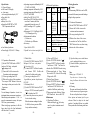
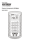
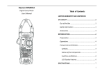
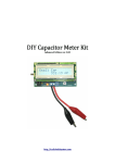
SMD METER
USER’S MANUAL
MODEL: 990C
Table of Contents
1. Introduction
1.Introduction
2.Safety note
3.Explanation of Controls and Indicators
3-1.Product Illustration
3-2.Push Buttons
3-3.LCD display
4.Specification
4-1.General Feature
4-2.Electrical Specification
5.Testing Operation
5-1.Resistance Measurement
5-2.Capacitance Measurement
5-3.Diode Check
5-4.Continuity Check
5-5. Zener/LED Measurement
5-6. Battery Power Measurement
6.Maintenance
6-1.Replacing The Battery
6-2.Cleaning
The Meter is a handheld and battery operated very
convenient small Tool, that is specially used to
measuring SMD(Surface Mounting Device),there
are resistor, Capacitor, Diode, Zener and LED,
Moreover, the Meter have the continuity checking
function And batery power Measurement.
The Meter is designed to meet IEC1010-1 standard
and Stipulation of 2-Pollution Grade.
The Meter conform to the European Union‟s
following Requirement:CE regulation 89/336
(EMC Electromagnetic Compatibility).
The entire outer surface of the Meter case has been
with thermo plastic elastomer, and the two testing
pins has been gold-plated, so that it is reduce pin
contact resistance and prevent to get rusty.
This operating instruction covers information on
safety and caution,so please read relevant
information carefully and observe all the warming
and note strictly.
-23. Explanation of Control and Indicators
3.1 Product Illustration
6
5
4
2
1
3
7
①
②
③
④
⑤
⑥
⑦
⑧
8
LCD
"REL"Push Button
"FUNC" Push Button Function Select
FUNCTION Switch
Pin Holder
Test Pin (Gold plated, 'INPUT' Terminal)
Test Pin (Gold plated, 'COM' Terminal)
Battery cover
-5-
3.2.Push Buttons
[1]"FUNC":it is the function select key that
acts trigger.
Use the Push Button as switch of
Resistance/Capacitance/Diode/Continuity
when the FUNCTION Switch turn on
“R/D/C” Range.
The Meter is have not Power Key. When
install the 1.5V(AAA)×2 Battery,The
Meter immediately Power ON.
[2]"REL" Key: Press "REL" Button to
Enter or exit the relative value measu
-ring mode .
Push the key, the present display value will be
stored in memory, then the new display
value is the difference between input value
and stored data.
-6–
2.Safety Note
The following safety notes should be observed
prior to using this Meter and any associated
accessory.Although the Meter do not used to
measuring to exceed Safety Voltage ,but
there are situations where hazardous conditi
-on may be present.
● Inspect the Meter case before using.Do
Not use damaged device.
● Inspect the Pin Holder and Pin gold
-plated state.
● Do not attempt use the Meter as tweezers
to prevent the pin tip from damage.
● Do not used in the environment with
explosive gas,vapor,or dust.
Caution
Never use the Meter on alive circuits .
-3Note: after auto power-OFF is active,
pushing the "REL" key can turn on the Meter
again .
-4NO
Indicato
Meaning
1
AUTO
Auto Ranging
2
DC
Direct current
3
REL
Relative Testing
4
5
3-3.LCD Display
6
nuF
7
MKΩ
8
V
9
-7-
Diode
Checking Mode
Continuity
Checking Mode
Capacitance
Units(nF,uF)
Resistance
Units(Ω, KΩ,MΩ)
Voltage Units
Low
Battery lndicator
-8-
4.Specification
4-1.General Feature
● 6000 count LCD display.
● Auto ranges.
● Over-rang indication display “OL”
●Zener diode Test
●LED Test
●Battery Power Test
●Specialized SMD TEST or TEST
DIP Component with leade.
● Low Batteery Indication
● Power Supply: 1.5V(AAA)×2 Battery
● Operating temperature &Humidity:0-40'C
(32-104'F) &<80%RH
● Storage temperature & Humidity:-10-50
● perating temperature &Humidity:0-40℃
(32-104℉) &<80%RH
● Safety Class:IEC1010-1,CAT II
● Auto Power OFF:lf the Meter is idle for
more than 15 minutes,the Meter
automatically tums the power off.
● EMC:According to CE regulation
89/336.
● Dimension(L×W×H) & Weight: 206 X
36 X 25mm,Approx.50 g
● Environmental condition:
(1) Indoor use;
(2) Altitude up to 2000meter.
● Accessory:
1. Spare Test Pin: 2PCS
2. Special Test Leads: electric rating 500V 10A
- 10 -
4-2.Electrical Specification
5-3 Diode Check
[1] Set the FUNCTION Switch to “R/D/C”,
And press „FUNC‟ button until symbol of
“ ” is displayed on LCD.
[2] Connect 'INPUT' Test Pin to the anode,
and Connect 'COM' Test Pin to the
cathode of the diode under testing.
[3] You can get reading from LCD.
A good silicon junction drop between
0.5V-0.8V.
5-4.Continuity Check
[1] Set the FUNCTION Switch at “R/D/C”,
And press „FUNC‟ button until symbol of
“ ” is displayed on LCD.
[2] Connect test pins across two points of
the circuit under testing.
When the resistance reading is less than
10~60 Ω, the buzzer generates 2KHz
beep to indicate continuity.
5-5. Zener or LED Check
[1] Set the FUNCTION Switch to “
”
[2] Connect 'INPUT' Test Pin to the anode,
and Connect 'COM' Test Pin to the
cathode of the ZENER/LED under testing.
[3]The measured value of Zener Voltage
show on the LCD, Or show LED working
Voltage on the LCD.
5-7 Battery Power Measure
[1] Set the FUNCTION Switch to “
”
[2] Connect 'INPUT' Test Pin to the anode,
and Connect 'COM' Test Pin to the
cathode of the Battery under testing.
[3]The measured value of Battery Voltage
at DC10mA load show on the LCD,.
6.Maintenance
6-1.Replacing The Battery
When meter display
,the battery
must be replace to maintain nomal
operaion.
Function.
Range
Resolu
Accuracy
-tion
Resistance 600Ω/6KΩ 0.1Ω ±(1.5%rdg+5dgt)
/60K/600K/
“
6MΩ
“
60MΩ
±(2.5rd%+5dgt)
Capacitance 9.999nF/99.9 1pF ±(2.5%rdg+5dgt)
9nF/999.9nF/
“
9.999μF/99.9
±(3%rdg+5dgt)
9μF/999.9μF
/9.999mF/99.
±(4%rdg+10dgt)
99mF
Diode Test Open Voltage:3.0V, Testing Current : 1.5mA
Continuity When the resistance is less than
Check approx.50Ω,The Buzzer is sounded.
Zener/LED Open Voltage : MIN 20V,
Testing Current : Appr. 1mA
BATTERY Loading Current:
±(1.5rd%+5dgt)
POWER Approx. 10mA
–11 –
5.Testing Operation
Caution
when measuring SMD device on the PCB,
you must be Disconnect power and discharge
all high-voltage capacitors.
5-1. Resistance Measurement
[1] Set the FUNCTION Switch to “R/D/C”
[2] Connect the Test Pins to across the
resistance under measurement.
[3] You can get reading from LCD.
[4] When test low value of the resistance,
You can short two Test Pins, And Press
"REL" Button to clear zero, then testing
to obtain volue of the resisitance.
- 12 -
-95-2.Capacitance Measurement
[1] Set the FUNCTION Switch at “R/D/C”,
And press ‘FUNC’ button until symbol of
“ ” is displayed on LCD.
[2] Connect the Test Pins to across the
Capacitance under measurement.
[3] You can get reading from LCD.
[4] When test low value of the capacitance,
You can press "REL" Button to clear zero,
then testing to obtain precist volue of the
Capacitance.
Caution
To avoid damage to Capacitors should be
discharged before measurement capacitance.
When testing small capacitance(≤1uF), to
assur the measurement accuracy, first press
"REL", then go on measureing.
When testing large capacitance, it will take
longer time before the final indication(it
will take about 4~7 seconds).
- 13 -
- 14 -
- 15 -
[1] Open the battery cover on the bottom
case by pushing the battery cover.
[2] Remove old battery and put new two
into battery holder.
Note:
Battery type: 1.5V(AAA)×2
If you do not use the meter a long
time, pleseRemove the batteries from
the meter.
6-2.Cleaning
The meter can be cleaned with soft clean
cloth to remove any oil,grease or grim.
Do not use liquid solvent or detergent.
Above picture and content just for your
reference. Please be subject to the actual
products if anything different or updated.
Please pardon for not informing in advance.
- 16 -