1
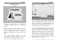
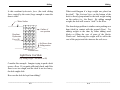
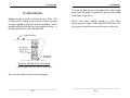
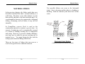
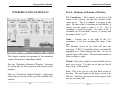
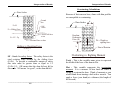
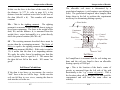
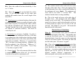
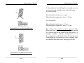
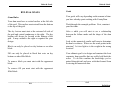
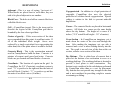
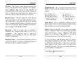
CountyDam A Program for Exploring Introductory Concepts in Engineering Pre-Engineering Software Corporation _ Legal Information Copyright 1994-2005, Pre-Engineering Software Corporation. All rights reserved. License Agreement Pre-Engineering Software Corporation presents CountyDam A Program For Exploring Introductory Concepts in Engineering Written by: Robert A. Wolf III, P.E. Edited by: Mary Anne Wolf, P.E. Cover design by : graphics, etc..., & Bret Guidry System Minimum Requirements: Windows 3.1, 16 color VGA, Microsoft Compatible Mouse This software is licensed to the user for use on one computer. In the case of a multiple license purchase, refer to the license certificate for the number of computers upon which the program may be installed. This software may not be duplicated or transmitted in any form by parties who have not received written authorization from the owner (PreEngineering Software Corporation). This software is licensed "as-is". The owner does not warrant this software or its user's manual to be totally error free. The owner does warrant that the software will perform substantially in accordance with the user's manual and that the disk media is free from any material defect that would impair the performance of the software for a period of 90 days after the purchase date. This software is not intended for professional use. Do not design or construct any structure based on information obtained from the use of this software. The purchaser agrees to defend, save and hold harmless the owner of this software and its employees, officers and re-sellers against any suit or claim (actual or alleged) arising out of the use, miss-use, or inability to use this software. The owner, its employees, officers and resellers shall not be liable for any incidental or consequential damages, or any damages in excess of the original purchase price. Some states do not allow the exclusion or limitation of implied warranty, therefore portions of the above may not apply to you. __________________________________________________ ii Table of Contents Legal Information TABLE OF CONTENTS Acknowledgment of Trademarks CountyDam is a registered trademark of Pre-Engineering Software Corporation. Subject Chapter Trademarks found in the CountyDam program and documentation are the property of their respective holders. The following is a partial list of mentioned trademarks and their holders: Installation & Setup Quick Start 1 2 Overview 3 Microsoft and Windows are registered trademarks of Microsoft Corporation. Sliding Overturning Soil Stress Material Stress 4 5 6 7 __________________________________________________ iii Menu Options Interpretation of Results Rules & Goals 8 9 10 Definitions Technical Support 11 12 __________________________________________________ iv Installation & Setup Installation & Setup Part I - Installing the Software Installing to a Windows 3.1 System Verify that there is at least 4 megs of free space available on your hard drive. It’s a good idea to reserve an additional 10% to 20% of your drive’s capacity for general work space. 1.) Insert the CountyDam CD into CDROM drive. Installing to a Windows95, 98 Me, 2000 or XP System 1.) Insert the CountyDam CD into CDROM drive. 2.) If the CD fails to “autorun”, click the “Start” button, select “Run”, type “D:\install” (Where “D” is the drive letter of your CD ROM drive.) on the “Open” line and click “OK”. 3.) Follow the screen prompts until the install process is complete. 2.) From Window’s “Program Manager” “Run...” from the “File” menu. select 3.) Type “D:\install” (Where “D” is the drive letter of your CD ROM drive.) on the “Command Line” and click “OK”. Follow the screen prompts until the install process is complete. This completes the installation. Store the CountyDam CD in a safe place. Follow the instructions on the CountyDam startup splash screen for entering the program password for the first time. Refer to the cover letter for errata, last minute changes and helpful hints. This completes the installation. Store the CountyDam CD in a safe place. Follow the instructions on the CountyDam startup splash screen for entering the program password for the first time. Refer to the cover letter for errata, last minute changes and helpful hints. __________________________________________________ 1-1 __________________________________________________ 1-2 Installation & Setup Installation & Setup Configuring the Software for Sound The install routine in this chapter automatically configures CountyDam to run in the silent (classroom)mode. To change the program’s “Command Line” so that CountyDam starts in the MCI sound mode, follow these instructions: Software Removal Refer to the Windows’ user’s manual for instructions about deleting files and directories. Highlight the CountyDam icon on the desktop. Right click the mouse. Select “Properties...” from the popup menu. Change the “Command Line” to read “C:\CDWIN\CD M” (include a space before the “M” and do not type the quotes). Click on “OK”. If you do not have a sound card, choose one of the following options: “C:\CDWIN\CD S” for sound with the Windows’ speaker driver. “C:\CDWIN\CD B” for machine beep sounds with no sound driver. “C:\CDWIN\CD A” to have the program ask for sound type with a prompt at startup. “C:\CDWIN\CD” is for silent classroom mode. This mode will remain in effect until it is changed again. __________________________________________________ 1-3 __________________________________________________ 1-4 Quick Start Quick Start QUICK START The purpose of this chapter is to introduce the CountyDam commands necessary for running the program. Note: CountyDam is initially configured to start up in the silent (classroom) mode. Refer to the section entitled “Configuring the Software for Sound” in chapter one for instructions on how to use the sound features. From within “Program Manager” open the “Pre-Engineering Software” group file. Start the program by double clicking the CountyDam icon. __________________________________________________ 2-1 After the introduction screen, the above window will appear. The absence of calculations showing at the top of the window indicates that CountyDam is in the “Design Mode”. Let’s start building a dam. First, tell CountyDam how far the base of the dam will extend to the right. This is done by the placement of dry bottom at the base of the dam. To place a segment of dry bottom, select “Place” from the “Dry Bottom” menu. Locate the cursor arrow at the left and just above the bottom of the grid (coordinate X=1,Y=1) and click the left mouse button. Continue placing segments of dry bottom along the bottom of the grid moving toward the right. __________________________________________________ 2-2 Quick Start For this example, stop the dry bottom at X=8. One unit in the X direction represents a half block (8 inches). Next, start placing the concrete block to construct the structure of the dam. Pull down the “Block” menu and select “Lay” block. Locate the cursor arrow at the left bottom corner of the grid (X=1,Y=1) and click the left mouse button. Quick Start To start the second course, move the cursor to the extreme left end of the second level (X=1,Y=2). This time, instead of clicking the left mouse button, click the right button. When laying block, the right mouse button places a half block under the cursor. If you make a mistake, select “Chip” under the “Block” menu and point & click to erase any misplaced blocks or half blocks. Notice that when a whole block is placed it starts at the cell under the cursor and extends to the cell at the adjacent right. Continue to place whole blocks in this manner until the bottom course is completed. Next, place a whole block starting at X=2,Y=2. Place two more whole blocks, then one half block to complete course number two. Repeat this process until the blocks are stacked to the top of the grid. __________________________________________________ 2-3 __________________________________________________ 2-4 Quick Start Notice that we did not just place whole blocks directly on top of one another (in a stack bond). Instead we used half blocks at the start of alternate courses and created a pattern called a running bond. A running bond is a stronger arrangement. Experiment with both. Quick Start To analyze the dam, pull down the “Analyze” menu and select “Animate Results”. This option will provide numerical results and an animation of those results. Pull down the “File” menu and select the “Save as...” option. In the dialog box provided, type “EX1” for the name of the dam. Do not type an extension. The program will automatically append “.CDD” (CountyDam Data) at the end of the file name. Click on “OK”. The simulation begins with a weather change. Heavy rain in the hills causes the creek beds to fill. Eventually all the water ends up in the river where the dam has been constructed. The water behind the dam rises to the design level. Now the force on the dam exerted by the water is at a maximum. The dam holds for a minute. The man in the truck, sensing danger, speeds away just in the nick of time. The dam fails. Why? __________________________________________________ 2-5 __________________________________________________ 2-6 Let’s save our work. Quick Start The dam slid away. There was not sufficient frictional force at the bottom of the dam to keep it from sliding downstream. What can be done to stop the dam from sliding? Add weight? Notice that this dam failure was animated in the first mode considered, that is, sliding. CountyDam considers sliding first, then overturning, soil stress and material stress. All numerical results are displayed for comparison. Quick Start When finished viewing the numerical results, move the cursor to the grid area and click the left mouse button. This will erase the calculations and place CountyDam in the “design mode” once again. A good way to add weight to the dam is to fill the hollow core of the concrete block. Select “Fill Block” from the “Block Core” menu. To scroll through the results associated with material stress, click over those results. Refer to the section entitled “Interpretation of Results” for a more detailed explanation. __________________________________________________ 2-7 __________________________________________________ 2-8 Quick Start Locate the cursor at the lower left most block and click the left mouse button. Always start with the lowest block and work up. Only block that is resting on dry bottom or other filled blocks can be filled. You may fill as many or as few of the blocks as you wish. For this example, continue filling the block cores until all of the blocks in the dam have been filled. Save the dam under a different name. Select “Save As...” from the “File” menu. Save the dam as “EX2”. Let’s analyze this one. __________________________________________________ 2-9 Quick Start Select “Animate Results” from the “Analyze” menu once again. This time what happened? The heavier dam developed a strong enough frictional force at its base to keep it from sliding. This time it overturned! Continue experimenting until the dam does not fail due to sliding, overturning, soil stress or material stress. This completes the “Quick Start” chapter. For a more detailed look at failure modes, analysis results and possible strategies, continue reading the next chapter, “Overview”. __________________________________________________ 2-10 Overview Overview OVERVIEW The purpose of a dam is to hold back water. There are many reasons for wanting to do this, some of which are: to provide a reservoir to store drinking water; create a lake for recreation; or regulate water flow for hydroelectric power. In order to contain the water, the dam must provide a greater resisting or stabilizing force than the water exerts on it in an attempt to fail it. Top View of Dam A River Bed 200 ft. Top View of Dam In CountyDam, the challenge is: To design and build an 11’- 4” (11.33’) high gravity dam out of concrete block across a 200 foot wide river bed to contain the water that comes down from the neighboring hills. The dam must have a straight vertical wall at the water containment surface. The reservoir created behind the dam will provide drinking water and recreation for a small town. The budget for the project is $100,000.00 ($500 per foot). The dam must be designed to overcome the hydrostatic force that will be trying to fail the dam in one of more of the following modes: * Sliding * Overturning * Soil Stress * Material Stress __________________________________________________ 3-1 Water Level 8"x8"x16" concrete block - typical Vertical Containment Wall 11.33' River Bed Cross-section "A" You will be working with a typical cross-section of the dam as shown in the diagram above. __________________________________________________ 3-2 Sliding Sliding SLIDING The push that the dam feels from the water is called pressure. The magnitude of the pressure that the water exerts along the containment surface of the dam depends on the depth of the water. In other words, just above the surface of the water the dam feels no pressure at all and at the bottom of the containment surface the dam feels the greatest pressure. To calculate the maximum pressure that the water exerts along the bottom edge of the containment surface, multiply the weight of water times the depth. For convenience, the pressure diagram can be replaced by a single resultant force “R” (as shown below) acting perpendicular to and directed toward the containment surface of the dam. Water Surface Resultant Force (R) = average pressure x area = (0+707/2) x (11.33)(1) = 4005 lbs. (or 4.01 kips) 11.33 ft. R = 4.01 kips Water Surface 11.33/3=3.77 ft. Pressure at water surface = weight of water x depth = 62.4 lbs/cu.ft. x 0 ft. = 0 lbs./sq.ft. (psf) Resultant Force 11.33 ft. Containment Surface Pressure at bottom edge = weight of water x depth = 62.4 lbs./cu.ft. x 11.33 ft = 707 psf Pressure Diagram __________________________________________________ 4-1 When working with long structures it is convenient to work with a one foot thick slice of the structure (instead of the entire length). This is where the “1” comes from in the area term of the calculation above. The area that the pressure diagram acts on is 11.33’ x 1’ (or 11.33 sq. ft.). Also, since the pressure varies with depth, the resultant force is not located at the center of the containment surface. It is located at the center of pressure, which is one third of the depth from the bottom. __________________________________________________ 4-2 Sliding Is this resultant hydrostatic force (the total sliding force exerted by the water) large enough to cause the dam to slide? Water Surface Outline of new position Resultant Hydrostatic Force (R) Sliding What would happen if a large weight was placed on the desk? The frictional force on the bottom of the desk is directly proportional to the total weight acting on the surface (i.e., the floor). By adding enough weight, the desk will seem to “stick” to the floor. The dam design problem is similar-water pushing on a dam (desk) in contact with the ground (floor). Try adding weight to the dam by either adding more blocks or filling the core of some of the blocks. Watch out! Increasing the weight will be add to the cost of the project and also increase the soil stress. Soil heave from sliding motion Friction force Light Dams Can Slide (Try adding weight - add block or fill) Consider this example. Imagine trying to push a desk across a floor. If you push sufficiently hard, and if the floor is not too rough, and the desk is not too heavy, the desk might slide. How can the desk be kept from sliding? __________________________________________________ 4-3 __________________________________________________ 4-4 Overturning Overturning OVERTURNING To keep the dam from overturning either add weight away from the point of rotation or increase the width of the base of the dam. Imagine trying to push a tall crate across a floor. The frictional force acting at the bottom of the crate may be large enough to keep the crate from sliding. But, if pushed sufficiently hard, the crate might overturn. A similar problem can exist with the dam. Watch out when adding weight to your dam. Increasing the weight of the dam will add to the cost of the project and also increase the stress on the soil. Water Surface Resultant Hydrostatic Force (R) Center of Rotation Narrow Dams Can Overturn (Add weight to the left side or widen base How can the dam be kept from overturning? __________________________________________________ 5-1 __________________________________________________ 5-2 Soil Stress Soil Stress SOIL STRESS This chapter considers the stress in the soil as a result of the pressure exerted by the dam. The dam must be heavy enough to keep it from either sliding or overturning. If the dam is too heavy though, it could sink into the soil just due to its own weight. If your dam is too heavy, consider increasing the size of the base of the dam. Building columns are sometimes flared for this purpose. Force (F) Water Surface F The force is spread over a larger area, thus reducing the pressure in the soil. Small base Adding size to the base of the dam will also help with another effect that causes an increase in soil stress. The horizontal force of the water causes a tipping toward the toe of the dam. This causes additional compressive stress on the soil in this region. Adding length to the base of the dam is a good way to reduce the soil stress caused by tipping. Large (flared) base Resultant Hydrostatic Force (R) Toe Tipping Causes Additional Soil Stress (Add width to the base) Flared Building Columns __________________________________________________ 6-1 __________________________________________________ 6-2 Material Stress MATERIAL STRESS In the previous chapters, the failure modes that were described considered the dam’s external stability as a solid body. But there is one other distinct way the dam can fail, and that is, the dam can break apart. So, even though the dam may be constructed to withstand sliding, overturning, and soil failure, it may still fail internally. In CountyDam, concrete block is used as the construction material to construct a gravity dam. An amount of reinforcing steel is automatically assumed as a means of limiting cracking due to temperature and curing. However, to present a further challenge, steel may not be added to prevent cracking due to material stress. You must design for this with the strategic placement and filling of the block. Material Stress Two possible failures can occur at the horizontal joints. One is shearing and the other is a bending or breaking. Both are caused by the direct force of the water. Stem Hydrostatic Force (R) R Shear Bending Horizontal Joint Failures There are four types of failures that can occur as a result of too great a stress within the material. (Add block and/or fill block at joint) __________________________________________________ 7-1 __________________________________________________ 7-2 Menu Options Menu Options Save As... MENU OPTIONS File Use this option the first time you save a newly constructed dam or when you want to change the name of the current dam. New Quit - CountyDam Use this option to erase the current dam and start a new one. If the current dam has been changed, you will be given a chance to save it. This option quits CountyDam and returns control to Windows. It you have a current dam that has changes and has not been saved, you will be given the chance to save your work. Open... This option performs the same function as the "New" option listed above. In addition, this option brings up a dialog box for selecting an existing dam from the library. Save Use this option to save a dam that has previously been saved with the "Save As..." option. If this option is selected before using “Save As...”, it will default to “Save As...”. If a dam already exists with this name, a replace option will be given. __________________________________________________ 8-1 Dry Bottom Place Dry Bottom This is the first step to constructing the dam. Dry bottom is a thin layer of concrete that is placed at the bottom of an excavation to serve as a working platform. In CountyDam the placement of dry bottom tells the computer where the base of the dam is located. The dry bottom must start at the extreme left of the grid but can extend to the right anywhere between the left and right limits of the grid. The dry bottom must be continuous. __________________________________________________ 8-2 Menu Options Menu Options When the program is first started, this option will automatically be selected. To place a segment of dry bottom, move the cursor to the location X=1,Y=1 and click the left mouse button. The dry bottom is always placed just below the bottom of the grid. Try this. Place a segment of dry bottom at the left side of the grid. Now place a segment where you want the dry bottom to end. CountyDam will fill in the gap! Remove Dry Bottom Block Lay After placing the dry bottom, select this option to start placing the block to construct your dam. Block can only be placed directly above dry bottom or directly above another block. Click the left mouse button to place a whole block or the right mouse button to place a half block. A half block is placed in the grid cell under the cursor arrow. A whole block is placed such that the left half of the block is placed under the cursor arrow. If you make a mistake placing the dry bottom or later decide to change the size of the base of the dam, use this option to erase that portion of the dry bottom that you wish to change. To remove a segment of the dry bottom, move the cursor to a location just above where you want to erase it (you must erase the dry bottom starting with the right end) and click the left mouse button. Chip __________________________________________________ 8-3 __________________________________________________ 8-4 Select this option to remove whole or half block when editing the dam. The block directly under the cursor will be erased when you click the right or left mouse button. Menu Options Menu Options Block Core Remove Fill Fill Block Select this option to remove the fill in a whole or half block. To remove the fill from a block, locate the cursor over the block and click the left mouse button. Use this option to remove fill that was mistakenly placed or when trying to reduce the cost of the dam. Fill must be removed starting with the upper most filled block and working down toward the dry bottom. Hollow concrete block is used as the construction material for the dam. This may result in a dam that is too light to resist the force of the water. Choose this option to fill the hollow block core with concrete. After selecting “Fill Block” from the “Block Core” menu, point to the block to be filled and click the left mouse button. When a block is filled, its color changes to dark gray. Only blocks directly above dry bottom or directly above other filled block may be filled. It may not be necessary to fill all of the blocks to resist the force of the water. You must decide how many and which ones to fill. Keep in mind that filled blocks not only add to the cost of your dam, but also add to its weight and thus increase the soil pressure. Your ultimate goal is to design the least expensive dam that can safely hold back the water. __________________________________________________ 8-5 Special Reposition window The CountyDam window may be moved to bring other applications into view. Use this option to return the window to its starting position. The window may not be re-sized. __________________________________________________ 8-6 Menu Options Menu Options Sound Analyze CountyDam has realistic sound when used with an MCI compatible sound card. Refer to “Configuring the Software for Sound” in the chapter entitled “Installation and Setup” for instructions on how to use sound in CountyDam. Animate Results After CountyDam has been setup for sound, use this option to temporarily turn off the sound while the program is running. This option is useful because in some cases turning off the sound may speed some tasks, such as placing block. To turn the sound on again, select this option once more. Copy to Clipboard Select this option to copy the grid area to the Windows’ clipboard. You can then paste a picture of the dam into a report or a set of your own notes. This is useful for keeping records on what worked and what didn’t. __________________________________________________ 8-7 This option uses animation to illustrate the results of the analysis. After selecting this option, the sky darkens and it rains. Eventually the rain that fell comes down from the hills through the creek beds into the river where your dam was constructed. The water level behind the dam rises. If the truck speeds off, watch out! After the animation, the numerical results are shown at the top of the window. You should start to see a correlation between the type of collapse and the shape of your design. To return to the design mode, locate the cursor somewhere on the grid and click the left mouse button. Calculate Only This option skips the animation described above and directly displays the numerical results. To return to the design mode, locate the cursor arrow somewhere on the grid and click the left mouse button. __________________________________________________ 8-8 Menu Options Menu Options Output License Agreement Printer... This display of the license agreement is the same one that appears near the front of the user’s manual. You must read and agree with its provisions before using CountyDam. All of the results printed on the screen after analysis can be sent to a printer. Setup your printer to work with Windows’ print manager. File... Copyright Notice Use this option to save an output to a text file for later viewing or to insert into a report using a text editor. The purpose of this notice is to inform you that CountyDam is a copyrighted software package and its use it subject to federal and international laws and treaties. It is unlawful to copy any part of this software (disk media or written manual) without the written permission of the owner. Help Menu Options Select this option to access the menu help file. This file contains information about the menu options and their use. Essentials This is where to look if you don’t know what to do next. This option will give you a brief description of how to design and test a dam using CountyDam. __________________________________________________ 8-9 __________________________________________________ 8-10 Interpretation of Results INTERPRETATION OF RESULTS Interpretation of Results Part I - Readouts at Bottom of Window X,Y Coordinates - This readout, in the lower left corner of the window, provides the location of the cursor arrow. The X coordinate is positive to the right. The units of the X coordinate are half blocks ( 8 inches) and the range is from 1 to 22. The Y coordinate is positive upward. The units of the Y coordinate are in horizontal courses ( 8 inches) and the range is from 1 to 17. This chapter explains the meaning of the numerical values shown in the CountyDam window. Part one, “Readouts at Bottom of Window”, discusses the values that are always present at the bottom of the window. Part two, “Numerical Analysis Results”, explains the values that are present at the top of the window after analysis. __________________________________________________ 9-1 Name - Located just to the right of the X,Y coordinates is the box containing the name of the dam. The filename stored on the disk will have the extension “.CDD” (CountyDam Data) automatically appended to it. When naming the dam, be sure to start the name with a letter. The maximum number of letters or digits is eight. Weight - This is the weight of a one foot thick slice of dam cross-section. The units are in kips per foot of dam (1 kip = 1000 pounds). Cost - This is the cost of a one foot thick section of the dam. The total length of the dam is given to be 200 feet. Therefore, the total cost of the project is the cost per foot times 200. __________________________________________________ 9-2 Interpretation of Results Elapsed Time - This is the total time that has been spent constructing the current dam. The units are in decimal hours. Current Time - This is the current time. The display is based on a 24 hour clock and appears in the lower right corner of the CountyDam window. Part II - Numerical Analysis Results All numerical results are based on a one foot thick transverse slice of the dam. Picture plane 1 foot thick slice Top of dam Toe of dam Interpretation of Results Sliding Calculations These calculations are used to determine if the dam will slide due to the total hydrostatic force. Just as a desk might slide due to the horizontal force of someone pushing it, a light dam can slip if the force of the water exceeds the maximum sustainable frictional force on the bottom of the dam. Fs - This is the total sliding force exerted by the water when the water is at the top of the dam. The water always fills to the top of the dam, therefore this force will always be the same in each analysis. The units of the force are in kips and this represents the force acting on a one foot thick slice of the dam. Fs is the same as the resultant hydrostatic force, R. Fr - The total resisting force, is the sum of the frictional force acting on the bottom of the dam and the active soil pressure acting on that portion of the dam below the ground line. This is the force that is trying to keep the dam in place while the force of the water, Fs, is trying to slide it. Isometric View Of The Dam __________________________________________________ 9-3 __________________________________________________ 9-4 Interpretation of Results Interpretation of Results Overturning Calculations Water Surface Because of their narrow base, dams with thin profiles are susceptible to overturning. Ground line Fs=R Water Surface d Soil heave Fs = Sliding Force Fp = Active soil force at toe Fr = Ff + Fp Ff = Frictional force on base Sliding vs. Resisting Force Fr/Fs>1.5 SF - Stands for safety factor. The safety factor is the total resisting force divided by the sliding force (Fr/Fs). To provide a comfortable margin of safety this ratio must be greater than or equal to 1.5 (Fr/Fs>1.5). OK means that the dam did not fail in this mode. NG means “no good”, or the dam did fail. __________________________________________________ 9-5 Resultant Hydrostatic Force (R) h Wt Wt = Weight or righting force Point of Rotation Overturning vs. Righting Moment Toe@ - This is the variable name given to represent the width of the base of the dam in feet. Mot - This variable represents the overturning moment. It is a measure of how hard the water is trying to overturn the dam. Think of moment as you would think about turning a bolt with a wrench. You apply a force (your hand) at a distance (the length of the wrench). __________________________________________________ 9-6 Interpretation of Results Interpretation of Results In this case the force is the force of the water, R, and the distance, h (3.77 ft., refer to page 4-2), is the distance from the resultant water force to the base of the dam (Mot=R x h). This number will remain constant. Mr - This is the righting moment. The righting moment is a measure of how hard the dam is trying to keep from overturning. The force is the weight of the dam, Wt, and the distance, d, is measured from the weight force vector horizontally to a point directly above the point of rotation (Mr=Wt x d). SF - The resisting moment described above must be greater than the overturning moment. The factor of safety is equal to the righting moment divided by the overturning moment (Mr/Mot). If this ratio is equal to 1.0, it means that the dam is at impending motion. We apply the safety factor by making sure that this ratio is greater than or equal to 1.5. OK means that the dam did not fail in this mode. NG means “no good”. Soil Stress Calculations If the dam is too heavy or too narrow, the reactive “kick” force at the toe will be large. In this case the soil can fail due to over stress, causing the dam to sink into the soil at the toe. __________________________________________________ 9-7 The allowable soil stress is determined by a geotechnical engineer (a civil engineer specializing in soils). The geotechnical engineer takes samples, then brings them to the lab to perform the experiments necessary for determining bearing capacity. Water Surface Containment Wall Water Force c.g. c.g. = Center of Gravity Wt Wt = Weight of dam Ground line Reactive "kick" Soil Stress In CountyDam it is assumed that the soil testing was done and the soil was found to have an allowable bearing capacity of 2000 psf. cgx - This is the location of the dam’s center of gravity as measured from the left side of the grid horizontally to the “c.g” (center of gravity). This is the location where all the weight of the dam could be concentrated and still have the same effect on stability. __________________________________________________ 9-8 Interpretation of Results B/6 - This is the width of the base divided by 6. Also see “e” below. Wt - This is the weight of a one foot thick slice of the dam. To get the total weight for the entire dam multiply this number times the overall length of the dam (200’). Mt - Total moment or rotational tendency that must be resisted by the soil. Dams are usually designed so that their center of gravity lies between the center of their base and the containment wall. This has the effect of “leaning” into the force of the water and thus lessens the amount of rotational tendency that must be carried by the soil. e - Eccentricity is a measure of stability. Its value is the distance from the midpoint of the base of the dam to a resultant force that could replace both the weight of the dam and the force of the water and still have the same effect on stability. Whenever “e” is greater than “B/6”, the dam is becoming unstable. Engineers say that the resultant is “out of the kern”. Whenever “e” exceeds “B/2” stability is not possible. Try to keep “e” less than or equal to “B/6”. Interpretation of Results Sl - This variable stands for the actual soil stress at the left edge of the dam’s base. Due to the tipping effect of the hydrostatic force, this is usually the location for the minimum soil stress (Smin). The minimum soil stress will be zero when “e” exceeds “B/6”. This indicates that the dam is nearing instability. Sr - This is the actual soil stress at the right edge of the dam’s base. The maximum soil stress (Smax) usually occurs at this edge. The maximum soil stress must be less than are equal to the allowable soil stress of 2000 pounds per square foot (2.0 ksf) or the soil will fail. NG stands for “no good”. OK means the dam did not fail in this mode. Material Stress Calculations Horz. Jt. - The horizontal course joints are numbered starting at the bottom of the dam . Joint number one is atop the first block course. To scroll through the horizontal joints, locate the cursor over the output and click the left mouse button. OK means the dam did not fail at this joint. NG means “no good”. L - Contact length. This is the amount of the base that is countering the reaction of the soil. It is measured from the toe toward the containment wall. Snl - This is the normal stress at the left end of the horizontal joint. Normal means perpendicular to the joint, therefore this refers to stress in the vertical direction. A positive number indicates tension or an upward pull on the joint by the block above. A negative number indicates compression or a downward push on the joint by the block above. __________________________________________________ 9-9 __________________________________________________ 9-10 Interpretation of Results Interpretation of Results To keep the joint from failing due to normal stress on a horizontal joint, limit the stress to the following: For hollow block: R Max allowable tensile stress = 6 psi Max allowable compressive stress = 170 psi Snl Snr For filled block: Max allowable tensile stress = 12 psi Max allowable compressive stress = 215 psi Normal Stress on Horizontal Joint R Snr - This is the normal stress at the right end of the horizontal joint. A positive number indicates tension or a upward pull on the joint by the block above. A negative number indicates compression or a downward push on the block below. To keep the joint from failing due to normal stress on a horizontal joint, use the same allowable stress limits given for Snl. Sv Shear Stress on Horizontal Joint __________________________________________________ 9-11 __________________________________________________ 9-12 Interpretation of Results Interpretation of Results Sv - This is the shear stress on the joint. This stress is a direct result of the water force trying to move the blocks atop a joint horizontally off of the blocks below. This number is always positive and must be limited to the following allowable stress: For hollow block: The maximum allowable shear stress = 6 psi For filled block: The maximum allowable shear stress = 6 psi Snt Snb Fr Normal Stress on Vertical Joint Vert. Jt. - The vertical joints are numbered starting from the left of the dam . Joint number one is 8 inches from the left side. The vertical joints are spaced at 8 inches apart. To scroll through the vertical joints, locate the cursor over the vertical joint output and click the left mouse button. OK means the dam did not fail at this joint. NG means “no good”. Snt - This is the normal stress at the top of the vertical joint. Normal means perpendicular to the joint - in the case of the vertical joints in the dam, horizontal. A positive number indicates tension or a pulling apart of the joint. A negative number indicates compression or tightening of the joint. __________________________________________________ 9-13 Sv Fr Shear Stress on Vertical Joint __________________________________________________ 9-14 Interpretation of Results To keep the joint from failing due to normal stress on a vertical joint, limit the stress to the following: Interpretation of Results Max allowable tensile stress = 6 psi Max allowable compressive stress = 170 psi Sv - This is the shear stress on the joint. This stress is a direct result of the reactive kick from the soil trying to move the blocks to the right of the joint vertically with respect to the blocks at the left. Use the absolute value of the number and limit it to the allowable shear stresses below: For filled block: For hollow block: Max allowable tensile stress = 12 psi Max allowable compressive stress = 215 psi The maximum allowable shear stress = 6 psi For hollow block: For filled block: Snb - This is the normal stress at the bottom of the vertical joint. A positive number indicates tension or a pulling apart of the joint. A negative number indicates compression or tightening of the joint. To keep the joint from failing due to normal stress on a vertical joint, limit the stress to the same allowable stresses given for Snt. The maximum allowable shear stress = 6 psi The vertical joint stresses are not available (NA) when the allowable soil stress has been exceeded. Failure has occured in the soil before failing the joint. __________________________________________________ 9-15 __________________________________________________ 9-16 Rules & Goals Rules & Goals RULES & GOALS Game Rules Your dam must have a vertical surface at the left side of the grid. This surface must extend from the bottom to the top of the grid. The dry bottom must start at the extreme left side of the grid and extend continuous to the right. The dry bottom will always be located at the bottom of the grid. It may extend to the right as required for your design. Block can only be placed on dry bottom or on other block. Fill can only be placed in block that rests on dry bottom or other filled block. To remove block you must start with the uppermost block. Goals Your goals will vary depending on the amount of time you have already spent working with CountyDam. Work through the example problem. Next, construct your first dam. After a while you will start to see a relationship between the failure mode and the shape of the dam tested. Look at the numerical results and learn to determine the dam's weakness. Where are the weak points in the structure? Is it too light or is the weight in the wrong location? Your ultimate goal is to design and construct the least expensive dam possible that can safely hold back the water. To do this combine the knowledge you’ve gained through trial and error with that learned from reviewing the numerical data. To remove fill you must start with the uppermost filled block. __________________________________________________ 10-1 __________________________________________________ 10-2 Definitions DEFINITIONS Adjacent - This is a way of saying, “just next to”. When blocks are placed next to each other, they are said to be placed adjacent to one another. Block Core - The holes in a hollow concrete block are called the block cores. Cell - (CountyDam jargon) This is the term used to describe the region on the CountyDam grid that is bounded by the four closest grid dots. Center of gravity - If the cross-section of the dam were suspended from this point, it would not rotate. If all of the individual block weight forces were replaced by a single equivalent force representing the entire dam, this is the point where it would be located. Concrete Block - This is the construction material used in CountyDam to build the dam. Concrete is a mixture of cement, sand, gravel and water. Concrete blocks are pre-formed and cured bricks of concrete. Coordinate - The location of a point on the grid. In CountyDam, the X,Y (Cartesian) coordinate system is used. “X” is positive to the right and has the units of one half block (8 inches). “Y” is positive up and has the units of one block course (8 inches). ___________________________________________ Definitions Copyprotected - In addition to a legal protection of copyright, CountyDam also uses the physical protection of software based copyprotection. Special coding is written to the disk to prevent unlawful duplication. Course - The concrete blocks are placed in horizontal courses. All blocks in a course are the same height above the dry bottom. The height of a course is 8 inches (7 5/8” actual block height + 3/8” of mortar). Cross-Section - In CountyDam an imaginary cut is made down the center of the river and through the dam. After making the imaginary cut, one side is removed and a view is taken looking directly into the cut. The result is an end view of the dam at the cut section, called a cross-section of the dam. Dry Bottom - This is a thin layer of concrete that is placed at the bottom of an excavation to serve as a working platform. The working platform is desired to provide a level plane to start construction. Dry bottom is not considered in the calculations performed by CountyDam other than as a cost for placement. Dry bottom does not provide any strength to the dam and is not considered in providing weight to counter overturning or sliding. 11-1 ___________________________________________ 11-2 Definitions Excavation - When soil is removed or dug out the hole that remains is called the excavation. The cost that accumulates when you place dry bottom in CountyDam is the sum of the cost of excavation to form the hole plus the cost of placing the material. Force - A push or pull exerted on a body. A force is assumed to act at a single point on the body. Formwork - Before pouring concrete, a container must be constructed to keep the concrete in the desired shape until it has hardened. The container is usually built from wood or metal. It is discarded after use or sometimes re-used at another site. One of the reasons that concrete block is used in CountyDam is that it does not require formwork. Frictional Force - When you try to push a crate across the floor the resisting force that you feel is a result of the frictional force acting at the bottom of the crate. The magnitude of this force is affected by the roughness of the two mating surfaces and also by the weight of the crate. Gravity Dam - This is a term used to describe a type of dam that remains in place by virtue of its own weight. There are no external anchors into bedrock or any other external means to prevent movement other than gravity. __________________________________________________ 11-3 Definitions Hydroelectric Power - A dam is used to elevate the height of the water behind it. The difference in the height of the water on either side of the dam offers a means to generate electricity. This is accomplished by having the water flow through pipes in the dam. A turbine is placed into these pipes that causes a shaft to turn. That turns the generator which is used to make electricity. Hydrostatic Force - A pushing exerted by water. This is the force that is trying to slide and overturn the dam. Moment - Moment equals force times the perpendicular distance from the center of rotation to the line of action of the force. Moment can be increased by increasing the force or the distance to the force. If you need to apply more moment to a bolt to loosen it, you could either push harder or use a longer wrench. Perpendicular - Intersecting at and forming right angles. For example, the line of action of the hydrostatic force intersects the plane of the containment wall at right angles. (That is, it sticks straight out from the wall.) This is referred to as, “the force is perpendicular to the containment wall.” __________________________________________________ 11-4 Definitions Definitions Pressure - This is force with consideration given to the area over which the force is applied. For example, when applying large forces to the ground we sometimes need to flare the bottom of the columns in order to “spread” the load (force) over a larger area. Pressure is equal to force divided by area (P=F/A). Running Bond - This is a method of placing concrete block or brick such that alternate courses are overlapped. Reactive Force - Newton’s third law states that for every action there is an equal and opposite reaction. This means that if you push directly on the ground with 100 pounds then the ground will push back with a force of 100 pounds. If the ground does not do this, you are going to sink into the ground. Stack Bond - This is a method of placing concrete block where blocks are placed directly atop the blocks below with no overlap to the adjacent block. Reservoir - This is a term used to describe a manmade lake created to hold water for use by a community. The reservoir can be created by damming a river, building a levee, or some other means of containment. Stress - Stress is generally used to express the internal state of a material. Both stress and pressure have the same units (Force / Area). Engineers talk about pressure as something being applied to an object. This pressure causes a stress within the object. Resultant Force - An equivalent single force used to represent or replace a system of individual forces or pressure in order to simplify an analysis. To keep an object from breaking apart the internal stress must be limited to a safe value. This safe value is called the allowable stress. The force or pressure being applied to the object creates an actual stress within the material. The basic governing equation to prevent failure of a material is: Running Bond Stack Bond Actual Stress < Allowable Stress ___________________________________________ 11-5 ___________________________________________ 11-6 Definitions Transverse - Another word for across. A transverse slice of the dam is a slice taken at right angles to a line running the length of the dam. ___________________________________________ 11-7 Technical Support TECHNICAL SUPPORT We are always looking for ways to improve our product. If you have any questions, concerns or suggestions, please do not hesitate to call or write. Our address is: Attn: Technical Support Pre-Engineering Software Corporation 5800 One Perkins Place Drive, Suite 10-D Baton Rouge, LA 70808 Our telephone number is: (225) 769-3728 The following is helpful if you are having problems: * The program’s name and serial number * The type of hardware you are using (processor, ram size, disk size, graphics card type) * The program’s version code (found at the bottom of the “readme.txt” file. * Error code number(s) __________________________________________________ 12-1 Pre-Engineering Software Corporation, 5800 One Perkins Place Drive, STE 10D Baton Rouge, Louisiana 70808 (225) 769-3728 www.pre-engineering.com