1
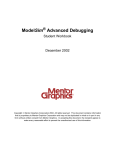
Overture Technical Report Series
No. TR-005
April 2013
Tutorial for Overture/VDM-RT
by
Peter Gorm Larsen
John Fitzgerald
Sune Wolff
Nick Battle
Kenneth Lausdahl
Augusto Ribeiro
Kenneth Pierce
Overture – Open-source Tools for Formal Modelling
Tutorial to Overture/VDM-RT
Document history
Month
Year
January 2010
March
2010
May
2010
February 2011
April
2013
Version Version of Overture.exe
0.1.5
0.2
1
0.2
2
1.0.0
3
2.0.0
ii
Contents
3
Overture Tool Support for VDM-RT: an Introductory Guide
3.1 Introduction . . . . . . . . . . . . . . . . . . . . . . . . .
3.2 Obtaining the Overture Tools . . . . . . . . . . . . . . . .
3.3 Using the Overture Perspective . . . . . . . . . . . . . . .
3.4 Mapping Between UML and VDM . . . . . . . . . . . . .
3.5 Debugging . . . . . . . . . . . . . . . . . . . . . . . . . .
3.5.1 The Debug Configuration . . . . . . . . . . . . .
3.5.2 The Debug Perspective . . . . . . . . . . . . . . .
3.5.3 Breakpoints . . . . . . . . . . . . . . . . . . . . .
3.6 Test coverage . . . . . . . . . . . . . . . . . . . . . . . .
3.7 Combinatorial Testing . . . . . . . . . . . . . . . . . . .
3.8 Realtime Log Viewer . . . . . . . . . . . . . . . . . . . .
3.9 Proof Obligations . . . . . . . . . . . . . . . . . . . . . .
3.10 A Command-Line Interface . . . . . . . . . . . . . . . . .
3.11 Summary . . . . . . . . . . . . . . . . . . . . . . . . . .
A A Car Navigation System Example
A.1 System Overview of the Car Navigation example
A.2 The Radio Navigation System Class . . . . . . .
A.3 The MMI Class . . . . . . . . . . . . . . . . . .
A.4 The Radio Class . . . . . . . . . . . . . . . . . .
A.5 The Navigation Class . . . . . . . . . . . . . . .
A.6 The Environment Task Class . . . . . . . . . . .
A.7 The Insert Address Class . . . . . . . . . . . . .
A.8 The Transmit TMC Class . . . . . . . . . . . . .
A.9 The Volume Knob Class . . . . . . . . . . . . .
A.10 The World Class . . . . . . . . . . . . . . . . . .
A.11 The Test Class . . . . . . . . . . . . . . . . . . .
iii
.
.
.
.
.
.
.
.
.
.
.
.
.
.
.
.
.
.
.
.
.
.
.
.
.
.
.
.
.
.
.
.
.
.
.
.
.
.
.
.
.
.
.
.
.
.
.
.
.
.
.
.
.
.
.
.
.
.
.
.
.
.
.
.
.
.
.
.
.
.
.
.
.
.
.
.
.
.
.
.
.
.
.
.
.
.
.
.
.
.
.
.
.
.
.
.
.
.
.
.
.
.
.
.
.
.
.
.
.
.
.
.
.
.
.
.
.
.
.
.
.
.
.
.
.
.
.
.
.
.
.
.
.
.
.
.
.
.
.
.
.
.
.
.
.
.
.
.
.
.
.
.
.
.
.
.
.
.
.
.
.
.
.
.
.
.
.
.
.
.
.
.
.
.
.
.
.
.
.
.
.
.
.
.
.
.
.
.
.
.
.
.
.
.
.
.
.
.
.
.
.
.
.
.
.
.
.
.
.
.
.
.
.
.
.
.
.
.
.
.
.
.
.
.
.
.
.
.
.
.
.
.
.
.
.
.
.
.
.
.
.
.
.
.
.
.
.
.
.
.
.
.
.
.
.
.
.
.
.
.
.
.
.
.
.
.
.
.
.
.
.
.
.
.
.
.
.
.
.
.
.
.
.
.
.
.
.
.
.
.
.
.
.
.
.
.
.
.
.
.
.
.
.
.
.
.
.
.
.
.
.
.
.
.
.
.
.
.
.
.
.
.
.
.
.
.
.
.
.
.
.
.
.
.
.
.
.
.
.
.
.
.
.
.
.
.
.
.
.
.
.
.
.
.
.
.
.
.
.
.
.
.
.
.
.
.
.
.
.
1
1
3
4
7
7
8
8
10
11
11
13
15
16
19
.
.
.
.
.
.
.
.
.
.
.
21
21
22
23
23
24
24
27
28
28
29
30
Chapter 3
Overture Tool Support for VDM-RT: an
Introductory Guide
Preamble
This is an introduction to the Overture Integrated Development Environment (IDE) and its facilities
for supporting modelling and analysis in VDM-RT the VDM extended language for modelling
real-time systems, formerly known as VICE (VDM in Constrained Environments). Since there is
not yet a book on VDM-RT it may be used as a substitute for Chapter 3 of “Validated Designs
for Object-oriented Systems”1 or as a free-standing guide. Additional material is available on the
book’s web site2 . Throughout this guide we will refer to the textbook as “the book” and the book’s
web site simply as “the web site”.
We use examples based on an in-car navigation case study and VDM-RT model presented in
Appendix A.
We introduce the features of Overture that support the combination of formal modelling in
VDM++ with object-oriented design using UML. This is done by providing a “hands-on” tour of
Overture, providing enough detail to allow you to use Overture for serious applications, including
the exercises in the book. However, this is by no means a complete guide to Overture3 ; more
information can be obtained from www.overturetool.org.
3.1
Introduction
In this chapter, an in-car radio navigation system which supports the Traffic Message Channel
(TMC) will used as example.
1
John Fitzgerald, Peter Gorm Larsen, Paul Mukherjee, Nico Plat and Marcel Verhoef. Validated Designs for Objectoriented Systems, Springer, New York. 2005, ISBN 1-85233-881-4.
2
www.vdmbook.com.
3
Note that the Overture tool suite support three different VDM dialects; VDM-SL (Specification Language), VDM++
and VDM-RT (Real Time) so although this tutorial illustrate how to use Overture with VDM-RT models you will see
multiple references to these dialects.
1
Tutorial to Overture/VDM-RT
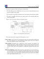
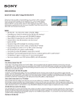
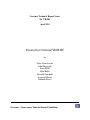
The system is composed of three main clusters of functionality;
• The Man-Machine Interface (MMI) takes care of user interaction such as handling key press
input and graphical display output.
• The navigation is responsible for destination entry, route planning and turn-by-turn guidance.
• The radio is responsible for basic tuner and volume control as well as handling traffic information from the TMC.
Figure 3.1 gives an overview of the in-car navigation system.
Figure 3.1: Car Navigation System Overview
The system must be able to support the following three use cases:
Change Volume: The user turns the rotary button and expects near instant audible feedback from
the system. Furthermore, the visual feedback (the volume setting on the screen) should be
timely and synchronized with the audible feedback.
Address Look-up: Destination entry is supported by a smart “typewriter” style interface. By
turning a knob the user can move from letter to letter; by pressing it the user will select the
currently highlighted letter. The map database is searched for each letter that is selected and
only those letters in the on-screen alphabet are enabled that are potential next letters in the
list.
TMC Message Handling: Digital traffic information is important for in-car radio navigation systems. It enables features such as automatic re-planning of the planned route in case a traffic
jam occurs ahead. It is also increasingly important to enhance road safety by warning the
driver, for example when a ghost driver is spotted just ahead on the planned route. TMC is
such a digital traffic information service.
2
CHAPTER 3. OVERTURE TOOL SUPPORT FOR VDM-RT: AN INTRODUCTORY GUIDE
When developing a Real-time model, it is adviced to create an object-oriented model first
outside the real-time domain. This will enable the developer to focus on the structure of the system
as well as eliminating any concurrency issues before moving on to the real-time domain. This
proposed process is described in much more detail in [?].
The rest of this chapter has the following outline; Section 3.2 describes how to obtain the Overture tools. Section 3.3 provides an initial introduction to the terminology used by Eclipse tools like
Overture. Section 3.4 shows how VDM-RT models can be connected to UML. Section 3.5 describes the process of testing and debugging VDM-RT models using Overture. Section 3.6 follows
up to show how test coverage information from the testing carried out can be produced and displayed directly in a pdf document generated using the LATEX text processing system. Section 3.7
shows how parts of the test process can be automated using Overture’s combinatorial testing feature. Section 3.8 goes on to show the Real-Time Log Viewer which gives a graphical presentation
of thread execution. Section 3.9 demonstrates the automatic generation of the additional checks
(called proof obligations) needed to ensure that a model is consistent. Finally, Section 3.10 illustrates how parts of Overture’s functionality can be accessed from a command line.
3.2
Obtaining the Overture Tools
In order to run the examples and exercises presented in the book, it is necessary to install two
separate tools – Overture and Modelio.
Overture: This is an open source tool, developed by volunteers and built on the Eclipse platform.
The project is managed on SourceForge4 . The best way to run Overture is to download a
special version of Eclipse with the Overture functionality already pre-installed. If you go to:
http://sourceforge.net/projects/overture/files/
you will find pre-installed versions of Overture for Windows, Linux and Mac5 .
Modelio: This is a tool that is both available in a commercial version as well as in an open source
setting from a company called Softeam. Just like Overture this tool is built on top of the
Eclipse platform. The product can be obtained from
http://www.modelio.org/.
A library of sample VDM-RT models, including all those needed for the exercises in the book,
is available and can be downloaded from the URL6 :
4
https://sourceforge.net/projects/overture/
It is planned to develop an update facility, allowing updates to be applied directly from within the Overture tools
without requiring a reinstallation. However, this can be a risky process because of the dependencies on non-Overture
components and so is not yet supported.
6
The library files are created to be used with Eclipse, but can be opened with file compression programs like Winrar
on Windows.
5
3
Tutorial to Overture/VDM-RT
http://overture.sourceforge.net/examples/ExamplesVDM_RT.zip
You can import the example library zip folder as described in Section 3.3. Finally, the web site
www.vdmbook.com contains all the examples used in this book as plain text files but these are
also all present in the above mentioned zip file. Finally, in order to make use of the test coverage
feature described in Section 3.6 it is necessary to have the text processing system called LATEX and
its pdflatex feature. This can for example be obtained from:
http://miktex.org/2.9/
R
Note for VDMTools
users. Overture provides a new open source VDM tool set, but it can also
R
work in conjunction with the VDMTools
tool set originally developed by IFAD A/S and now
maintained and developed by SCSK (see http://www.vdmtools.jp/en/). From Overture
it is also possible automatically to transfer a project over to VDMTools.
3.3
Using the Overture Perspective
Eclipse is an open source platform based on a workbench that provides a common look and feel
for a large collection of extension products. Thus if a user is familiar with one Eclipse-based
product, it will generally be easy to start using a different product on the same workbench. The
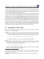
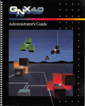
Eclipse workbench consists of several panels called views, such as the VDM Explorer view at
the top left of Figure 3.2. A particular collection of panels designed to assist a specific activity
is called a perspective. For example Figure 3.2 shows the standard Overture perspective which
contains views for managing Overture projects, and viewing and editing files. As we shall show
later, several other perspectives are avilable in Overture.
The VDM Explorer view helps you create, select, and delete Overture projects and navigate
between the files in these projects. Start by importing the car navigation project from the book’s
web site. This can be done by right clicking the project view and selecting Import, followed by
General → Existing Projects into Workspace. In this way the projects from .zip file mentioned
above can be imported very easily.
The panel to the right of the Explorer is the editor area. An editor customised to the dialect of
VDM being used in the project will appear here.
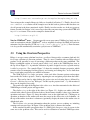
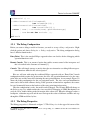
The Outline view, to the right of the editor (see Figure 3.3), displays an outline of the file
selected in the editor. It shows all declared classes, their instance variables, values, types, functions,
operations and traces. Figure 3.2 shows the outline view on the right hand side. Clicking on an
operation or function in the outline will move the cursor in the editor view to its definition. At
the top of the outline view there is a button to (optionally) display the items in the outline view in
alphabetical order.
The Problems view presents information about the projects you are working on, including
warnings and error messages. In Figure 3.2 the problems view is shown at the bottom.
In the standard Overture perspective there is a VDM Quick Interpreter view in a pane in the
same area as the problems view. This can be used for evaluation of standard VDM expressions
4
CHAPTER 3. OVERTURE TOOL SUPPORT FOR VDM-RT: AN INTRODUCTORY GUIDE
Figure 3.2: The Overture Perspective
Figure 3.3: The Outline View
independent of all VDM projects incorporated in your Overture IDE. This can be very convenient
to gain understanding of the different VDM operators. In Figure 3.4 it is possible to see how a
couple of expressions (typed in at the box at the botton of the view) are evaluated7 . Note that in
order to get a console where you are able to make use of definitions you need to use the console
launch mode as described in Section 3.5.1 below.
Most of the other features of the workbench, such as the menus and toolbars, are similar to other
Eclipse applications, though for newcomers to Eclipse it is worth noting that there is a special menu
with Overture-specific functionality. One convenient feature is a toolbar of shortcuts to switch
between different perspectives that appears on the right side of the screen; these vary dynamically
7
If errors appear in this evaluation the current version of the Overture IDE simply yield a Fatal error where it is
anticipated that later releases will provide more helpful run-time errors to the users.
5
Tutorial to Overture/VDM-RT
Figure 3.4: The VDM quick interpreter view
Figure 3.5: Explicit operation template
according to context and history.
When making corrections to the model, you can use the Overture IDE templates. When you
hit the key combination CTRL+space after entering the initial characters of the template needed,
Overture will offer possible completions. For example, if you type ”op” followed by CTRL+space,
Overture will propose the use of an implicit or explicit operation template.
The Overture IDE supports many templates for language constructs including cases statements, classes, quantified expressions, functions (explicit/implicit), operations (explicit/implicit)
and many more8 . Further templates can easily be added in the future. The use of templates makes
it more concenient to write VDM models without detailed prior knowledge of the language syntax.
When editing a VDM model, the Overture IDE parses the content of the editor buffer continuously as changes are made. If there are any syntax errors, these will be reported in the problems
view, as well as being highlighted in the editor. See the bottom of Figure 3.2. Each time a VDMRT model file is saved the editor type checks the model and reports any errors or warnings. Note
also that the suggestions made about missing characters in the error messages may not always be
entirely the action you may wish to take when correcting the source since the tool cannot guess
what you intended to write.
8
It is possible to see and enhance the complete list of these by selecting Window → Preferences → VDM → Templates.
6
CHAPTER 3. OVERTURE TOOL SUPPORT FOR VDM-RT: AN INTRODUCTORY GUIDE
3.4
Mapping Between UML and VDM
In order to map the UML class diagram created in Modelio to VDM, a new project must be created
in the Overture IDE to receive it. This is done by right-clicking in the VDM Explorer view, and
creating a new VDM-RT project and for example naming it CarRadioNavUML. If the desired
language dialect (say a VDM-RT project) is not directly available in the right-click menu, please
choose Project or Other and browse to the VDM-RT project. By right-clicking the new project
root in the VDM Explorer, UML Transformation can be chosen, followed by Import XMI. Now
browse to the XMI/XML file exported from Modelio called carradnavuml.uml and open this.
It is possible to automatically transform all the classes from the car radio navigation project
to UML. To do this, simply right click the project root and choose UML Transformation → Export XMI (i EMF UML3.0.0 format som .uml format). The UML/XMI file can subsequently be
imported in Modelio, enabling the user to get an overview of the complete model.
Note that state charts, activity diagrams, sequence diagrams, objects charts, package charts are
not used in the UML mapping. It is essentially only the information used statically inside classes
and their usage in class diagrams that is used.
3.5
Debugging
This section describes how to debug a model by testing it using the Overture IDE. The model can
be exercised by running the operations RunScenario1 or RunScenario2 in the World class:
class World
types
public perfdata = nat * nat * real
instance variables
static public envTasks : map seq of char
to EnvironmentTask := {|->};
operations
addEnvironmentTask: seq of char * EnvironmentTask ==> ()
addEnvironmentTask (pnm, penv) ==
( envTasks := envTasks munion { pnm |-> penv };
penv.Run() );
public RunScenario1 : () ==> map seq of char
to perfdata
7
Tutorial to Overture/VDM-RT
RunScenario1 () ==
( addEnvironmentTask("VolumeKnob",
new VolumeKnob(10));
addEnvironmentTask("TransmitTMC",
new TransmitTMC(10));
return { name |-> envTasks(name).getMinMaxAverage()
| name in set dom envTasks } );
...
end World
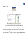
3.5.1
The Debug Configuration
Before you start to debug a model in Overture, you need to set up a debug configuration. Right
click the project and choose Debug As → Debug configuration. The debug configuration dialog
have 3 different launch modes:
Entry Point: This is the standard Eclipse approach where one decides before debugging which
operation/function to call.
Remote Console: This is an anvanced option that enables remote control of the interpreter and
this is described in the Overture user manual [?].
Console: This will simply start up a console where the user interactive can debug different operations/functions defined in the selected project9 .
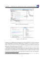
Here we will start with using the traditional Eclipse approach with an “Entry Point” launch
configuration which requires the project name, the class, the operation/function used as the entry
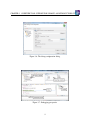
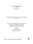
point of the test and the source file containing the entry point definition. As an example, Figure 3.6
shows the debug configuration for the car navigation model. The class and operation/function
name can be chosen from a Browse dialog. If the operation or function has arguments, these must
be typed in manually between the brackets of the entry point function/operation.
Once the configuration is ready, the model can be debugged. The Overture IDE will change to
the Debug perspective which contains the views needed for debugging in VDM. Breakpoints can
easily be set by double clicking in the left margin of the editor view. When the debugger reaches a
breakpoint, evaluation suspends and the user can inspect the values of different variables and step
through the VDM model line by line.
3.5.2
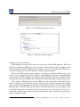
The Debug Perspective
The Debug perspective is illustrated on figure 3.7 The Debug view in the upper left corner of the
9
For VDMTools users this will be a familiar console corresponding to a VDM model that has been initialised in
VDMTools’ interpreter.
8
CHAPTER 3. OVERTURE TOOL SUPPORT FOR VDM-RT: AN INTRODUCTORY GUIDE
Figure 3.6: The debug configuration dialog
Figure 3.7: Debugging perspective
9
Tutorial to Overture/VDM-RT
Table 3.1: Overture debugging buttons
Button Explanation
Resume debugging
Suspend debugging
Terminate debugging
Step into
Step over
Step return
Use step filters
Debug perspective shows all running models and their call stacks. It also shows whether a given
model is stopped, suspended or running. All threads are also shown, along with their running
status. It is possible to switch between threads from the Debug view.
At the top of the view are standard Eclipse buttons (see Table 3.1) for controlling debugging,
allowing you to stop, step into, step over and resume.
The Variables view in the upper right corner of the Debug perspective shows all the variables
in a given context, when a breakpoint is reached. The variables and their displayed values are
automatically updated when stepping through a model.
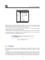
Figure 3.8: Breakpoint View
3.5.3
Breakpoints
The Breakpoints view gives an overview of all breakpoints set (see Figure 3.8). From this view the
user can easily navigate to the location of a given breakpoint, disable or delete them, or set their
properties.
The Expressions view allows the user to enter watch expressions whose values are automatically displayed and updated when stepping. Watch expressions can be added manually or created
by selecting create watch expression from the Variables view. It is possible to edit existing expressions. Like the Breakpoints view, this view is hidden in the upper right hand corner in Figure 3.7.
10
CHAPTER 3. OVERTURE TOOL SUPPORT FOR VDM-RT: AN INTRODUCTORY GUIDE
3.6
Test coverage
It is often useful to know how much of a model has been exercised by a set of tests10 . This gives
some insight into the thoroughness of a test suite and may also help to identify parts of the model
that have not been assessed, allowing new tests to be devised to cover these. When any evaluation
is performed on a VDM-RT model, the interpreter records the lines of the VDM-RT model that
are executed. This permits the line coverage to be examined after a test to identify the parts of the
VDM++ model that have not yet been exercised – coverage is cumulative, so a set of tests can be
executed and their total coverage examined at the end.
In our simple example, the different tests in the exercise above does cause the majority of
the VDM-RT model to be executed, but for demonstration purposes let us start by cleaning the
model (right click on the project and select Clean). Let us evaluate the RunScenario1 and
RunScenario2 operations where the Generate coverage option is selected. Remember
that whenever test coverage information is desired the Generate Coverage option must be
selected as shown in Figure 3.6. Once the debugger has completed and the result is written out
in the console it is possible to right click on the CarRadioNavi project and select the Latex
→ Latex coverage the coverage information that have been gathered in any expressions that have
been debugged since the last change to a file have been saved or the project have been cleaned will
be turned into a pdf file. The CarRadioNavi.pdf file is placed in the generated/latex
directory. Note that whenever the model is adjusted or it is cleaned so it gets type checked again
all the files in the generated directory are deleted.
The coverage information is provided in a way where uncovered expressions are shown in red
in the generated pdf file. In addition after the content of each VDM-RT source file a table with
coverage overview is provided in tabular form. So for example for the MMI class this looks like:
Function or operation Coverage
HandleKeyPress
90.0%
UpdateScreen
87.0%
mmi.vdmrt
88.0%
Calls
36
65
101
where the ExpertIsOnDuty and ExpertToPage operations are fully covered by just one call
(due to the fact that its body is simply one line) whereas the PlantInv operation is called twice11 .
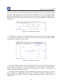
3.7
Combinatorial Testing
The previous sections have shown how to manually test and debug models that use an executable
subset of VDM-RT. However, Overture also contains a feature enabling more automation in the
testing process. It is possible to write regular expressions, as traces, that one would like to expand
10
11
Note that this feature is not yet supported for models using unicode characters such a Japanese identifiers.
Note that the coverage from the combinatorial testing feature described in Section 3.7 is not taken into account in the
current version of the Overture IDE, but this will be enabled in a later release.
11
Tutorial to Overture/VDM-RT
into a large set of individual tests. When new traces are incorporated in a VDM project you may
need to press the Refresh button ( ) in the CT Overview view.
In order to illustrate how this can be used, we have introduced a Test class which only in
introduced in this example for illustration purposes.
In order to do the automation, Overture needs to know about the combinations of operation
calls that you would like to have carried out, so it is necessary to write a kind of regular expression
called a trace. VDM-RT has been extended such that traces can be written directly as a part of a
VDM-RT model. In our case, inside the Test class one can find:
traces
TT: let x in set {1,2,3}
in
((mmi.HandleKeyPress(x,x) |
mmi.UpdateScreen(x,x) |
radio.AdjustVolume(x) |
radio.HandleTMC(x) |
nav.DatabaseLookup(x) |
nav.DecodeTMC(x));
EnvironmentTask‘IsFinished())
The let-be statements in the trace called TT yield all possible combinations of the variable bindings
to x (whereas manual debugging will select an arbitrary binding here). This is followed by the call
of 6 different operations seperated by an alternative operator (|). The selected x value is then used
as argument t each of these operations so in total this generates 18 (3 times 6) test cases. Inside
this combinatorial testing view you can select the CarRadNav project, right click it and choose
the Full Evaluation option as shown in Figure 3.9. Now Overture expands and executes all 18 test
cases one after each other. The results of these executions are illustrated with green check marks
and red crosses, meaning that the tests passed or failed respectively (see Figure 3.10). Note that in
the Combinatorial Testing perspective, the view in the lower region is able to show the individual
steps of a selected test case, along with the corresponding results from its four operation calls.
Note that here IsFinished have been defined in the EnvironmentTask class as:
public static IsFinished: () ==> ()
IsFinished() == skip;
sync
per IsFinished => #fin(logSysToEnv) > 0;
This is necessary because the operations being tested are all defined as being asynchronous and thus
12
CHAPTER 3. OVERTURE TOOL SUPPORT FOR VDM-RT: AN INTRODUCTORY GUIDE
the execution would complete before the system had a change to do its work if the IsFinished
operation was not used.
Figure 3.9: Invoking the combinatorial testing feature
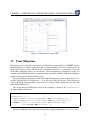
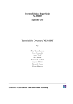
Figure 3.10: Using Combinatorial Testing for the Radio Navigation VDM-RT model
The syntax for traces also enables operation sequencing and repetition to be specified, but these
were not needed for this simple case. Using the full power of traces it is possible to efficiently
generate and execute very large test suites. Naturally, this is most likely to find inconsistencies
when the model attempts to define its essential predicates (invariants, pre and post-conditions).
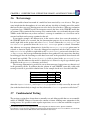
3.8
Realtime Log Viewer
When a VDM-RT model is being executed a textual logfile with information about the time of
the generation is created in a folder called ”generated/logs/debugconfig” with the .logrt
extension. Note that debugconfig here will be the name of the launch configuration that the
13
Tutorial to Overture/VDM-RT
user have created so if several launch confugurations are used these will be separated in different
directories. This logfile can be viewed in the build-in RealTime Log Viewer, by double-clicking
the file in the project view. The viewer allows you to explore system execution in different ways.
In Figure 3.11 the architectural overview of the system is given, describing the distributed nature
of the model.
Figure 3.11: Architectural overview
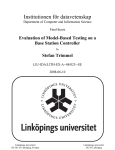
The RealTime Log Viewer also enables the user to get an overview of the model execution
on a system level – this can be seen in Figure 3.12. This view shows how the different CPUs
communicate via the BUSes of the system.
Figure 3.12: Execution overview
Since the complete execution of the model cannot be shown in a normal sized window, you
have the option of jumping to a certain time using the Go to time button. It is also possible to
export all the generated views to JPG format using the Export Image button. All the generated
pictures will be placed in the ”log” folder.
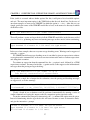
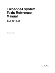
In addition to the execution overview, the RealTime Log Viewer can also give an overview
of all executions on a single CPU. This view gives a detailed description of all operations and
functions invoked on the CPU as well as the scheduling of concurrent processes. This can be seen
in Figure 3.13.
14
CHAPTER 3. OVERTURE TOOL SUPPORT FOR VDM-RT: AN INTRODUCTORY GUIDE
Figure 3.13: Execution on single CPU
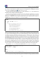
3.9
Proof Obligations
The Overture tool is also able to generate Proof Obligations automatically for VDM-RT models.
Proof obligations are boolean expressions that describe constraints to be met at various points in
the model in order to ensure that the model is internally consistent (i.e. no run-time errors will
occur while debugging if these are all satisfied). Proof obligations are generated to ensure, for
example, that operations will always respect invariants on instance variables. Each proof obligation
generated from a model should evaluate to true.
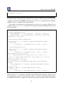
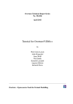
The proof obligation generator is invoked by right clicking on the project in the Explorer view
and then selecting the Proof Obligations -> Generate Proof Obligations entry. This will start up
a proof obligation perspective with a special PO view. For the alarm example this view takes the
form shown in Figure 3.14.
One of the first proof obligations listed for this example is related to the RunScenario1
operation, which is defined as:
public RunScenario1 : () ==> map seq of char to perfdata
RunScenario1 () ==
(addEnvironmentTask("VolumeKnob", new VolumeKnob(10));
addEnvironmentTask("TransmitTMC", new TransmitTMC(10));
return { name |-> envTasks(name).getMinMaxAverage()
| name in set dom envTasks } );
The proof obligation records the constraint that the mapping application envTasks(name)
15
Tutorial to Overture/VDM-RT
Figure 3.14: The Proof Obligation view for the Car Navigation VDM-RT model
is indeed defined (i.e. that the name is in the domain of the mapping envTasks). This is described as a proof obligation in the following form:
forall name in set (dom envTasks) &
name in set dom envTasks
Proof obligations represent checks that should be made on a model in order to gain confidence
in its consistency. At present, proof obligations have to be checked by manual inspection of the
model code. Tools are being developed for Overture to check as many as possible of the proof
obligations automatically, but there are always likely to be some that have to be checked manually.
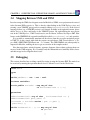
3.10
A Command-Line Interface
So far only the graphical user interface of Overture has been presented but the core of Overture
also provides a simple command line interface. This is useful for the automatic batch execution
of tests, though the command line also provides a full set of interactive execution and debugging
commands which can be useful when examining batch tests.
Overture is written in Java, and so to run it from the command line, the Overture jar file12
should be executed with a Java JRE (version 7 or later):
java -jar Overture-2.0.0.jar
12
See the Overture documentation at sourceforge.net/projects/overture for the location of the jar file or
use the script or windows bat file incorporating this.
16
CHAPTER 3. OVERTURE TOOL SUPPORT FOR VDM-RT: AN INTRODUCTORY GUIDE
If the jar file is executed with no further options like this, it will print a list of available options
and exit. The most important option is the VDM dialect that the tool should use. In the case of
our alarm example, we want to use VDM-RT for which the option is -vdmrt. After this, we can
simply specify the names of the VDM-RT model files to load, or the name of a directory in which
all the files reside:
java -jar Overture-2.0.0.jar -vdmrt CarNaviRadio
That will perform a syntax and type check of all the VDM-RT model files in the directory called
CarNaviRadio, producing any errors and warning messages on the console, before terminating:
Parsed 10 classes in 0.187 secs. No syntax errors
Type checked 12 classes in 0.094 secs. No type errors
In the case of our example, there are no syntax or type checking errors. Warnings can be suppressed
using the -w option.
If a VDM-RT model has no type checking errors, it can either be given an expression to evaluate
as an option on the command line, or the user can enter an interactive mode to evaluate expressions
and debug their execution.
To evaluate an expression from the command line, the -e option is used, followed by a VDM
expression to evaluate. You may also find the -q option useful, as this suppresses the informational
messages about the parsing and type checking:
java -jar Overture-2.0.0.jar -vdmrt -w -q -e
"new World().RunScenario1()" CarNaviRadio
This produces a single line of output for the evaluation, since the parsing and checking messages
are suppressed, as are the warnings:
{"TransmitTMC" |-> mk_(118187598, 118187598, 118187598),
"VolumeKnob" |-> mk_(36490730, 140915746, 6.2612283777777776E7)}
Clearly a batch of test evaluations could be performed automatically by running a series of
similar commands and saving the output results for comparison against expected results.
To run the command line interpreter interactively, the -i command line option must be given.
Instead of terminating after the type check, this will cause Overture to enter its interactive mode,
and give the interactive > prompt:
Parsed 10 classes in 0.172 secs. No syntax errors
Type checked 12 classes in 0.14 secs. No type errors
Initialized 12 classes in 0.109 secs.
17
Tutorial to Overture/VDM-RT
Interpreter started
>
From this prompt, various interactive commands can be given to evaluate expressions, debug their
evaluation, or examine the VDM-RT model environment. The help command lists the commands
available. The quit command leaves the interpreter.
For example, the following session illustrates the creation of a test object, followed by an
evaluation of its RunScenario2 operation, and a debug session with a breakpoint at the start of
the same operation:
> create world := new World()
> p world.RunScenario2()
= {"InsertAddress" |-> mk_(71646789, 71646789, 71646789),
"TransmitTMC" |-> mk_(118187598, 118187598, 118187598)}
Executed in 0.655 secs.
> break World‘addEnvironmentTask
Created break [1] in ’World’ (CarNaviRadio\World.vdmrt)
at line 12:5
12:
( envTasks := envTasks munion { pnm |-> penv };
> p world.RunScenario2()
Stopped break [1] in ’World’ (CarNaviRadio\World.vdmrt)
at line 12:5
12:
( envTasks := envTasks munion { pnm |-> penv };
[MainThread-164]> print penv
penv = InsertAddress{#77, max_stimuli:=10, e2s:={|->},
s2e:={|->},EnvironmentTask{#76, max_stimuli:=10, num:=0,
e2s:={|->},s2e:={|->}}}
[MainThread-164]> continue
Runtime: Error 4021: Duplicate map keys have different
values:
"InsertAddress" in ’World’ (CarNaviRadio\World.vdmrt)
at line 12:28
Stopped in ’World’ (CarNaviRadio\World.vdmrt)
at line 12:28
12:
( envTasks := envTasks munion { pnm |-> penv };
Notice that the print command is available at the breakpoint to examine the runtime state of
the system. In the example, we show the value of the penv variable. Continuing from this point,
the VDM-RT model raises a runtime error because the previous execution’s results are still in the
18
CHAPTER 3. OVERTURE TOOL SUPPORT FOR VDM-RT: AN INTRODUCTORY GUIDE
(static) envtasks map. The VDM-RT model can be re-initialized between runs with the init
command to avoid this.
The help command is context sensitive, and will list the extra debugging commands available
at a breakpoint, such as continue, step, stack, list and so on. The full set of commands
is described in the Overture User Guide13 .
3.11
Summary
This chapter has introduced the following major features of tool support for VDM-RT:
• syntax checking of VDM-RT models;
• type checking of VDM-RT models;
• executing and debugging VDM-RT models;
• combinatorial testing enabling automation of parts of the testing process;
• proof obligation generation and
• a command-line interface enabling access to test coverage.
13
Supplied with the Overture documentation.
19
Tutorial to Overture/VDM-RT
20
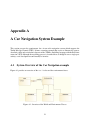
Appendix A
A Car Navigation System Example
This section presents the requirements for a in-car radio navigation system which supports the
Traffic Message Channel (TMC). It forms a running example that serves to illustrate the process
described earlier and to introduce elements of the VDM++ modelling language with the Real-time
extension VICE. Although the modelling process is described here as though it were a single-pass
activity, a real development would usually be iterative.
A.1
System Overview of the Car Navigation example
Figure A.1 provides an overview of the World class and the environment classes.
Figure A.1: Overview of the World and Environment Classes
21
Tutorial to Overture/VDM-RT
A.2
The Radio Navigation System Class
The RadNavSys class is the system class that all VDM-RT models must include.
system RadNavSys
instance variables
-- create an MMI class instance
static public mmi : MMI := new MMI();
-- define the first CPU with fixed priority
-- scheduling and 22E6 MIPS
CPU1 : CPU := new CPU (<FP>, 22E6);
-- create an Radio class instance
static public radio : Radio := new Radio();
-- define the second CPU with fixed priority
-- scheduling and 11E6 MIPS
CPU2 : CPU := new CPU (<FP>, 11E6);
-- create an Navigation class instance
static public navigation : Navigation := new Navigation();
-- define the third CPU with fixed priority
-- scheduling and 113 MIPS
CPU3 : CPU := new CPU (<FP>, 113E6);
-- create a communication bus that links the three
-- CPU’s together
BUS1 : BUS := new BUS (<CSMACD>, 72E3, {CPU1, CPU2, CPU3})
operations
public RadNavSys: () ==> RadNavSys
RadNavSys () ==
( -- deploy mmi on CPU1
CPU1.deploy(mmi,"MMIT");
CPU1.setPriority(MMI‘HandleKeyPress,100);
CPU1.setPriority(MMI‘UpdateScreen,90);
-- deploy radio on CPU2
CPU2.deploy(radio,"RadioT");
CPU2.setPriority(Radio‘AdjustVolume,100);
CPU2.setPriority(Radio‘DecodeTMC,90);
-- deploy navigation on CPU3
22
APPENDIX A. A CAR NAVIGATION SYSTEM EXAMPLE
CPU3.deploy(navigation,"NavT");
CPU3.setPriority(Navigation‘DatabaseLookup, 100);
CPU3.setPriority(Navigation‘DecodeTMC, 90)
-- starting the CPUs and BUS is implicit
);
end RadNavSys
A.3
The MMI Class
class MMI
operations
async
public HandleKeyPress: nat * nat ==> ()
HandleKeyPress (pn, pno) ==
( cycles (1E5) skip;
cases (pn):
1 -> RadNavSys‘radio.AdjustVolume(pno),
2 -> RadNavSys‘navigation.DatabaseLookup(pno)
end );
async
public UpdateScreen: nat * nat ==> ()
UpdateScreen (pn, pno) ==
( cycles (5E5) skip;
cases (pn):
1 -> World‘envTasks("VolumeKnob").HandleEvent(pno),
2 -> World‘envTasks("InsertAddress").HandleEvent(pno),
3 -> World‘envTasks("TransmitTMC").HandleEvent(pno)
end )
end MMI
A.4
The Radio Class
class Radio
23
Tutorial to Overture/VDM-RT
operations
async
public AdjustVolume: nat ==> ()
AdjustVolume (pno) ==
( cycles (1E5) skip;
RadNavSys‘mmi.UpdateScreen(1, pno) );
async
public HandleTMC: nat ==> ()
HandleTMC (pno) ==
( cycles (1E6) skip;
RadNavSys‘navigation.DecodeTMC(pno) )
end Radio
A.5
The Navigation Class
class Navigation
operations
async
public DatabaseLookup: nat ==> ()
DatabaseLookup (pno) ==
( cycles (5E6) skip;
RadNavSys‘mmi.UpdateScreen(2, pno) );
async
public DecodeTMC: nat ==> ()
DecodeTMC (pno) ==
( cycles (5E5) skip;
RadNavSys‘mmi.UpdateScreen(3, pno) )
end Navigation
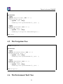
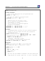
A.6
The Environment Task Class
24
APPENDIX A. A CAR NAVIGATION SYSTEM EXAMPLE
class EnvironmentTask
instance variables
-- use a unique identifier for each generated event
private num : nat := 0;
-- we limit the number of inserted stimuli
protected max_stimuli : nat := 0;
-- administration for the event traces
-- e2s is used for all out-going stimuli
-- (environment to system)
-- s2e is used for all received responses
-- (system to environment)
protected e2s : map nat to nat := {|->};
protected s2e : map nat to nat := {|->}
functions
-- checkResponseTimes verifies for each received response
-- whether or not the elapse time did (not) exceed the
-- user-defined limit
public checkResponseTimes: map nat to nat *
map nat to nat * nat -> bool
checkResponseTimes (pe2s, ps2e, plim) ==
forall idx in set dom ps2e &
ps2e(idx) - pe2s(idx) <= plim
-- the responses received should also be sent
pre dom ps2e inter dom pe2s = dom ps2e
operations
public EnvironmentTask: nat ==> EnvironmentTask
EnvironmentTask (pno) == max_stimuli := pno;
public getNum: () ==> nat
getNum () ==
( dcl res : nat := num;
num := num + 1;
return res );
-- Run shall be overloaded to implement the event generation
-- loop towards the system. typically, it starts a periodic
25
Tutorial to Overture/VDM-RT
-- thread
public Run: () ==> ()
Run () == is subclass responsibility;
public HandleEvent: nat ==> ()
HandleEvent (pev) == is subclass responsibility;
-- logEnvToSys is used to register when an event was inserted
-- into the system. Note that the ’time’ keyword refers to
-- the internal simulation wall clock of Overture
public logEnvToSys: nat ==> ()
logEnvToSys (pev) == e2s := e2s munion {pev |-> time};
-- logSysToEnv is used to register when an event was received
-- from the system. Note that the ’time’ keyword refers to the
-- internal simulation wall clock of Overture
public logSysToEnv: nat ==> ()
logSysToEnv (pev) == s2e := s2e munion {pev |-> time};
-- getMinMaxAverage calculates the minimum, maximum and
-- average response times that were observed during execution
-- of the model note that getMinMaxAverage is blocked until
-- the number of system responses is equal to the number of
-- sent stimuli termination is ensured because only a maximum
-- number of stimuli is allowed to be inserted in the system,
-- so eventually all stimuli can be processed by the system.
-- This method only works when each stimulus leads to exactly
-- one response, which is the case in this instance.
public getMinMaxAverage: () ==> nat * nat * real
getMinMaxAverage () ==
( dcl min : [nat] := nil,
max : [nat] := nil,
diff : nat := 0;
for all cnt in set dom s2e do
let dt = s2e(cnt) - e2s(cnt) in
( if min = nil then min := dt
else (if min > dt then min := dt);
if max = nil then max := dt
else (if max < dt then max := dt);
diff := diff + dt );
return mk_(min, max, diff / card dom s2e) )
26
APPENDIX A. A CAR NAVIGATION SYSTEM EXAMPLE
public static IsFinished: () ==> ()
IsFinished() == skip;
sync
-- getNum is mutually exclusive to ensure unique values
mutex (getNum);
-- getMinMaxAverage is blocked until all responses have
-- been received
per getMinMaxAverage => card dom s2e >= max_stimuli;
per IsFinished => #fin(logSysToEnv) > 0;
end EnvironmentTask
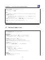
A.7
The Insert Address Class
class InsertAddress
is subclass of EnvironmentTask
operations
public InsertAddress: nat ==> InsertAddress
InsertAddress (pno) == max_stimuli := pno;
public HandleEvent: nat ==> ()
HandleEvent (pev) == logSysToEnv(pev)
post checkResponseTimes(e2s,s2e,24000000000);
public Run: () ==> ()
Run () == start(self); --,VolumeKnobT);
createSignal: () ==> ()
createSignal () ==
( dcl num2 : nat := getNum();
logEnvToSys(num2);
RadNavSys‘mmi.HandleKeyPress(2,num2) )
thread
periodic (2000,100,1000,0)
(createSignal)
27
Tutorial to Overture/VDM-RT
end InsertAddress
A.8
The Transmit TMC Class
class TransmitTMC
is subclass of EnvironmentTask
operations
public TransmitTMC: nat ==> TransmitTMC
TransmitTMC (pno) == max_stimuli := pno;
public HandleEvent: nat ==> ()
HandleEvent (pev) == logSysToEnv(pev)
post checkResponseTimes(e2s,s2e,40000000000);
public Run: () ==> ()
Run () == start(self); --,TransmitTMCT);
createSignal: () ==> ()
createSignal () ==
( dcl num2 : nat := getNum();
logEnvToSys(num2);
RadNavSys‘radio.HandleTMC(num2) )
thread
periodic (4000,400,3910,0)
(createSignal)
end TransmitTMC
A.9
The Volume Knob Class
class VolumeKnob
is subclass of EnvironmentTask
28
APPENDIX A. A CAR NAVIGATION SYSTEM EXAMPLE
operations
public VolumeKnob: nat ==> VolumeKnob
VolumeKnob (pno) == max_stimuli := pno;
public HandleEvent: nat ==> ()
HandleEvent (pev) == logSysToEnv(pev)
post checkResponseTimes(e2s,s2e,22000000000);
public Run: () ==> ()
Run () == start(self); --,VolumeKnobT);
createSignal: () ==> ()
createSignal () ==
( dcl num2 : nat := getNum();
logEnvToSys(num2);
RadNavSys‘mmi.HandleKeyPress(1,num2) )
thread
periodic (1000,50,500,0)
(createSignal)
end VolumeKnob
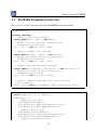
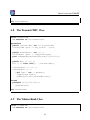
A.10
The World Class
class World
types
public perfdata = nat * nat * real
instance variables
static public
envTasks : map seq of char to EnvironmentTask := {|->};
operations
addEnvironmentTask: seq of char * EnvironmentTask ==> ()
addEnvironmentTask (pnm, penv) ==
( envTasks := envTasks munion { pnm |-> penv };
penv.Run() );
29
Tutorial to Overture/VDM-RT
public RunScenario1 : () ==> map seq of char to perfdata
RunScenario1 () ==
( addEnvironmentTask("VolumeKnob", new VolumeKnob(10));
addEnvironmentTask("TransmitTMC", new TransmitTMC(10));
return { name |-> envTasks(name).getMinMaxAverage()
| name in set dom envTasks } );
public RunScenario2 : () ==> map seq of char to perfdata
RunScenario2 () ==
( addEnvironmentTask("InsertAddress",new InsertAddress(10));
addEnvironmentTask("TransmitTMC", new TransmitTMC(10));
return { name |-> envTasks(name).getMinMaxAverage()
| name in set dom envTasks } );
end World
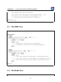
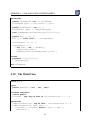
A.11
The Test Class
class Test
instance variables
mmi
: MMI
:= new MMI();
radio : Radio
:= new Radio();
nav
: Navigation := new Navigation();
traces
TT: let x in set {1,2,3}
in
((mmi.HandleKeyPress(x,x) |
mmi.UpdateScreen(x,x) |
radio.AdjustVolume(x) |
radio.HandleTMC(x) |
nav.DatabaseLookup(x) |
nav.DecodeTMC(x));
EnvironmentTask‘IsFinished())
30
APPENDIX A. A CAR NAVIGATION SYSTEM EXAMPLE
end Test
31