1
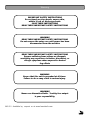
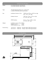
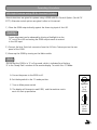
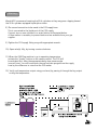
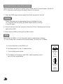
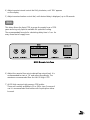
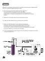
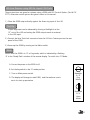
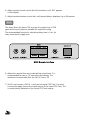
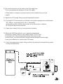
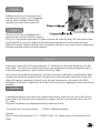
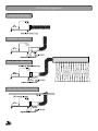
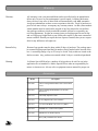
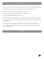
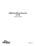
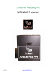
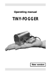
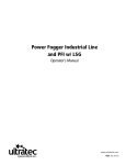
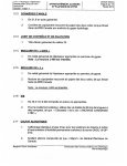
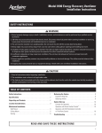
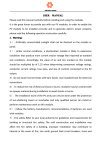
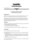
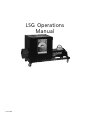
LSG Operations Manual v.12.15.00 Please Read Carefully Before Operating Table of Contents Page 1 Introduction Page 2 Warning Page 3 Technical Specifications Page 4 Operating Procedure Page 4 Part #CLF 2950 LSG High Pressure using 20 lb. Inverted Cylinder Page 7 Part #CLF 2950 LSG High Pressure using 50 lb. Cylinder Page 10 Part # CLF 2965 LSG Low Pressure using 350 lb. Liquid CO2 Tank Page 13 Low Pressure 350 Lb. Liquid CO2 Tank Page 14 Ducting Page 15 Troubleshooting Residual Buildup & Wet Output Page 17 LSG Ducting Suggestions Page 18 Alternate Control Methods Page 18 Recommended Fluids Page 18 Maintenance Page 19 Warranty Page 19 Accessories Page 20 Safety Precautions Page 20 Notes Page 21 Nationwide Carbon Dioxide Distributors Introduction Water Base Fog Technology Water Base Fog Technology is achieved by pumping a Glycol/ Processed Water mixture through a heat exchanger. The heat exchanger has been heated to the point where at the fog fluid mixture will vaporize. The fluids own vaporization forces the hot mixture out of the output nozzle where, when it mixes with the ambient air, it forms an opaque aerosol (fog). The fog is made up of tiny droplets of glycol that form around the small particles in the air. The suspended droplets reflect the light, which is why fog will take on the colour of the light illuminating it. LSG Low Fog Technology The patented "LSG" technology uses liquid C02 to the cool the fog, generating a consistent effect at sub zero temperatures. This process enables you to produce large quantities of low lying fog on a continuous basis without cue time limitations or the messy water residue associated with other technologies. The LSG is compact and mobile facilitating most applications. The unique partnering of a fog effect with liquid C02 is cost effective while providing a longer lasting effect. Designed to be utilized with the "LSG", the Le Maitre Genuine Molecular Fog Fluid provides a dry, thick, white effect with a consistent dissipation that eliminates any ambient hazing. The "LSG" couples with the Le Maitre G300, offering the most advanced controls and fog output available. The LSG consumes approximately 8 lbs. of Liquid Carbon Dioxide per minute of operation at 350 PSI. At the typical variflow setting of 20 the G300 will consume approximately ¾ of a gallon of fluid per hour constant. The system can be controlled via the standard digital remote control, DMX or show control. The DMX LSG Interface allows the LSG & G300 to be controlled on separate DMX channels. Standard equipment includes 12" ducting sleeve to facilitate standard ducting in many configurations based on fog distribution requirements. 1 Warning IMPORTANT SAFETY INSTRUCTIONS Do not touch or place hands, expose skin, within 10 cm. of discharge nozzle. SAVE THESE INSTRUCTIONS READ THESE IMPORTANT SAFETY INSTRUCTIONS WARNING READ THESE IMPORTANT SAFETY INSTRUCTIONS Do not remove the outer case until power has been disconnected from the machine READ THESE IMPORTANT SAFETY INSTRUCTIONS Persons suffering from asthma or allergenic sensitivity may experience irritation, discomfort, or allergic symptoms when exposed to heated fog effects WARNING Ensure that this unit is grounded at all times. Failure to do so may result in serious injury. WARNING Never use alternative fluids. Toxicity free output is your responsibility. M.S.D.S. Available by request or at www.lemaitrefx.com 2 Technical Specifications Model: Low Smoke Generator Low Pressure Low Smoke Generator High Pressure Type: CO2 Operated Fog chilling unit , couples with Le Maitre G300 Water Base Fog Generator Size: Installation Version w/ Cart: 159.38 cm x 63.5 cm. x 86.5 cm. high 62.5 x 25 x 34 high Roadcase Version: 104.5 cm x 71 cm. x 91.5 cm. high 41 x 28 x 36 high G300 Roadcase: 81 cm. x 71 cm. x 58.5 cm. high 32 x 28 x 23 high Weight: Installation version w/Cart:120 lbs. Roadcase version: 175 lbs G300 Roadcase w/ fluid: 200 lbs. Power Rating: 110 Volt A.C. 220 Volt A.C. 50/60 Htz. 20 Amps ( With G300 Fog Generator) 50/60 Htz. 10 Amp (With G300 Fog Generator) LSG Illustration 3 Operating Procedure LSG High Pressure using 20 lb. Inverted Cylinders These instructions are given for systems using a G300 with LSG Control Option (Part # CLF 2777). Alternate control options are given further in this manual. 1.) Place the G300 output directly against the foam ring input of the LSG. TechTip Proper alignment can be observed by shining a flashlight into the 12" exit of the LSG and noting the G300 output nozzle is centred in the LSG input. 2.) Connect the blue Twist lock connector from the LSG into Custom port on the rear panel of the G300. 3.) Power up the G300 by turning on the Mains switch. Note Ensure that the G300 is in G or Fog mode, which is indicated by a flashing 'G' in the Ready Flash window of the remote display. To switch into G Mode: A. Ensure the power to the G300 is off. B. Set the keyswitch to the G mode position C. Turn on Main power switch. D. The display will change to read G300, and the machine contin ues in its start up procedure. Keyswitch in G Fog Mode Keyswitch in H Haze Mode 4 4.) Adjust remote interval control dial fully clockwise, until 'DEL' appears on the display. 5.) Adjust remote duration control dial, until desired delay is displayed, up to 30 seconds.. Note This delay allows the liquid CO2 to purge the supply hose of CO2 gases ensuring only liquid is available for optimum cooling . The recommended formula for calculating delay time is 1 sec. for every three feet of supply hose. 6.) Adjust the remote flow rate to desired fog output level. It is recommended to start at '16' and adjust accordingly. The maximum recommended flow for the LSG High is '20'. 7.) A LSG High requires high pressure CO2 bottles. These are normally available in 20 or 50 lb. sizes. For ease of use it is recommended that bottles with liquid siphon tubes be used. If using 20 lb. bottles without the siphon tube, simply invert the bottles and place them in the bottle rack on those High pressure models so equipped. (If mobile bottle racks are necessary, they may be ordered using Part # CLF 2951.) 5 Warning We do NOT recommend inverting the 50 lb. cylinders as they may pose a tipping hazard. Use 50 lb. cylinders equipped liquid siphon tubes. 8.) The second connection to be made is the CO2 supply hose. This is connected to the liquid port of the CO2 supply. Connect two or more cylinders in a series fashion as illustrated below. A fibre washer is necessary to prevent leaks and are available from your gas supplier. 9.) Tighten the CO2 supply fitting snug with appropriate wrench . 10.) Open valve(s) fully, by turning counter-clockwise 11) When the G300 Fog machine is up to operating temperature, activate the 'Smoke' button on the remote control. The CO2 will be activated first. After the appropriate delay time passes smoke issue will start. You will know when the gas has been purged from the supply hose by the difference in noise that the LSG makes. 12.) Verify cool temperature output using your hand, by passing it through the fog output noting the temperature. 6 LSG High Pressure using 50 lb. Cylinders These instructions are given for systems using a G300 with LSG Control Option (Part # CLF 2777). Alternate control options are given further in this manual. 1.) Place the G300 output directly against the foam ring input of the LSG. TechTip Proper alignment can be observed by shining a flashlight into the 12" exit of the LSG and noting the G300 output nozzle is centered in the LSG input. 2.) Connect the blue Twist lock connector from the LSG into Custom port on the rear panel of the G300. 3.) Power up the G300 by turning on the Mains switch. Note Ensure that the G300 is in G or Fog mode, which is indicated by a flashing 'G' in the Ready Flash window of the remote display. To switch into G Mode: A. Ensure the power to the G300 is off. B. Set the keyswitch to the G mode position C. Turn on Main power switch. D. The display will change to read G300, and the machine contin ues in its start up procedure. Keyswitch in G Fog Mode Keyswitch in H Haze Mode 7 4.) Adjust remote interval control dial fully clockwise, until 'DEL' appears on the display. 5.) Adjust remote duration control dial, until desired delay is displayed, up to 30 seconds. Note This delay allows the liquid CO2 to purge the supply hose of CO2 gases ensuring only liquid is available for optimum cooling . The recommended formula for calculating delay time is 1 sec. for every three feet of supply hose. 6.) Adjust the remote flow rate to desired fog output level. It is recommended to start at '16' and adjust accordingly. The maximum recommended flow for the LSG High is '20'. 7.) A LSG High requires high pressure CO2 bottles. These are normally available in 20 or 50 lb. sizes. For ease of use it is recommended that bottles with liquid siphon tubes be used. 8 Warning We do NOT recommend inverting the 50 lb. cylinders as they may pose a tipping hazard. Use 50 lb. cylinders equipped liquid siphon tubes. 8.) The second connection to be made is the CO2 supply hose. This is connected to the liquid port of the CO2 supply. Connect two or more cylinders in a series fashion as illustrated below. A fibre washer is necessary to prevent leaks and are available from your gas supplier. 9.) Tighten the CO2 supply fitting snug with appropriate wrench . 10.) Open the Liquid valve(s) fully, by turning counter-clockwise 11) When the G300 Fog machine is up to operating temperature, activate the 'Smoke' button on the remote control. The CO2 will be activated first. After the appropriate delay time passes smoke issue will start. You will know when the gas has been purged from the supply hose by the difference in noise that the LSG makes. 12.) Verify cool temperature output using your hand, by passing it through the fog output noting the temperature. 9 LSG Low Pressure using 350 lb. Liquid CO2 Tank These instructions are given for systems using a G300 with LSG Control Option (Part # CLF 2777). Alternate control options are given further in this manual. 1.) Place the G300 output directly against the foam ring input of the LSG. TechTip Proper alignment can be observed by shining a flashlight into the 12" exit of the LSG and noting the G300 output nozzle is centered in the LSG input. 2.) Connect the blue Twist lock connector from the LSG into Custom port on the rear panel of the G300. 3.) Power up the G300 by turning on the Mains switch. Note Ensure that the G300 is in G or Fog mode, which is indicated by a flashing 'G' in the Ready Flash window of the remote display. To switch into G Mode: A. Ensure the power to the G300 is off. B. Set the keyswitch to the G mode position C. Turn on Main power switch. D. The display will change to read G300, and the machine contin ues in its start up procedure. Keyswitch in G Fog Mode Keyswitch in H Haze Mode 10 4.) Adjust remote interval control dial fully clockwise, until 'DEL' appears on the display. 5.) Adjust remote duration control dial, until desired delay is displayed, up to 30 seconds. Note This delay allows the liquid CO2 to purge the supply hose of CO2 gases ensuring only liquid is available for optimum cooling . The recommended formula for calculating delay time is 1 sec. for every three feet of supply hose. 6.) Adjust the remote flow rate to desired fog output level. It is recommended to start at '16' and adjust accordingly. The maximum recommended flow for the LSG Low is '25'. 7.) A LSG Low requires a 350 Lb. Low Pressure Liquid CO2 Tank. You must connect the supply hose to the Liquid output of the Liquid CO2 Tank. This is usually clearly indicated on the Liquid CO2 Tank outputs 11 8.) The second connection to be made is the CO2 supply hose. This is connected to the liquid port of the CO2 supply. A fibre washer is necessary to prevent leaks and are available from your gas supplier. 9.) Tighten the CO2 supply fitting snug with appropriate wrench . 10.) The Liquid CO2 Tank pressure as indicated on the pressure gauge must read between 300 - 340 psi to operate the LSG, this is achieved by opening the pressure builder valve at least one to three hours in advance of use by turning counter clockwise. 11.) Open Liquid valve(s) fully, by turning counter-clockwise 12) When the G300 Fog machine is up to operating temperature, activate the 'Smoke' button on the remote control. The CO2 will be activated first. After the appropriate delay time passes smoke issue will start. You will know when the gas has been purged from the supply hose by the difference in noise that the LSG makes. 13.) Verify cool temperature output using your hand, by passing it through the fog output noting the temperature. 12 Low Pressure 350 Lb. Liquid CO2 Tank The LSG Low Pressure uses CO2 Cylinders similar to the one pictured to the right. These are available from the local welding supply centre, or look in the Yellow Pages under Carbonics, and are sometimes referred to as Dewars. Typically there are three valve handles, a pressure gauge, and a CO2 level indicator located on the top of the Liquid CO2 Tank. These valves handles should be labelled as Gas/Vent, Liquid, and Pressure Builder. We will cover each of these below. Gas/Vent This is used if a CO2 gas supply is utilized. As we only use the liquid supply to operate the LSG, this valve is not opened. Liquid This is the source of our liquid supply of CO2. The LSG CO2 supply hose is threaded onto the valve outlet, being sure to use the appropriate sealing washer, and tighten to eliminate any leaks. When ready to operate the LSG, open the Liquid valve fully by turning counter clockwise. Pressure Builder The pressure builder is a very important component in achieving the proper LSG operating pressure. We can monitor this operating pressure by observing the pressure gauge located on the top of the Liquid CO2 Tank. Ideally the operating pressure of the Liquid CO2 Tank is 310 - 330 p.s.i.g. This is achieved by opening the pressure builder valve prior to operating the LSG. 13 TechTip Building the pressure to the proper level may take up to an hour, so it is suggested that the Pressure Builder valve be fully opened one to three hours before use. Note The Liquid CO2 Tank is equipped with a pressure relief valve that is fixed to open at 350 p.s.i.g. The pressure relief valve is in place to ensure the internal Liquid CO2 Tank pressure does not exceed 350 p.s.i.g. As you approach the ideal operating pressure the relief valve may open slightly and release CO2 gas. Although this is sometimes noisy this is no cause for alarm, simply close the pressure builder valve by turning clockwise. Ducting If ducting is required the LSG output requires a 12 flexible duct, and can be ducted up to 50 feet horizontally. The ducting is available insulated or non-insulated and can be purchased though an industrial supply company, or from Le Maitre (Part # CLF 2948). The LSG may also be ducted vertically up to 20 feet, to produce a waterfall or cascade effect. When ducting fog vertically,the remaining fog in the duct must not be allowed to backflow into the LSG. When this happens repeatedly the glycol in the fog may condensate on the inside of the G300, damaging the electronic components. See further in this manual for suggested solutions and ducting examples. TechTip If dividing the output to more than one location while ducting, make sure the sum of all cross sectional areas of the final duct sizes is equivalent or greater than the cross sectional area of the LSG 12 outlet. Doing this will prevent any backpressure being created by the LSG. The formula for cross sectional area: 0.78539 x (diameter squared) Example: The LSG outlet has a diameter of 12: 0.78539 x 144= 113 square inches is the area of the LSG outlet. 14 If you require 3 locations to duct the effect to, then the cross sectional area of the 3 ducts must be greater than 113 square inches. For this example, we will try a 8 diameter duct: 0.78539 x 64=50 If we multiply the cross sectional area of the 8 duct by 3 duct outlets : 50 x 3= 150. 150 is greater than 113 so the 8 ducting split into 3 ducts is acceptable. Some form of dampering may have to be used to balance the output of different sized outputs. Troubleshooting Residual Buildup & Wet Output The following list of items may cause wet output or residue to form. 1.) Low CO2 Pressure, less than 275 p.s.i.g. Check to ensure the Pressure Builder Valve is turned on and the pressure is over 300 p.s.i.g. before use. Monitor the pressure through the cue to see if the pressure does not drop below 275p.s.i.g.. If it does residue will begin to form. 2.) With the use of Mini Dewars this some times becomes a problem. Many Gas filling Stations do not correctly fill the Mini Liquid CO2 Tank and may cause them not to perform as well as large Dewars. This can be overcome by adding a High Pressure 20 pound cylinder or going to full size Dewars. 3.) The LSG in not connected to the Liquid side of the Liquid CO2 Tank. You must always use the Liquid CO2 from the Liquid CO2 Tank NOT the Vapour. 4.) If using ducting the duct may have a kink or some kind of obstruction in it. 5.) Fog machines nozzles are not straight out of the machine. These must be straight to ensure the fog can fully expand. Visually check the copper tubes at the G300 output to ensure the fog is exiting the output. If they are not, use a pair of pliers and adjust. (Be careful as they may be extremely HOT) 6.) Fog Machine is not lined up with the entry hole. This is where the G300 meets the LSG. If this does not meet direct and straight the fog can not expand fully. Take a flashlight and shine it through the 12" opening of the LSG and look through to the input to see if it is lined up properly. 15 7.) The G300 is not processing the fog properly. Remove the machine from the LSG, turn on the G300 and place your hand in the fog stream 24" away from the front of the machine. Your hand should be dry. You will feel a slight warming but do not confuse this for moisture. If the machine is not performing properly your hand will be very wet. The G300 should be serviced to rectify the problem. 8.) Too much fog is being pushed through the LSG. On the High Pressure LSG's we would recommend less then a 20 Flow Rate setting on the G300 remote on the Low Pressure LSG's we would recommend Less then a 25 Flow Rate setting on the G300 remote. 9.) Wrong Fluid is being used. Le Maitre Special Effects Molecular should be the only fluid used. Longer lasting fogs can cause this but again it is not observed often. If another manufacturers fluid is used this will definitely cause this type of problem. 10. The fresh air or the air inlets on the LSG are obstructed. This happens some time when things get moved around or items are placed on top of the LSG and drape over the inlet holes. Or the unit is placed too close to a wall or another piece of equipment. It can also happen if the LSG is installed in a very small room and no make up air is allowed to enter causing a vacuum within the room. This is also very rare but possible. 11. The LSG Valve is defective or damaged and is not allowing enough Liquid CO2 into the LSG. 12. The LSG is damaged and is not getting good air flow. 13. The internal air expanding unit is damaged or has come dislodged from it's mounting device. If you are experiencing a residue problem, and the above checklist has failed to solve the problem, please call Le Maitre Special Effects for assistance in rectifying the problem. 16 LSG Ducting Suggestions Horizontal Ducting Backflow Prevention Fog Curtain/Waterfall LSG with Stage Floor pocket 17 Alternate Control Methods If you are controlling your G300 by DMX 512, then it will be necessary to control the LSG with DMX 512. This can be achieved by using the DMX/LSG Interface Module (Part # CLF 2944). The DMX Data In and Data Out are 5 pin XLR style connectors to conform to the DMX 512 Protocol. Addressing is done by DIP switch using binary values. LSG / DMX Interface Part # CLF 2944 Recommended Fluids Molecular: The "Molecular Fluid" was originally designed for use in the LSX and LSG, however, many other applications were found very quickly. It is a clean, white, thick fog, practically odourless and dissipates as it begins to warm. Maintenance Exterior The exterior of the LSG requires only mild soap and water to clean. Interior The only interior maintenance required for the LSG is that the hose end of the Liquid Carbon Dioxide supply line be kept clean and free of debris. When not in use keep the supply line hose end capped or covered to prevent debris from entering and insects from nesting inside the line. 18 Warranty Warranty: All warranty is one year parts and labour unless specified and is on manufacturer defect only. Overuse or poor maintenance is not accepted. Le Maitre fluids must always be used. Any trace of other fluids will automatically void ALL warranties. Accept no substitutions as there are no exceptions to this rule. Proof of purchase or proof of sale must always accompany any warranty returns. An RA (return authorization) number must be noted on the outside of any box returned to our facilities. Any packages without a clearly marked RA number will not be accepted by our receiving department. Freight on warranty items are freight prepaid to our facility and we will prepay freight back to your facility after repair, by the most economical means available. Should you require the item express-returned, then you are responsible for any difference in freight cost. Return Policy: Return of any product must be done within 30 days of purchase. The package must be returned freight prepaid and the RA number clearly marked on the outside of the box. A restocking charge of up to 25% may be levied. Only credits are issued to the dealers account. Any product not returned within 30 days is considered purchased. Warning: Le Maitre Special Effects Inc. considers all it's product to be safe for use in the application it was intended. Le Maitre Special Effects takes no responsibility for misuse or incorrect use. Always refer to equipment owners manual for proper use. Accessories Model Description CLF 4000 LSG-L Touring Model Includes LSG & G300 Road Cases CLF 4025 LSG-H Touring Model Includes LSG & G300 Road Cases CLF 2779 LSG Delay Option for G300 CLF 2952 20 Foot High-Pressure Hose Extension CLF 2951 Co2 20 Pound Bottle Cart Carries 2 Cylinders CLF 2954 Manifold for 2 x Extra 20 lbs Cylinder CLF 2968 Mini Dewar 150 Pound Capacity Heavy Duty Automatic Floor Pocket 19 Safety Precautions 1. Ensure that operation of the machine is supervised by suitably trained and authorised personnel. 2. Do not modify the machine or use a machine which has been damaged in any way. 3. Allow sufficient air circulation around the machine at all times. 4. Protect the G300 from direct weather effects and wet locations. 5. Only use fluids recommended by the Manufacturer. 6. Do not continue to produce Fog output in an enclosed area when visibility is reduced below 50cm. 7. Avoid direct Fog output continuously at persons, structure or objects within close proximity of the discharge nozzle. 8. Ensure that adequate exhausting arrangements are available in the event of an emergency. 9. Do not place hands, or exposed skin within the first 10 cm of the discharge nozzle at any time during fog production. Notes 20 Nationwide Carbon Dioxide Distributors Praxair Canada 800-876-7729 USA 800-772-9247 Canada 514-933-0303 USA 800-820-2522 Air Liquide A database of Carbon Dioxide supplers is available at www.lemaitrefx.com Help us expand our Database by telling us who your local supplier is, E- mail: [email protected] 21