1
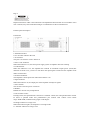
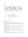
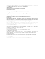
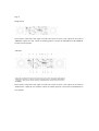
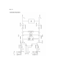
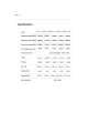
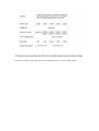
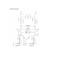
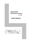
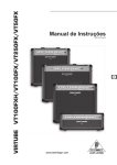
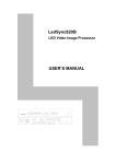
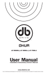
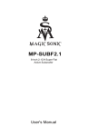
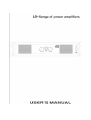
Page 1
Contents
Preface—
Important precautions—
Safety instructions
Function description
Ex-factory setting
H series front panel
H series front panel function introduction
H series rear panel
H series rear panel function introduction
Basic operation
Set up connection mode for H series
Reliability protection function
Application range
Maintenance and troubleshooting
Schematic illustration
Specifications
Page 2
WARNING
Please note:
4x8Ω speaker each channel High Output Power is about 1Ω
3x8Ω speaker each channel High Output Power is about 2Ω
2x8Ω speaker each channel High Output Power is about 3Ω
1x8Ω speaker each channel High Output Power is about 7Ω
Minimum Load is 2Ω, don’t use 4x8Ωspeaker each channel, you will destroy amplifier!
Longtime overload or overloaded input signal can destroy amplifier too
No warranty with unauthorized opening in electronic workshop or overloading
Don’t open. High Frequency and High Voltage inside, don’t touch speaker wires, risk of life!
Page 3
Preface
Thank you for purchasing H series amplifier. Please read the user’s manual carefully before you
use the product. It will give you correct guidance about using the product.
IMPORTANT PRECAUTIONS
1 Before using the product, please read the user manual carefully and retain it for further reference
2 Must use power supply same as the voltage label on the rear panel, the product will not be
guaranteed if for improper voltage used
3 The grounding cable of the equipment must be connected with the power supply grounding
cable. Please make sure the power supply grounding cable is connected with the ground
4 When this model is connected to the power supply, the standby LED is on. Some components
are connected to the electricity
5 At bridge mode, the output connector of amplifier should not be connected with the head of the
scope, or it will cause damage to the amplifier and the test equipment
6 The input level of the amplifier shall not be higher than the rated sensitivity value
7 Don’t connect the output of any channel with the input of another channel. Don’t parallel or
serial connect the output of one amplifier to the output of another amplifier
8 The power of amplifier must be 50%-100% higher than the rated power of speaker
9 Make sure the current using status of the amplifier is accordance with the input mode
10 Usually the volume control is set at -80db
11 If one signal has to be separated for several amplifiers, we suggest using signal distributor
12 Don’t obstruct the air entrance and air exit
13 Don’t use sine wave to test the power of amplifier, you will damage the amplifier
Page 4
Safety Instructions
Read all safety instructions before operating amplifier
Install equipment as follows:
Install it in a flat place
Keep the amplifier away from water or moisture
Place power amplifier away from heat sources, such as radiators or other heat source. Keep in
mind the following when connecting amplifier:
Read the user manual before connecting the amplifier
Connect each connection of the amplifier perfectly. If not, it may cause burn, damage, electric
shock in case of disconnection
To prevent electric shocks, do not open top cover
Connect the power cord with safety after check the AC power
Function Descriptions
This product applies for brand new tunnel heat-sink cooling system, which increases the heating
radiation efficiency and decreased working temperature of the amplifier
The amplifier module adopts Class H circuits, which increase the total efficiency to be 70% and
much power as the speakers in a limit space. Plus the product is equipped with DC, short circuit,
VHF, over-current and soft-start protection. These functions greatly increase the stability and
reliability of the products. The best loading condition for this series amplifier is at 8ohm
It adopts the output power to make sure that the amplifier is working under the rated power so as
to avoid the risk of damage because of over-loading
This amplifier is with advanced switching power supply, standing out the small volume and light
weight compared with same power products, favorable to save transportation cost and reduce
loading difficulties.
The output stage circuit adopts transistor collector output mode, which makes the transistors with
stronger loading ability. It is good for product stability
Ex-factory setting
1 All the volume adjustment button was set at”-80”
2 The power switch was set at “OFF”
3 Working mode selector switch was set at “STEREO”
4 Sensitivity selector switch was set at “26dB”
Page 5
Important direction: Other control functions and adjustment functions that do not introduce in the
user’s manual, may cause mechanical danger or radiation due to other outside factors.
H Series panel description
Front Panel
1 Installation Socket
Use to fix when install to the rack
2 Air Entrance
This part is air entrance. Don’t obstruct it.
3 Power “ON” Indicator
When this indicator is on, the main power supply system of amplifier has been working.
4 CLIP Indicator
When this indicator is on, the amplifier has reached its maximum output power (CLIP).The
distortion is about 0.5%, you have to turn down the input signal to make sure the amplifier work
under low distortion
5 Protection Indicator
The amplifier is under protection when this indicator is on
6 Signal Indicator
When this indicator on, the output port of the amplifier already has signals.
7 Power Switch
This switch is used for power on and off
8 Handles,
Handles are used for easy transportation
9 CH1 Volume control
In bridge mode, this potentiometer controls two channels volume, the CH2 potentiometer invalid.
In stereo or parallel mode: this potentiometer just controls CH1 volume. Gain control
range:-80dB~0dB, available turning angle is 280 degree.
10 Bridge indicator in orange color
When this indicator lights, the amplifier is on bridge mode
11 “Parallel” indicator in orange color
When this indicator illumes, the amplifier is on parallel mode
12 CH2 volume control
In bridge mode, this potentiometer invalid, the volume is controlled by CH 1 potentiometer. In
stereo or parallel mode, the potentiometer just controls CH2 volume. Gain control
range:-80dB~0dB, available turning angle is 280 degree.
13 Stand-by Power indicator
This indicator lights when the equipment is connecting with power. It will be off when the power
indicator lights.
Page 6-7
Rear panel
This is the right one. The one below is just used to show you the description
1 Air exit
This part is air exit. Don’t obstruct it.
2 Fuse Holder
The fuse holder includes a standard specification fuse inside. It is used to protect amplifier from
damage. If the amplifier was connected to power supply but the LED was not light, please check
the fuse situation. If you found the fuse broken, you must replace it with a fuse of same
specification.
3 CH1 binding post output
Red color connects to the positive port of speaker. Black color connects to the negative port of
speak. In bridge mode, just uses red color to connect the positive port of speaker.
4 CH1 SPEAKON output
This output socket (SPEAKON) is used to connect with speaker. Connecting: +1&+2, -1&-2.
5 Output socket in Bridge
Use the output socket to connect with the speaker, when the amplifier works in bridge mode.
Connecting: 1+ connects to the positive port of speaker, 1- connectors to the negative port of
speaker.
6 Operation mode selector
This switch is used to choose the operation mode of the power amplifier. Stereo mode: Two
channels are independently input and output. PARALLEL mode: Use CH1 to input signal
independently. Output independently from two channels” BRIDGE MODE: Use “+” of CH1 and
“+” of CH2 to input signal, output from 1+ and 1- of SPEAKON 3
7 Bridge indicator
The indicator lights when the amplifier is on bridge mode
8 Input Sensitivity selector
This selector allows to choosing the input sensitivity, 0.775v,1.0v,1.4v
9 CH1 bypass socket
It is parallel connection with XLR input of CH1, providing output signals same as the input
signals.
10 CH1 XLR input
This XLR input is balanced input. It connects to the upper audio processors
11 Power cord
This is the power supply cord. Before plug it into AC power supply, please connect to a power
plug which conforms to the power socket of local requirement. Meanwhile, please kindly check
whether the amplifier marked voltage is conform to local required voltage of not.
12 CH2 binding post output
Red color connects to the positive port of speaker. Black color connects to the negative port of
speaker. In bridge mode, just uses red color to connect the positive port of speaker.
13 CH2 output SPEAKON port
This output port (SPEAKON) is used to connect with speaker. Connecting: +1&+2, -1&-2. When
the amplifier is in bridge mode, this port is not in use
14 Grounding selector switch
You can use this switch to cut the “AC voice” when operating the system
15 30Hz high pass filter selector
This filter can cut the frequency below 30Hz to prevent low frequency signal getting into
amplifier and speaker, so as to save the energy consume of amplifier and protect the speaker
16 CH2 bypass socket
It is parallel connection with XLR input of CH2, providing output signal same as input signal
17 CH2 XLR input
This XLR input is balanced input. It is connected to the upper audio processors.
Page 8
Bridge Mode
In this mode, connect the CH1 input to sound source (such as mixer, CD) output, set the mode at
“BRIDGE” adjust the CH1 volume to suitable position, connect the SPEAKON of the BRIDGE
OUTPUT to the speaker.
In this mode, connect the CH1 input to sound source (such as mixer, CD) output, set the mode at
“PARALLEL” adjust the two channels volume to suitable position, connect the two SPEAKON to
two speakers.
Page 9
Protection
1 CLIP/LIMIT
It is used to prevent the speakers from dangerous clip signal. CLIP/LIMIT monitors the distortion
produced by amplifier output. When distortion exceeds 1%, Clip/limit will reduce the input signal
to ensure right signals from amplifier
Note: If the input signal already has CLIP or exceeds linearity working range of input circuit, the
CLIP/LIMIT will be invalid
2 Over-heat
If the amplifier works at full loading for a long time, and the fans have reached the highest speed.
If this status continue and the temperature rise up to over 95 degree, the amplifier will go into
over-heat protection status and the protection indicator (PRO) on the front panel will light on. The
amplifier will have no output when it is under PRO status. Therefore, the users are suggested to
correctly operate the amplifier, the loading should not be under 2ohm and maintain the airflow
good and free
3 VHF
If the amplifier output reaches a certain range and frequency exceeds 10Khz, such as MIC
feedback noise, amplifier may go into VHF protection after 3 seconds, the protection indicator
(PRO) on the front panel will be on and the speakers do not have sound, but it will recover
automatically after protection circuits startup for 10 seconds. If the output signal does not change,
it will keep on VHF protection
4 Short circuit protection
It makes the output transistors work at safe range. When output is in short circuit, the protection
indicator (PRO) on the front panel will be on and the amplifier has no output. The equipment will
be recovered after 10 seconds when the terms of short circuits removed.
5 AC local power protection
If the AC power voltage lower than the allowed working voltage (-160v), the power supply will be
turned off automatically until the power voltage is normal
6 DC protection
If the output signal has large DC voltage (=2.6V), in order to protect the speaker, the DC
protection circuit will be startup, the protection indicator (PRO) on the front panel will be on and
the amplifier has no output.
Maintenance and Trouble Shooting
Below are some simple methods to check if the amplifier has been damaged or not:
1 No output
If the signal LED is illumed based on the signal, the amplifier shall be fine, please check if the
SPEAKON output is well connected.
2 Low signal output
If the signal LED is illumed and clip LED lit, please check if the output port is short circuit
If the signal LED is illumed, and the protection LED is lit, the amplifier shall be at protection
stauts. There are two possibilities: one maybe over-heat protection, another maybe VHF protection.
Cancel the signal, you can test if it is VHF protection. If the amplifier chassis temperature is very
high, it should be over-heat protection. If the input voltage is too low, it may lead to lack of
voltage protection, the lowest AC voltage is 160V
3 If the failure is still existing after check the above, please return the equipment to the authorized
service agent, it should be repaired by skilled person
Page 10
Page 11
The above result was tested under the terms of standard power wave and constant voltage.