1
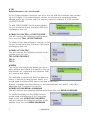
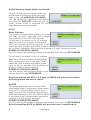
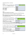
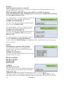
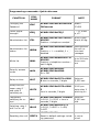
GSM-AUTO
GSM Controller
User manual
INDEX
Description................................................................................ 2
Preparing the SIM card............................................................... 3
Installation................................................................................ 4
Example connections.................................................................. 5
Programming commands............................................................. 7
Quick reference of programming commands …………..…………………….….12
Programming examples..............................................................13
Troubleshooting.........................................................................14
Thank you for purchasing our product. Please read this manual before starting
to install the GSM-AUTO. If you are unsure how to connect to the device you
wish to control refer to a qualified person
1
© GSM-AUTO
GSM-AUTO CONTROLLER
IMPORTANT!
Please read through this instruction manual before you start to install and
program the GSM-AUTO.
If you are unsure how to connect the device you wish to control refer to a qualified person.
Description
The GSM-AUTO is a wireless remote control on/off switch that connects to
the GSM cell phone network.
It has 2 independent relay switches, these can be programmed to switch on
or off for a pre-determined length of time whenever the GSM-AUTO is called.
The GSM-AUTO will recognise an authorised telephone number calling it and
action the call without answering. Therefore, there are no call charges incurred when calling it.
The relay switches can also be temporarily or permanently switched on or off
by sending the GSM-AUTO a text message command.
Requirements
The GSM-AUTO requires a 12 volt DC power supply capable of providing a
minimum current of 500mA, typical current consumption is 50mA
An active mobile phone SIM card with sufficient credit to send confirmation
text messages when programming the GSM-AUTO
GSM-AUTO SPECIFICATIONS
Operating Voltage
12 volts dc
Operating Current
Maximum 500mA, typically 55mA
Relay Contacts
2 x Normally Open and Normally Closed contacts
maximum switching capacity 10 amps @ 230V ac
per relay
GSM Frequency MHz
GSM-850, GSM-900, GSM-1800, GSM-1900
Humidity
Less Than 80% RH
Operating Temperature
-20°C to 55°C
Physical size
130 x 100 x 50 mm
Protection
IP65
Approvals
C.E
2
© GSM-AUTO
Preparing the SIM card
All new SIM cards have to be registered with the network provider before they
can be used, usually by calling the network provider or registering on their
website please refer to the instructions supplied with your SIM card.
During the registration procedure a confirmation code or text message is usually sent to the SIM cards telephone number, to be able to read and react to
the message you will need to insert the SIM card into an unlocked mobile
phone.
After successfully registering the SIM card, ensure there is sufficient credit on
the card for programming confirmation texts to be sent from the GSM-AUTO
unit.
You MUST ensure that the PIN request is disabled from the SIM card before
inserting it into the GSM-AUTO. If you do not disable the PIN request the
GSM-AUTO will not work. If the PIN request is not disabled and the unit is
switched on more than 3 times you will have to reset the PIN using the PUK
code which will have to be obtained from the service provider.
To check the PIN request status of your SIM card, place the card in an
unlocked mobile phone, switch the phone on. If you are able to make calls
without entering a PIN number the PIN request is disabled.
If a PIN number is requested refer to the instructions supplied with the SIM
card and then look through the phones options for the ‘disable PIN request’
and disable it.
You MUST disable any voicemail that is set up on the SIM card, the codes
shown below are for UK networks only, please refer to your network operator
if outside the UK
Vodafone: 1210 >Send - you will hear ‘order is accepted and confirmed’
O2 - Call 1760 >Send - you will hear ‘order is accepted and confirmed’
T-Mobile - Call 222 and follow instructions
Orange - Call 450 and follow instructions
The SIM card is now ready to use
We recommend that if you are using a ‘pay as you go’ (PAYG) SIM card that
you choose to automatically ‘Top-Up’ when the cards credit falls below a certain limit please contact your network provider or visit their website for more
details.
Most but not all PAYG SIM cards will be de-activated by the network if not
used to make an outgoing voice call or send an SMS text message within a
specific period. To prevent this simply send the GSM-AUTO a txt command, it
will reply by text message, do this once a month to keep the SIM card active.
3
© GSM-AUTO
Installation
Insert the SIM card, to access the SIM card carrier gently push the button adjacent to it, insert the SIM card and carefully close the carrier.
Connect a 12 volt DC power supply to terminals 1 & 2 ensuring positive is
connected to terminal 1, switch on the power supply, the red power LED will
light indicating power is present, the blue network LED indicator will initially
flash quickly, once logged onto the network it will flash more slowly approximately once every 3 to 4 seconds.
It is recommended that the GSM-AUTO be programmed to operate as required before final installation.
Connection details
If you are unsure how to connect the device you wish to control refer
to a qualified person
4
© GSM-AUTO
Example connections
Default settings
The default settings are, open access mode*, when the GSM-AUTO is called,
relay 1 switches on for 2 seconds, 2 seconds later relay 2 switches on for 2
seconds, the default password is 123456
* A call from any telephone number will activate the GSM-AUTO
Programming the GSM-AUTO
The GSM-Auto is programmed by sending it SMS text commands, these are
sent to the telephone number of the SIM card installed in the GSM-AUTO.
The password command must pre-fix all SMS text commands it is recommended the default password be changed.
Remember that all SMS text commands must always be sent using CAPITAL
LETTERS
DO NOT add spaces or any other characters
5
© GSM-AUTO
#PWD
Password
This command must always pre-fix any SMS text commands sent to the unit.
#PWDXXXXXX where xxxxxx is the six digit password.
The units default password is 123456 so initially #PWD123456 is entered
before the command, of course when you change the password you will prefix all commands with the new password
#CAP
Changing the Password
To change the password of the unit you
use the #CAP Command and to change
the password from the default 123456 to
121212 you would send the following SMS
text message to the unit.
#PWD123456#CAP121212#CAP121212
You will receive the following confirmation from the unit CAP:121212
IMPORTANT Please make a note of your new password, if you lose or
forget the password you will not be able to access the unit
We have now changed the password to 121212 and will use
this in the following examples
#CSQ
Check the signal strength
This command is useful to see what the GSM network signal strength is at the
location of the unit, it will report the signal strength in the range 0 to 31, a
minimum of 5 is required. If it is below 5 then it is advised to use an external
antenna.
To check the signal strength you would
send the following SMS text message to the
unit.
#PWD121212#CSQ?
You will receive the following similar confirmation from the unit CSQ<6>
#TEL
Administrator List
This is the command that allows you to add or remove the administrator telephone numbers that will receive text messages from the unit when the relays
are switched on or off using the #RLY and #RLOP commands.
If you wish to receive confirmation text messages that the relays
have been switched on or off you must enter your telephone number
into the Administrator list.
6
© GSM-AUTO
#TEL
Administrator List—continued
Up to 8 Administrator numbers can be in the list and the numbers can contain
up to 16 digits. If an administrator wishes to receive text messages whilst
abroad prefix the number with the country code for example if a UK number
+447827829595
To add 07827829595 to the administrator
list you would send the following SMS text
message to the unit.
#PWD121212#TEL1=07827829595
You will receive the following confirmation
from the unit TEL1=07827829595
To check all the administrator number in the
list you would send the following S.M.S text
message to the unit.
#PWD121212#TEL?
You will receive the following similar confirmation from the unit
TEL1:07827829595
TEL2:
TEL3:
#RERN
This is the command that allows you to enable, disable and check the status of the administrator list, these are the numbers that
will receive text alerts.
For example to allow only the first administrator in the list to receive text alerts, you
would send the follow SMS text command to the unit.
Where 1 enables the first position in the administrator list, and 0 (zero) disables the last 7 positions in the list.
#PWD121212#RERN=10000000
You will receive the following confirmation from the unit RERN:10000000
To check the status of the RERN list you
would send the following S.M.S text message to the unit #PWD121212#RER?
You will receive the following similar confirmation from the unit RERN:10000000
7
© GSM-AUTO
#WHL
White List
This is the command for adding to the white list authorised telephone numbers that can activate the unit.
By default the unit is set to open access mode and will be activated when it
receives a call from any telephone number. When the authorised numbers
have been added to the white list the unit should be set to secure access
mode using the #ACM2 command.
To add the number 07827829595 to the
white list in position 1, you would send the
following SMS text message to the unit. Note
only enter the last 8 digits as shown.
#PWD121212#WHL001=27829595
You will receive the following confirmation
from the unit WHL001:27829595
This is the first number in the White list and number 2 is sent as #WHL002=
and so on up to a maximum of 500 numbers.
Checking a number in the white list
To check the number in a position on the
white list, for example position 001 you
would send the following SMS text message
to the unit.
#PWD123456#WHL001?
You will receive the following confirmation
from the unit WHL001:27829595
Erasing a number is the white list
To erase a number in the white list you
would send the following SMS text message
to the unit.
#PWD121212#WHL001D
You will receive the following confirmation
from the unit WHL001-OK
#ACM
Security Access Mode
This command enables access security mode
so only the numbers programmed into the
white list can activate the unit and you
would send the following SMS text message to the unit.
#PWD121212#ACM2
You will receive the following confirmation from the unit ACM-ON
8
© GSM-AUTO
#ACM Security Access Mode—continued
To turn off the security access mode you
would send the following SMS text message to the unit #PWD121212#ACM0
You will receive the following confirmation
from the unit ACM-OFF confirming the security access mode is switched off and
open access mode is activated.
#GOT
Relay ON time
This is the command that allows you to set
the relay on times when the unit is called.
The maximum time is 65,535 seconds.
To set relay 1 to switch on for 15 minutes
each time the unit is called, the following
SMS text message is sent to the unit, 1 indicates the relay number and 00900 is the relay on time in seconds, this should be entered in 5 digit format as shown
#PWD121212#GOT1=00900
You will receive the following similar confirmation from the unit GOT1:00900
To set relay 2 to switch on for 10 minutes
each time the unit is called, the following
SMS command is sent to the unit, 2 indicates the relay number and 00600 is the
relay on time in seconds, this should be entered in 5 digit format as shown
#PWD121212#GOT2=00600
You will receive the following similar confirmation from the unit GOT2:00600
Note that setting the GOT 1 & 2 time to 00000 will prevent the relays
activating when the unit is called.
#GOTS
This command allows you to set a delay
time before relay 2 switches on after receiving a call. To set the delay time to 5 seconds, you send the following command by
SMS text message to the unit. Where 00005
is the delay time in seconds and should be
entered in 5 digit format as shown
#PWD123456#GOTS=00005
You will receive the following similar confirmation from the unit GOTS:00005
Note that setting GOTS to 00000 will prevent relay 2 switching on.
9
© GSM-AUTO
#GOT Relay ON time—continued
#GOT?
To check the relay on and delay times you
would send the following S.M.S text message to the unit #PWD121212#GOT?
You will receive the following similar confirmation from the unit.
GOT1: 00900
GOT2: 00600
GOTS: 00005
#RLY
Temporary switching on the relays
This command allows you to switch on the relays for up to 65,000 seconds
and receive confirmation SMS text messages when the relays switch on and
off
This command does not affect the #GOT1 or #GOT2 settings
Note: Confirmation text messages are only sent to telephone numbers
in the Administrators list
To activate relay 1 for 60 seconds you
would send the following SMS text message
to the unit, where 1 indicates the relay
number and 00060 is the on time in seconds, this should be entered in a 5 digit format as shown
#PWD121212#RLY1=00060
You will receive the following confirmation
text message from the unit RLY1=00060
when the relay switches on and you will receive the following message when the relay switches off RELY1-OFF
To switch on relay 2 for 5 seconds you
would send the following SMS text message
to the unit, where 2 indicates the relay
number and 03600 is the on time in seconds, this should be entered in a 5 digit format as shown
#PWD121212#RLY2=00005
You will receive the following confirmation
from the unit RLY2=00005 when relay 2
switches on and the following confirmation
when the relay switches off RELY2-OFF
10
© GSM-AUTO
#RLOP
Switching the relays on and off
This command allows you to switch the relays on and off and receive confirmation SMS text messages.
This command does not affect the #GOT1 or #GOT2 settings
Note: Confirmation text messages are only sent to telephone numbers
in the Administrators list
To switch Relay 1 on you would send the following SMS text message to the unit.
#PWD121212#RLOP1=1
You will receive the following confirmation
from the unit RLOP1=ON
To switch Relay 1 off you would send the
following SMS text message to the unit.
#PWD121212#RLOP1=0
You will receive the following confirmation
from the unit RLOP1=OFF followed by
RELY1-OFF
To switch relay 2 on and off use the commands #RLOP2=1 and #RLOP2=0
If you receive a RLOP1 Busy message the relay is already active via a previous command.
#RLY?
Checking the status of the relays
To check the status of the relays you
would send the following SMS text message to the unit
#PWD121212#RLY?
You will receive the following similar confirmation from the unit
RELAY1=00000
RELAY2=00000
RLOP1:OFF
RLOP2:OFF
*REST#
Resetting the unit
To reset the unit to the default settings you
would send the following S.M.S text message to the unit
*REST#121212 Note that the password prefix is not required
You will receive the following confirmation from the unit REST-OK the unit
has been reset to the default settings and the password will revert to 123456
11
© GSM-AUTO
Programming commands—Quick reference
FUNCTION
COMMAND
FORMAT
NOTE
Changing the
Password
#CAP
#PWD123456#CAPxxxxxx# Default
CAPxxxxxx
123456
Check signal
strength
#CSQ
#PWD123456#CSQ?
0 – 31, must
be >5
Administrator list #TEL
#PWD123456#TEL1=01827 Up to 8 num829595
bers & 16 digPosition > telephone number
its
Administrator list
#RERN
status
#PWD123456#RERN100000
00
Position > 1 = enabled, 0 =
disabled
White list
#WHL
#PWD123456#WHL001=27
Up to 500 tele829595
phone numPosition > telephone number—
bers
last 8 digits
Security access
mode
#ACM
#PWD123456#ACM2
#PWD123456#ACM0
On > Off
Relay on time
#GOT
#PWD123456#GOT1=0090
0 time in seconds, 5 digits
Maximum
65,535 sec-
Delay time between relay 1
and relay 2
switching on
#GOTS
#PWD123456#GOTS=0000
5
time in seconds, 5 digits
00000 prevents relay 2
switching on
#RLY
#PWD123456#RLY1=00060 Maximum
1=RLY1, 2= RLY2 > time in
65,000 secseconds, 5 digits
onds
#RLOP
#PWD123456#RLOP1=1
1=RLY1, 2=RLY2 > 1=ON,
0=OFF
Temporary
switching on relays
Switching relay 1
and 2 on or off
Resetting the unit *REST#
12
Administrators
who will receive text
messages
*REST#123456
Password preReset to default settings includ- fix not reing password
quired
© GSM-AUTO
Programming examples
Controlling a heating system
The simplest way is to wire terminals 7 and 8 on the GSM-AUTO to the terminals on your heating programmer that switch it on. When away from home
set the heating programmer to off. You can program the unit to switch on the
heating for say 2 hours when you call it.
Add the telephone numbers that you want to use to activate the unit.
To add the number 07827829595 to the white list in position 1, you would
send the following SMS text message to the unit. Note only enter the last 8
digits as shown.
#PWD123456#WHL001=27829595
Repeat for all the numbers you wish to add incrementing the WHL position by
one for each number, WHL002=, WHL003= and so on.
Switch on the security access mode so only the numbers in the white list can
activate the unit.
#PWD123456#ACM2
Set the relay on time to 2 hours.
#PWD123456#GOT1=07200
Controlling an automatic electric gate
Wire terminals 7 and 8 on the GSM-AUTO to the ‘start’ push button terminals
of the gate control panel.
Follow steps 1 and 2 above.
Set the relay activation time to 1 second.
#PWD123456#GOT1=00001
Do not use the gate control panels auxiliary power supply to power the GSMAUTO, use a separate power supply.
Ad hoc control of any device using only text messages
Switch on the security access mode, do not enter any numbers in the white
list.
#PWD123456#ACM2
Add your telephone number to the Administrator list.
#PWD123456#TEL1=01827829595
Enable your telephone number to receive confirmation text messages
#PWD123456#RERN10000000
Switch on the relays for a set amount of time (60 seconds in the example)
#PWD123456#RLY1=00060
1=RLY1, 2= RLY2 > time in seconds, 5 digits
Switch the relays on or off (Relay 1 switched on in the example)
#PWD123456#RLOP1=1
1=RLY1, 2=RLY2 > 1=ON, 0=OFF
13
© GSM-AUTO
Troubleshooting
1. Red power LED not alight
Ensure that your DC power supply is
connected correctly, positive (+) to
terminal 1 and negative (-) to terminal 2. Verify 12 volts is present using
a volt meter
2. Blue network LED flashing every
one second and not every 3 seconds
Ensure your SIM card has been activated and that the PIN request has
been disabled. If the unit is in a low
signal strength area consider using an
external GSM antenna or changing to
another network provider
Ensure your telephone number is in
3. I am not receiving confirmation test the Administrator list and that sending
messages when using the #RLY or
text messages to your number is en#RLOP commands
abled. See #TEL and #RERN commands
4. I am not receiving any text messages when initially programming the
unit
Ensure the unit is connected to the
GSM network by observing the blue
network LED, it should be flashing
once every 3 seconds (see 2 above)
Ensure the SIM card has credit
5. When I switch on the relays using
the #RLY or #RLOP commands and
the unit is called the relays are deactivated
This is the way the unit operates,
switch on the security access mode
#ACM2 so only numbers in the white
list can activate the unit
6. The unit occasionally activates by
itself
Network operators often make marketing calls to their subscribers,
switch on the security access mode
#ACM2 so only numbers in the white
list can activate the unit
7. The unit has been working for several months and has now stopped responding to calls and text commands
Most but not all PAYG SIM cards will
be de-activated by the network if not
used to make an outgoing voice call or
send an SMS text message within a
specific period. To prevent this simply
send the GSM-AUTO a txt command,
it will reply by text message, do this
once a month to keep the SIM card
active
The unit only sends relay status mes8. When I call the unit I do not receive
sages in response to the #RLOP and
a confirmation text message
#RLY commands
14
© GSM-AUTO