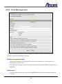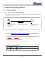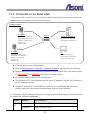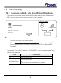
1
720P HD P2P H.264 CMOS Network Camera CAM741H-W-P / CAM741H-PoE-P User’s Manual Date: 7/5/2013 Firmware Version: V01.13.06.3521 Content Content ........................................................................................................................................ 1 1. Preface ................................................................................................................................. 3 2. Product Specifications........................................................................................................... 3 3. Product Installation ............................................................................................................... 6 3.1 Hardware Installation......................................................................................................... 6 3.1.1 Part Name .................................................................................................................. 6 3.1.2 Cable Connections ..................................................................................................... 7 4. Link to Camera from Smart Phone........................................................................................ 8 4.1 Install “iCam264e” for Android Mobile Device ................................................................... 8 4.2 Install “iCam264e” for Apple iOS Mobile Device ................................................................ 9 4.3 Using “iCam264e” App .................................................................................................... 10 5. Link to Camera from PC ..................................................................................................... 14 5.1 Monitor Setting ................................................................................................................ 14 5.2 Manually Assign IP Address ............................................................................................ 15 5.3 Live Video........................................................................................................................ 17 6. Configuration ...................................................................................................................... 21 6.1 Video / Audio ................................................................................................................... 22 6.1.1 Video Stream............................................................................................................ 22 6.1.2 Video (Advanced)..................................................................................................... 25 6.2 Camera ........................................................................................................................... 27 6.2.1 Camera Setting ........................................................................................................ 27 6.2.2 Privacy Mask ............................................................................................................ 29 6.3 Network ........................................................................................................................... 30 6.3.1 Network Setting ........................................................................................................ 30 6.3.2 Network (Advanced)................................................................................................. 32 6.3.3 DDNS ....................................................................................................................... 34 6.3.4 Wireless ................................................................................................................... 35 6.4 Event Handling ................................................................................................................ 37 6.4.1 Configuration ............................................................................................................ 37 6.4.2 Motion Detection ...................................................................................................... 40 6.4.3 Event Server ............................................................................................................ 42 1 6.4.4 GPIO ........................................................................................................................ 45 6.5 Storage ............................................................................................................................ 46 6.5.1 Storage Information .................................................................................................. 46 6.5.2 File List ..................................................................................................................... 48 6.6 System ............................................................................................................................ 49 6.6.1 System Information .................................................................................................. 49 6.6.2 User Management.................................................................................................... 50 6.6.3 Date / Time ............................................................................................................... 52 6.6.4 Maintenance............................................................................................................. 54 7. Network Configuration ........................................................................................................ 56 7.1 Intranet Only .................................................................................................................... 56 7.1.1 Connects to PC Directly ........................................................................................... 56 7.1.2 Connects to an Exist LAN ........................................................................................ 57 7.2 Internet Only .................................................................................................................... 58 7.2.1 Connects to ADSL with Fixed Public IP Address ...................................................... 58 7.2.2 Connects to ADSL with Floating Public IP (PPPoE) ................................................. 59 7.3 Intranet + Internet ............................................................................................................ 61 7.3.1 Connects to Internet with Fixed Public IP Address ................................................... 61 7.3.2 Connects to Internet with Floating Public IP ............................................................. 63 8. Factory Default ................................................................................................................... 64 2 1. Preface This camera is a 720P HD Mega-Pixel CMOS network camera which builds in web server. User views real-time video via IE browser. It supports H.264 and MJPEG video compression which provides smooth and high quality video. The PoE model built-in support for Power over Ethernet allows the camera to receive both data and power over a single Ethernet cable. This camera is an easy-to-use IP camera which is designed for security application. 2. Product Specifications Plug and Play function and dedicated app, easier for connection with smart phone Onvif compliance Mega-Pixel CMOS Sensor H.264 / MJPEG compression formats and six streaming Supports resolution up to 1280x720, 720P@30FPS real time Self-Contained HTTP Web Server providing Internet capability for remote access Day & Night functionality for 24-hours surveillance, auto activate IR illuminator in low illumination Infrared radiant distance up to 5 meters Wide Dynamic Range Exposure Time adjustment Day&Night Switch time control manually Wireless network connection (Wireless model) Built-in PoE splitter, support for Power over Ethernet (PoE model) Supports Micro-SD card for local event recording 2-way audio Online firmware upgrade Hardware Image Sensor 1/4” CMOS, Mega-Pixel Lens Board Lens, 3.6mm, F1.9 IR Distance 5 Meters Illumination Normal:1 lux IR On: 0 lux 3 Audio In Built-in microphone Audio Out Built-in speaker Power Supply Normal & Wireless model: DC 12V, 1A PoE model (built-in PoE Splitter): Use PoE: PoE Injector (IEEE 802.3af) Or, use Power Adaptor: DC 12V, 1A Power Consumption Max. 7 Watt Dimensions W64 x H95 x D45 mm Network Ethernet 10/ 100 Base-T Wireless (Wireless model) 802.11b/g/n, supports WPA-PSK, WPA2-PSK, WEP 64/ 128 bit Network Protocol HTTP, TCP/IP, RTP/RTSP, UDP, SMTP, FTP, Samba, PPPoE, DHCP, DDNS, NTP, UPnP, ARP Onvif Compliance Yes System Multiple Streaming Six streaming 3G Mobile View Yes, Live view / Record / Manage with Apple iOS and Android smart phone Video/ Audio Format Stream 1 Resolution: 1280x720 Frame Rate: up to 30FPS Video Format: H.264, MJPEG Stream 2 Resolution: 640x360 Frame Rate: up to 30FPS Video Format: H.264, MJPEG Stream 3 Resolution: 320x180 Frame Rate: up to 30FPS Video Format: H.264 Stream 4 Resolution: 320x180 Frame Rate: up to 30FPS Video Format: MJPEG Stream 5 Resolution: 160x128 Frame Rate: up to 30FPS Video Format: H.264 4 Stream 6 Resolution: 160x128 Frame Rate: up to 30FPS Video Format: MJPEG Video Bitrate Adjustment CBR, VBR Image Adjustment Brightness, Contrast, Hue, Saturation, Sharpness, De-noise, Gamma, White Balance, Exposure, WDR, ICR control mode, Video orientation Image Snapshot Yes Privacy Mask Yes, 3 different areas Motion Detection Yes, 3 different areas Event Trigger Motion Detection, Manually trigger, Boot up, IP changed Triggered Action Send Email, Send to FTP, Save to SD Card, Save to Samba HDD Security Password protection Firmware Upgrade HTTP mode, can be upgraded remotely Connection Up to 10 clients simultaneously Audio Yes, 2-way Micro-SD card / USB storage management Recording Trigger Motion Detection, Manually Trigger, IP Changed, Camera Boot up Video Format Video (AVI, MP4), Snapshot (JPEG) Web browsing requirement OS Windows XP, Vista, Windows 7 Web Browser Microsoft IE V7.0 (32-bit) or above, Mozilla Firefox V6.0 or above, Opera V11.5 or above, Safari V5.1 or above, Google Chrome V13.0 or above Suggested Hardware Intel Core 2 Duo 2.53GHz, RAM: 1GB Graphic card: 128MB onboard RAM * Specifications are subject to change without notice 5 3. Product Installation 3.1 Hardware Installation 3.1.1 Part Name Power Jack: To connect the DC 12V power adapter. Network Connector: The RJ-45 connector allows connect the Ethernet cable. Microphone: The built-in microphone to receive the voice. Speaker: The built-in speaker to play the voice from the remote PC. Micro-SD Card Slot: Allows insert a Micro-SD card to be the storage. USB Port (Available for wireless model): If the camera is wireless model, connect the included USB wireless dongle into this port. Or, connect to a USB flash to be the storage. Power LED: Indicates whether the power is ON/OFF. Network LED: Indicates the status of network access. Focus Ring: This ring allows adjust the focus. 6 3.1.2 Cable Connections Please refer to the figure below for the connection. Intranet (LAN) Camera in home Internet (WAN) Switch 3G Smart Phone The smart phone can install and use “iCam264e” app to link to The camera will be assigned the cloud server, and view or an IP address from router, manage the camera. and links to the cloud server automatically. ADSL Modem PC in home Router or IP Sharing The PC can use “IP Search” DHCP service is enabled program to find out the camera, and then link to it. 1. Make sure your router has enabled the DHCP service. 2. If the camera is Wireless model, plug the included Wireless dongle into camera. 3. Connect Ethernet cable to both camera and switch (or router). 4. Connect power adapter to turn on the camera. 5. The camera will be assigned an IP address from router, and links to the cloud server automatically. 6. A smart phone with Apple iOS or Android system can install “iCam264e” app, and use this app to add, view and manage the camera via the cloud server. Refer to the chapter Link to Camera from Smart Phone for the instruction. 7. A PC in the Intranet can install “IP Search” program, and use this program to find, view and manage the camera. Refer to the chapter Link to Camera from PC for the instruction. 7 4. Link to Camera from Smart Phone 4.1 Install “iCam264e” for Android Mobile Device Click on [Play Store] icon. Type “icam264e” in the Search line. When the App called “iCam264e” is found, click on it. Click on [ACCEPT] button to begin the installation. Click on [INSTALL] button. After the installation, an App icon named “iCam264” will be added. 8 4.2 Install “iCam264e” for Apple iOS Mobile Device Click on [App Store] icon. Type “icam264e” in the Search line. When the App called “iCam264e” is found, click on [INSTALL] button. 9 After the installation, an App icon named “iCam264” will be added. 4.3 Using “iCam264e” App Add Camera Click on [iCam264] icon. Click to begin adding camera. The QR code scanner will be launched. Move your phone aim to QR code on the rear panel of camera. Click on [Scan] button. The code will be scanned and put in “UID” line. Type the Security Code (admin), and change the name if necessary, then click on [OK] button. 10 The camera will be added and listed now. Setup Wireless Connection Click on the button beside camera name, and then click on [Edit Camera]. Click on [Advanced] button. Click on [Manage Wi-Fi networks] button. Plug out the Ethernet cable from camera, the camera will then connect to network through Wi-Fi connection. Click on the arrow button to select the Wireless router, and then type the password. Click on [OK] button to save the settings. 11 Live View Click on the camera name. The camera will be linked and display the live video. Click on this button to select: Mute – No voice. Click on this button to take a snapshot. Listen – listen the voice from camera’s microphone. Speak – Talk to the microphone of phone, the voice will be played from camera’s speaker. 12 Click on this button to change the video resolution. Click on this button and select the time to start the video recording. The button will be changed as the above during recording. Click on this button to list the recorded video clip or snapshot. Leave and Close iCam264e Click on the button on upper-right corner, and then click on [Exit]. Click on the [Leave] button to leave and close iCam264e. 13 On the list, select the video clip or snapshot to play. 5. Link to Camera from PC 5.1 Monitor Setting 1. Right-Click on the desktop. Select “Properties” 2. Change color quality to “Highest (32bit)”. 14 5.2 Manually Assign IP Address Always consult your network administrator before assigning an IP address to your camera in order to avoid using a previously assigned IP address. MAC Address: Each network camera has a unique Ethernet address (MAC address) shown on the sticker of the device. “Asoni IP Search” is a utility that provides an easier, more efficient way to configure the IP address and network settings of the network camera in Local Network (LAN). The software can be installed from the attached software CD. 1. Once “Asoni IP Search” has been successfully installed on the computer, double click the “Search CAM7 Series” icon on the desktop. 15 2. IP Search searches all the network devices which connect to the intranet and lists on the window. Click [Search] button to search again. 3. From the list, click and select the device with the MAC Address that corresponds to the device that is to be configured, and then click [Setup] button, the network configuration of this device will be shown. 4. Input “admin” and “admin” in Username and Password fields, and then filling in the IP Address, HTTP Port, RTSP Port, Subnet Mask, Gateway and DNS. 5. Click [Modify] button to save the settings into the device. 6. Wait for one minute to let the device update the settings, and then click [Search] button again to re-search the network devices. 7. If you want to view the device with IE browser, double-click the network device listed on the window, it will open an IE browser and connect to this device directly. 16 5.3 Live Video Start the IE browser, type the IP address of the network camera in the address field: http://<IP of camera> If the “HTTP Port” has been changed from “80”, type the URL as: http://<IP of camera>:<HTTP Port> After link to the camera, it will show a dialogue box. Key-in the user name and password to log-in and open the web page of camera. The default user name and password are “admin” and “admin”. For the first time to view the camera video via IE, it will ask you to install the ActiveX component. If the installation failed, please check the security setting for the IE browser. 1. If you want to view the device with IE browser, double-click the network device listed on the window, it will open an IE browser and connect to this device directly. 2. In IE, click on [Tools] [Internet Options…] 3. Click on [Security] Tab [Custom Level…] 4. In Security Settings, under [Download unsigned ActiveX controls], select “Enable” or “Prompt”. 5. In Security Settings, under [Initialize and script ActiveX controls not marked as safe], select “Enable” or “Prompt”. 6. When pop-up window with warning message, click [Yes] to save the settings. 1 2 17 3 4 5 When popup the following dialogue box, click [Yes]. The web page of the device shows as following. 18 ⑤ ① ② ③ ④ ⑥ Language : Change the display language. Configuration : Go into the configuration page to set the parameters if necessary. Select Stream : Select the video stream from the pull-down list to display it. Video Rotation : Select the orientation from the pull-down list to display the video. Status Bar : Shows video resolution, video refresh rate (FPS) and video bit rate. Function Buttons : Click these buttons will perform the following functions. Full Screen : Click this button, the video will change to full screen mode. Press [Esc] key or double-click the video again, it will back to normal mode. 19 Snapshot : Click this button to take snapshot of the video. The image will be saved to the indicated location that is defined with [File Location] button. Record : Click this button to record the video into the local PC. The video will be saved to the indicated location that is defined with [File Location] button. To stop recording, click this button again. The saved video format is AVI. The recorded file can be played by Microsoft Media Player. Note, H.264 decoder must be installed to play the recorded file. You can install “FFdshow” from the included CD for the decoder. Talk : The camera supports 2-way audio. Click this button, then you can use microphone which connected to the PC to talk to the camera side. Note, you can’t do “Talk” and “Listen” functions simultaneously, when “Talk” is ON, the “Listen” will be OFF automatically. Listen : Click this button to listen the audio from camera. Click again to turn off it. Note, you can’t do “Listen” and “Talk” functions simultaneously, when “Listen” is ON, the “Talk” will be OFF automatically. File Location : Sets the location where the video and snapshot are saved to. The default location is “C:\”. To change the location, click this button and select the desired location. Manual Trigger : Click the button to manually trigger an event when required. Note: an Event should be set before this feature can be used. Refer on how to setup an Event in Configuration Event Handling Configuration. 20 6. Configuration Click [Configuration] button to get into the configuration page. Click [Live View] button to back to the Live-View page. Sub-menu Main menu To open the page for configure, click the button on “Main menu” area on the left side, and then click the button on “Sub-menu” on the top side. Refer to the related chapter to configure the camera. 21 6.1 Video / Audio 6.1.1 Video Stream This device has in total 6 independent and simultaneous streams which can be used. The Live View page provides access to a list of streams which are set in this page. Stream Enabled Stream 2 ~ 6 can be enable or disable by check or uncheck this option. URL Sets the name for the video stream; input an appropriate name to indicate the stream type which is being used. The name will be listed in the Live View page for choose. If you want to get the video stream through RTSP protocol, include the name in the path, i.e. “rtsp://<Camera IP>/v01”. 22 Encode Resolution The resolution of all streams are fixed and can’t be changed. Encode Type You can select H.264 or MJPEG video compression for Stream 1 and 2. Note: the encode type of stream 3, 4, 5 and 6 are fixed and can’t be changed. Frame Rate This limits the maximum refresh frame rate per second. GOP GOP stands for "Group of Pictures". The GOP is a group of successive pictures within a coded video stream. JPEG Quality Values run from 1 to 80, the higher number the higher quality. Video Mode CBR: Defined as “Constant Bit Rate”, it’s the fixed bit rate allowed in the video stream. The data size of video stream will be limited under the value of “Bit Rate” field. You should set the value of “Bit Rate” depend on the upload bandwidth of network. VBR: Defined as “Variable Bit Rate”, it’s the fixed image quality of the video stream. The data size of video stream is no limitation, if the upload bandwidth of network is lower than the data size, the video will be displayed slowly. Enhanced CBR: Allows the video streaming be set between a fixed range of bit rate. Enhanced VBR: Sets the maximum bit rate and the range of image quality dedicated for the VBR. Bit Rate This is the bit rate allocated for transmitting the video. You should set the value of “Bit Rate” depend on the upload bandwidth of network, otherwise, the video will be displayed slowly. Target Bit Rate Max Sets the maximum bit rate allowed for the “Enhanced CBR” and “Enhanced VBR”. Reaction Delay Time 23 Available only for “Enhanced CBR”, sets the maximum time in milliseconds for which the Target Bitrate Maximum is allowed. Quality Level Sets the level of the image quality of video stream, the higher number the higher quality. The range of quality can be set by the Quality Level Max and Min. After set up, click [Save] to save the settings. 24 6.1.2 Video (Advanced) Enable Digital PT The Digital PT feature allows you pan, tilt around the image within a selected image area. The streams for using Digital PTZ are streams 2, 5 and 6 (such streams will be shown they are enable from the “Video Stream” page ( Configuration Video/Audio Video Stream.). Audio Setting Audio Out Volume Adjust the volume of the audio for a better audio level performance. Audio In Format 25 Select “u-LAW” or “Off” to enable or disable the audio input. The “u-LAW” is highly recommended for 3GPP mobile surveillance (for example, on iPhone or other network-enabled smart phones and NVR surveillance application software). OSD Setting Camera Name You can type a name into this field to identify this device (maximum of 20 characters). Date / Time Displays the date and time on the video. After set up, click [Save] to save the settings. 26 6.2 Camera 6.2.1 Camera Setting WB (White Balance) Enable and Disable the white balance adjustment for the image. Selections of Enable include manual selections based on the preferred method for the light conditions where the camera has been setup in. Exposure Configure the exposure settings to suit the image quality requirements in relation to 27 lighting, frame rate and bandwidth considerations. Exposure Time and Gain Control can be adjusted based on the specific need. Image Enhancement Image adjustments features may help on improving the image quality displayed. Mirror / Flip Turn ON or OFF these features if the installation of the camera requires the image to be mirrored horizontally or side flipped. Gamma Adjust the camera’s gamma correction if the light conditions require for such. ICR / LED ICR Auto Light Sensor: Sets the day/night to be switched at the Light sensor’s detection on the light conditions. Schedule: Sets the day/night to be switched within a specific time. ICR Manual Day: Always keeping in day environment (bright), no matter the Light sensor’s detection. Night: Always keeping in night environment (dark), no matter the Light sensor’s detection. B/W Mode By IR Type: Turns into black and white mode when the Light sensor detects it is dark, but turns into color mode when the Light sensor detects it’s bright. B/W: Displays the image always in black and white. Color: Displays the image always in color mode. Default Button Click [Default] button will load the default settings. 28 6.2.2 Privacy Mask Sets a privacy masking on the selected area; a maximum of 3 privacy masks are allowed. To enable the mask, make a checkmark on the box for enabling it, and after marking the area using the mouse, click on [Save Settings] button to make the changes permanent. 29 6.3 Network The Network Settings page allows the user to change and add more sophisticated configurations based on the network infrastructure where the Network Camera is installed. As for the IP Search utility is useful for initial boot up and straight network configuration, the Network Settings page offers a flexible way to fully utilize the network capabilities. Network Setting: Basic IP configuration settings. Network (Advanced): Page for network settings that include Time Server, Hostname and Port for services. DDNS: Service for accessing the Network Camera through domain names rather than IP addresses. Wireless: Configuration page wireless network settings. 6.3.1 Network Setting DHCP Service If this device behinds a router and the router provides DHCP service, using DHCP, this device will get all network parameters from the router automatically. Static IP Address Assign IP address, subnet mask, gateway, and DNS manually. IP Address: Specify a unique IP address for your network camera. 30 Netmask: Specify the mask for the subnet the network camera. Gateway: Specify the IP address for the Gateway. DNS 1: Specify the IP address for the first group of DNS. DNS 2: Specify the IP address for the second group of DNS. PPPoE The PPPoE feature enables the user to connect the Network Camera directly to the ADSL Modem having direct access to Internet. Click on the PPPoE Enable box to activate the feature, and enter the Username and respective Password. The Username and Password, as well as the internet service that goes with the ADSL Modem are provided by an Internet Service Provider (ISP) such as your local telephone company. Contact your ISP for more information on how to acquire such service. After set up, click [Save] to save the settings. 31 6.3.2 Network (Advanced) NTP Configuration Use the following NTP server address: Enter the host name or IP address of the NTP server. Note: For users using PPPoE as their network access, any change made to the “Network address” of the “NTP Configuration” may cause the screen to remain still for a while, because your local ISP (Internet Service Provider) is assigning new IP address and new values for the HTTP, RTSP and FTP ports, whenever a change is made to NTP through PPPoE. Enable HTTP The default HTTP port number 80 can be changed according to the user’s need. This is useful for simple security port mapping. Enable RTSP The RTSP protocol allows a connecting client to start an H.264/MJPEG stream. The default setting is 554. Enable FTP The FTP server running in the network cameras enables the upload of new firmware, 32 and user applications. Check the box to enable the service. Enable UPnP/ Enable UPnP Transversal This device supports UPnP, if the UPnP service is enabled on your computer, the device will automatically be detected and a new icon will be added to “My Network Places”. Note: To use “UPnP function”, the UPnP service must be enabled on your computer. To use “UPnP Transversal” function, the router must equips “UPnP Transversal” or “UPnP Port Forwarding” function too. Enable ARP/Ping Enabling Arp/ Ping will offer an additional tool to the user in order to detect the status of the Network Camera. For related commands to ARP/ Ping, refer to your Network Administrator. RTSP settings Anonymous: Allows the access of the RTSP streaming without authenticating. Authentication: Requires an authentication of username and password for retrieving the RTSP streaming. After set up, click [Save] to save the settings. 33 6.3.3 DDNS The DDNS (Dynamic Domain Name Service) feature allows users to access the Network Camera without the need of remembering the IP address, but rather using a name. For example: http://www.mycamera.com To be able to use the DDNS feature, a domain name must be registered first in a domain name service from a 3rd party service provider, such as DynDNS (www.dyndns.org). The DDNS feature only forwards the information between the Host Name server and the Network Camera, therefore the Username and Password must be obtained from the 3rd party service provider before using the feature. Note: Refer to your Domain Name Service Provider for more information on setting up a domain name. Some Domain Name Service providers charge a fee for the registration, while some offer the service as free of charge. It will be in the user’s decision which service to acquire. In order to use the DDNS feature, it is assumed that the Network Camera already has direct access to Internet. For more information on how to allow the Network Camera to access the Internet, consult with your Network Administrator. After set up, click [Save] to save the settings. 34 6.3.4 Wireless When using the wireless network for the first time, users must conduct the following setup: 1. The camera remains wired to a network switch/router through an Ethernet cable. 2. Click on “Enable Wireless” and the Wireless settings will be ready from being set. 3. Once the setup is completed, click on Save and unplug the Ethernet cable from the camera. Wireless Setting When you click on [Search] button, the network camera will detect the Access Points available in the current network. Enable Wireless The wireless function is disabled by default; enable the wireless mode in case a wireless connection is desired rather than the wired connection. In order to avoid network conflicts, it is recommended that the wireless IP address be different from the wired connection. 35 Network type Master/Slave: Select this to enable the wireless function for which it may function under a wireless connection infrastructure such as an Access Point. Ad-Hoc: Select this to enable a point-to-point connection to a computer. Host-AP: Select this to allow devices such as computers or mobile phone with Wi-Fi connectivity in order to setup directly the camera without connecting it to an Access point. SSID Choose a Wireless network from the SSID table, and type the SSID in the box. The SSID is case-sensitive. Security The encryption will depend on whether the Access Point (Wireless Router) utilizes an encryption key to authorize and authenticate client connections to access the wireless service. Select the security mode to match the Wireless network. It supports “None”, “WEP”, “WPA-PSK”, “WPA2-PSK” security encryption based on the setting of Router. Network Setting The default HTTP port number 80 can be changed according to the user’s need. This is useful for simple security port mapping. DHCP Service If the Access Point (Wireless Router) provides DHCP service, using DHCP, this device will get all network parameters from the router automatically. Static IP Address Assign IP address, subnet mask, gateway, and DNS manually. IP Address: Specify a unique IP address for your network camera. Netmask: Specify the mask for the subnet the network camera. Gateway: Specify the IP address for the Gateway. After set up, click [Save] to save the settings. 36 6.4 Event Handling This function allows the user to customize the Network Camera to perform actions during a period of time, upon the occurrence of certain events in order to have a result. For example: Capture a snapshot, at anytime, when a motion is detected; and send the snapshot to an email address. In simple words: Upon some condition, during a time, do something with a result. The condition can be set in “Trigger by” section. The period for detecting trigger can be set in “Trigger Time Settings” section. The action when event is triggered can be set in “When Triggered…” section. 6.4.1 Configuration 37 Trigger Event List Displays the current Event List saved permanently in memory. Add: In order to turn on the capability of setting an Event, click on [Add] button to add the available options. Note: the maximum number of events is limited to 10. Delete: In order to remove any existing event, click on the name of the Event and click on [Delete] button. Trigger Event Setup General Settings Event Name: Input a name to identify the Event that will perform the action upon some event occurrence. Trigger by (Condition): Continuous Trigger: The trigger condition is always on. Motion Detection: It will perform an action upon a motion is detected. Select which Motion Detection area should be detected. Manual Trigger: Sets the trigger event to be activated manually from the Live View page. The activation is done by a click on the icon of Manual Trigger. By Boot: It will perform an action when the camera is booted or restarted. This feature is useful to detect reconnections that are not anticipated or expected. When IP Change: Makes a notification when the IP address of the camera changes. Trigger Time Settings Always Trigger: Always keep the Network Camera alert to wait for some condition to happen. Set the trigger execution time: It will perform the action only for the time frame set. Drag the mouse upon the day and time to set the desired time. Stop Trigger: Don’t do anything while activated. In other words, even if the condition has happened the Network Camera shall not do anything. When Triggered... (Do some action when event is triggered) Upload Images: Sends the images to a predefined FTP server set in Configuration Event Handling Event Server page. Send Email notification: Send an email message to a predefined email address set in Configuration Event Handling Event Server page. 38 Send HTTP notification to: Send a text message as a parameter to predefined HTTP server set in Configuration Event Handling Event Server page. The HTTP server should be expecting a text message or a command. Send TCP notification to: Send a text message as a parameter to predefined TCP server set in Configuration Event Handling Event Server page. The TCP server should be expecting a text message or a command. Record to Storage: Record video (selected stream) to the connected storage. The storage must be indicated in Configuration Storage Storage Information.page first. Snapshot to Storage: Take snapshot and save to the connected storage. The storage must be indicated in Configuration Storage Storage Information.page first. After set up, click [Save] to save the settings. 39 6.4.2 Motion Detection Video motion detection is used to generate an alarm whenever movement occurs in the video image. A total of 3 areas can be configured. Once configured, the video motion detection windows appear in the list of available triggers, for triggering events. Note: Using the motion detection may decrease the camera’s overall performance. Don’t set Date & Time of OSD (On-Screen Display) included in the detected area. 40 Motion Detection List 3 areas can be set for which they will be identified in 3 colors each, Red, Green or Blue. Add: Once click this button, according to the color selected, a squared block will be displayed on the video. Drag the corner of block to adjust the size. Drag the name of the block can move its position. Delete: In case any of the area is not required, click on the name of the Area Name from the Motion Detection List, and click on [Delete] button. Motion Detection Setup Windows Area Name: Descriptive name of your choice. Sensitivity: For which the higher the number, the more sensitive is the motion area. Color: 3 colors can be chosen among the areas set for the motion detection; Red, Green or Blue. Once the process has been completed, click [Save] to save the settings. 41 6.4.3 Event Server Event Servers are used to receive uploaded image files and/or notification messages. To set up Event Server connections in your camera, enter the required information for the required server type. Add FTP: Adds a FTP server to receive the images. Add SMTP: Adds an Email address to receive email messages. Add HTTP: Adds a HTTP server to receive text messages. Add TCP: Adds a TCP server to receive text messages. Delete: To remove any existing Event Server, select a Name from the Event Server List and click on [Delete] button. Upon clicking on any button to add FTP, HTTP, TCP or SMTP server a box will show up for filling the required information. FTP Server 42 SMTP Server HTTP Server 43 TCP Server After set up, click [Save] to save the settings. 44 6.4.4 GPIO This page is used to ON/OFF the LED indicators on the front panel. Enable “Control LED lights on the Camera”: The LED on the front panel will be light to indicate the status. Disable “Control LED lights on the Camera”: The LED on the front panel will be OFF. After set up, click [Save] to save the settings. 45 6.5 Storage 6.5.1 Storage Information This page allows selecting the storage to store the video or image, lately used in the Event Handler feature. SD Displays information on the Micro-SD Card inserted in the network camera. Disk Format: Formatting the Micro-SD card by the Web user interface of the [Format] button is required before using it. (Note: all files present in the Micro-SD card will be permanently deleted. Back-up the files before formatting the card.) Duration: The duration of the recording in the Micro-SD card can set directly, values are measured in seconds Note: Accepted Micro-SD cards need to be within the 2GB and 32GB. After insert a Micro-SD card, it is required rebooting the camera for it to detect the card. Depending on the Device Class of the Micro-SD card, the detection may require 20~120 seconds. 46 Samba Files can also be stored directly into a File Server. Before configuring the IP Address, Path of the File server where the files will be stored, make sure the Username and Password have read/write rights to perform the access of the files into the File Server. After set up, click [Save] to save the settings. 47 6.5.2 File List This page displays the list of files which are stored in the Micro-SD Card. User can find the needed files by configuring the duration (between Start time and End time) and clicking on [Search] button. 48 6.6 System 6.6.1 System Information This page displays information about the current status of the Network Camera. Such information is useful to have references when direct information is required without going through the different pages of configuration of the Network Camera. User can type a name and location into “Device Name” and “Device Location” fields to identify this device. 49 6.6.2 User Management The user configuration page allows the Network Camera to have multiple users and profiles to access the Network Camera. Enable anonymous login To allow the access to the Network Camera without restrictions, check the box of “Enable anonymous login”. Such change will allow anyone to access the Network Camera without a username or password. Add a user In order to add a new user, click on the [Add] button and fill the information which is required. 50 After filling the information, click on [Save] button to make changes permanent to the device. There are 3 user groups: Administrator: Permission to view and change the configuration of the Network Camera. Operator: Has permission to change certain configuration of the camera. Viewer: Has only permission to view the Network Camera. Modify a user To modify a user, click on a Name from the User list. After modify the information, click on [Modify] button to make changes permanent to the device. Delete a user To delete a user, click on a Name from the User list, and click on [Delete] button. 51 6.6.3 Date / Time IPCAM Time Display the date and time (24 hours clock) of the Network Camera. Set Server Time Time zone Select the GMT to match your time zone. Time Mode Daylight Saving Time: If using “Daylight Saving”, enable this option. Synchronize with local computer time: Select this option will synchronize the device time with the PC’s time. Synchronize with NTP server: The camera will obtain the time from a NTP server every 60 minutes. Note: If using a host name for the NTP server, a DNS server must be configured under Network Settings. The URL or IP address of NTP server can be set in Configuration Network Network (Advanced) page. 52 Set Manually: This option allows you to manually set the time and date. Select the date from the calendar; adjust the time from the Time field. After set up, click [Save] to save the settings. 53 6.6.4 Maintenance Maintain Server Reboot: Click on this button to restart the Network Camera. Load Default: Click on this button to set the Network Camera back to the default parameters from factory. Firmware Upgrade Display the model, firmware version and MAC address of the camera. Upload File Upgrade to a new firmware To update the firmware, select “Upgrade” from “Actions” list, click [Browse…] to select the new firmware file, and then click [Upgrade] to the procedure. Restore to the previous configuration To restore the configuration to a previous backup file, select “Restore” from “Actions” list, click [Browse…] to select the backup file, and then click [Restore] to the procedure. Backup Click on [Backup] button to save the current configuration of the Network Camera to a file. 54 Note: Please do not restore previous configuration file into camera which has been upgraded with new firmware version. It may lead to malfunction. 55 7. Network Configuration 7.1 Intranet Only 7.1.1 Connects to PC Directly If you want to connect the camera to PC directly for the very first time setup, please refer to the figure below for the connection. Ethernet Cable Camera This device supports Auto-MDI/MDIX, PC IP Address: 192.168.1.200 you can use a straight or cross-over IP Address: 192.168.1.2 Subnet Mask: 255.255.255.0 cable to connect these two devices. Subnet Mask: 255.255.255.0 Gateway: (Empty) Gateway: (Empty) Http Port: 80 RTSP Port: 554 The camera equips an Auto-MDI/MDIX network connector, you can use a straight or cross-over Ethernet cable to connect the camera to PC. Refer to Configuration Network Network Setting page to configure the IP settings. Please make sure the IP address of PC and camera are in the same subnet. Ex. 192.168.1.2 and 192.168.1.200 have the same subnet. Set Subnet Mask of PC and camera. Clear the Gateway of PC and camera to empty. For example, if the IP settings have been configured as the above figure, the cameras can be linked with following addresses: Client Camera Link Address PC Camera http://192.168.1.200 56 7.1.2 Connects to an Exist LAN If the camera will be used in a local network (LAN) and don’t allow to access via Internet, please refer to the figure below for the connection. Intranet (LAN) Camera 1 Switch IP Address: 192.168.1.200 Router or IP Sharing Subnet Mask: 255.255.255.0 IP Address: 192.168.1.254 Gateway: 192.168.1.254 Subnet Mask: 255.255.255.0 Http Port: 80 RTSP Port: 554 Camera 2 PC IP Address: 192.168.1.201 IP Address: 192.168.1.2 Subnet Mask: 255.255.255.0 Subnet Mask: 255.255.255.0 Gateway: 192.168.1.254 Gateway: 192.168.1.254 Http Port: 80 RTSP Port: 554 Connect the cameras to the Switch. Refer to Configuration Network Network Setting to configure the IP settings. Please make sure the IP address of Router, PC and camera are in the same subnet. Ex. 192.168.1.2 and 192.168.1.200 have the same subnet. Set Subnet Mask of Router, PC and cameras. Set Gateway of PC and cameras with the same IP address. Usually, the Gateway is the IP address of router. Set the IP address of a valid DNS into cameras. An invalid DNS will cause the domain name can’t be resolved and reached, such as email address. For example, if the IP settings have been configured as the above figure, the cameras can be linked with following addresses: Client Camera Link Address Camera 1 http://192.168.1.200 Camera 2 http://192.168.1.201 PC 57 7.2 Internet Only 7.2.1 Connects to ADSL with Fixed Public IP Address If the camera connects to Internet with an ADSL modem and the public IP address of ADSL is fixed, please refer to the figure below for the connection. Internet (WAN) Camera PC 3G Mobile Phone IP Address: 60.220.20.250 Subnet Mask: 255.255.255.0 Gateway: 60.220.20.254 Http Port: 80 RTSP Port: 554 ADSL Connect the camera to the ADSL modem. Refer to Configuration Network Network Setting page, configure the IP address, Subnet Mask, Gateway and DNS with the settings that ISP provided for ADSL connection. For example, if the public IP address is “60.220.20.250”, now the camera can be linked with following addresses: Client Link Address PC http://60.220.20.250 3G Mobile Phone http://60.220.20.250 or http://60.220.20.250/viewer/mobile_view.html 58 7.2.2 Connects to ADSL with Floating Public IP (PPPoE) If the camera connects to Internet with an ADSL modem and the public IP address of ADSL is variable, the camera can use PPPoE function for the connection. Internet (WAN) Camera PC 3G Mobile Phone Configure the PPPoE Setting ADSL Connect the camera to the ADSL modem. Refer to Configuration Network Network Setting page to configure the PPPoE settings. The camera will automatic dial-up and get the public IP address from ISP. If you have enable “Send Mail After Dialed” function, the camera will send an email to tell you the current public IP address. For example, if the public IP address is “60.220.20.250”, now the camera can be linked with following addresses: Client Link Address PC http://60.220.20.250 3G Mobile Phone http://60.220.20.250 or http://60.220.20.250/viewer/mobile_view.html Using DDNS Function Since the public IP address is variable, you can enable DDNS function to get a fixed URL to instead of the IP address, refer to Configuration Network DDNS page to configure and enable the DDNS function. 59 After enable the DDNS, assume the registered URL is “test.dyndns.org”, now the camera can be linked with following URLs: Client Link Address PC http://test.dyndns.org 3G Mobile Phone http://test.dyndns.org or http://test.dyndns.org/viewer/mobile_view.html 60 7.3 Intranet + Internet 7.3.1 Connects to Internet with Fixed Public IP Address If the camera will be added into a local network (LAN), and will be accessed via both Intranet and Internet, please refer to the figure below for the connection. Intranet (LAN) Internet (WAN) PC1 PC2 3G Mobile Phone IP Address: 192.168.1.2 Camera 1 Subnet Mask: 255.255.255.0 Gateway: 192.168.1.254 IP Address: 192.168.1.200 Subnet Mask: 255.255.255.0 Gateway: 192.168.1.254 Http Port: 80 Switch ADSL RTSP Port: 554 Public IP: 60.220.20.250 To allow the cameras can be linked through Internet, set the NAT, Port Forwarding or Virtual Server as following: Camera 2 WAN IP Address: 192.168.1.201 Subnet Mask: 255.255.255.0 Gateway: 192.168.1.254 Router or IP Sharing Http Port: 80 IP Address: 192.168.1.254 RTSP Port: 555 Subnet Mask: 255.255.255.0 LAN Port IP Address Port 3081 192.168.1.200 80 554 192.168.1.200 554 3082 192.168.1.201 80 555 192.168.1.201 555 Assume the local network will be connected to Internet with ADSL connection, first, configure the router (or IP sharing) with the ADSL connection. Please refer to the user’s manual of router for the configuration. Connect the cameras to the Switch. Refer to Configuration Network Network Setting to configure the IP settings. Configure the cameras with different IP address. Ex. assign camera1 to 192.168.1.200, and assign camera2 to 192.168.1.201 Please make sure the IP address of Router, PC and cameras are in the same subnet. Ex. 192.168.1.2 and 192.168.1.200 have the same subnet. Set Subnet Mask of Router, PC and cameras. 61 Set Gateway of PC and cameras with the same IP address. The Gateway is the IP address of router. Set the IP address of a valid DNS into cameras. An invalid DNS will cause the domain name can’t be resolved and reached, such as email address. Configure the cameras with different RTSP port. Ex. assign camera1 with port 554, and assign camera2 with port 555. To allow the cameras can be linked through Internet, set router’s NAT (Network Address Translation), Port Forwarding or Virtual Server as following: WAN Side LAN Side Camera Remark Port Protocol IP Address Port Protocol 3081 TCP 192.168.1.200 80 TCP 554 TCP 192.168.1.200 554 TCP 3082 TCP 192.168.1.201 80 TCP Port for Web page 555 TCP 192.168.1.201 555 TCP Port for Video and Audio Camera 1 Camera 2 Port for Web page Port for Video and Audio For example, if the IP settings have been configured as the above figure, the cameras can be linked with following addresses: Clients in Intranet Camera Link Address Camera 1 http://192.168.1.200 Camera 2 http://192.168.1.201 Camera Link Address Camera 1 http://60.220.20.250:3081 Camera 2 http://60.220.20.250:3082 Camera 1 http://60.220.20.250:3081 or http://60.220.20.250:3081/viewer/mobile_view.html Camera 2 http://60.220.20.250:3082 or http://60.220.20.250:3082/viewer/mobile_view.html PC1 Client from Internet PC2 3G Mobile Phone 62 7.3.2 Connects to Internet with Floating Public IP If the public IP address of ADSL connection is variable, you can enable DDNS function to get a fixed URL to instead of the IP address. Note: only one device can enable the DDNS function in the local network (LAN), multiple devices use DDNS will update to the DDNS provider too frequently, and the DDNS provider will block your URL. If the router has DDNS function, use router’s DDNS function is recommended. Please refer to the user’s manual of router for the configuration. If the router doesn’t have DDNS function, use one of the cameras DDNS function is recommended. Refer to Configuration Network DDNS page to configure and enable the DDNS function. After enable the DDNS, assume the registered URL is “test.dyndns.org”, now the cameras can be linked with following URLs: Client from Internet Camera Link Address Camera 1 http://test.dyndns.org:3081 Camera 2 http://test.dyndns.org:3082 Camera 1 http://test.dyndns.org:3081 or http://test.dyndns.org:3081/viewer/mobile_view.html Camera 2 http://test.dyndns.org:3082 or http://test.dyndns.org:3082/viewer/mobile_view.html PC2 3G Mobile Phone 63 8. Factory Default To recover the default settings of this device, please follow the steps: 1. Power off this device. 2. Use a needle about 5cm long insert into the "Factory Default Hole" and push the button in the hole, keeping push it and don't release. Factory Default Hole 3. Power on the device, and wait for the Power LED start flashing. 4. Release the button, the device enters into the process of getting back to factory defaults. 5. Re-login the device using the default username (admin) and password (admin). 6. The IP address is probably restored to the default, in this case, use IP Search utility to search the device. The default IP address is 192.168.1.200 64