1
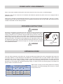
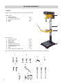
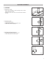
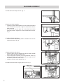
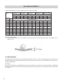
INDUSTRIAL TOOLS
K2532
MAXI PEDESTAL DRILL PRESS
OPERATOR’S MANUAL
BEFORE USE, ENSURE EVERYONE USING THIS MACHINE READS AND UNDERSTANDS
ALL SAFETY AND OPERATING INSTRUCTIONS IN THIS MANUAL .
Serial #............................................
Date of Purchase............................................
TRADEMASTER HEAVY DUTY DRILL PRESS - K2532
IMPORTED & DISTRIBUTED BY
INDUSTRIAL TOOL & MACHINERY
18 BUSINESS ST
YATALA QLD 4207 AUSTRALIA
INDUSTRIAL TOOL
& MACHINERY SALES
07 3287 1114
T
07 3287 1115
F
[email protected]
E
www.industrialtool.com.au
W
SALES
WARRANTY TERMS
In addition to any warranties or conditions implied by applicable Statute or Regulations,
Industrial Tool & Machinery Sales warrants all of it’s products against defective workmanship
and faulty materials for a period of twelve (12) months from the date of purchase, unless
otherwise stated. At our option we will repair or replace, free of charge, any item on the
condition that:
• The complete machine or tool is returned, freight prepaid to ITM or one of it’s authorised
service agents as directed by ITM, and is found to have a material or constructional defect.
• The machine or tool has not been subject to misuse, neglect or damage by accident.
• The fault is not a result of normal “wear and tear”.
• Written permission has been received from ITM prior to commencement of repair.
• Repairs, tampering or modification carried out by unauthorised personnel will void all
warranty.
• Consumable items such as cutting tools, pilot pins, saw blades, grinding wheels etc. are
NOT covered by warranty.
Our goods come with guarantees which cannot be excluded under the Australian Consumer
Law. You are entitled to replacement or refund for a major failure and to compensation for
other reasonably foreseeable loss or damage. You are also entitled to have the goods repaired
or replaced if the goods fail to be of acceptable quality and the failure does not amount to a
major failure.
TABLE OF CONTENTS
Warranty Terms . . . . . . . . . . . . . . . . . . . . . . . . . . . . . . . . . . . . 2
Important Safety Instructions . . . . . . . . . . . . . . . . . . . . . . . . . . . . 3 - 4
Special Safety Rules For Drill Press . . . . . . . . . . . . . . . . . . . . . . . . 4
Power Supply . . . . . . . . . . . . . . . . . . . . . . . . . . . . . . . . . . . . . . . . . . . 5
Grounding Instructions . . . . . . . . . . . . . . . . . . . . . . . . . . . . . . . . . . . 5
Extension Cords . . . . . . . . . . . . . . . . . . . . . . . . . . . . . . . . . . . . . . . . . . 5
Machine Assembly . . . . . . . . . . . . . . . . . . . . . . . . . . . . . . . . . . . . . . . 6 - 10
Assembly Diagram & Parts List . . . . . . . . . . . . . . . . . . . . . . . . . .11 - 12
2
IMPORTANT SAFETY INSTRUCTIONS
WARNING
WHEN USING ELECTRICAL TOOLS, BASIC SAFETY PRECAUTIONS SHOULD ALWAYS BE FOLLOWED TO REDUCE
RISK OF FIRE, ELECTRIC SHOCK AND PERSONAL INJURY .
READ AND SAVE ALL INSTRUCTIONS FOR FUTURE REFERENCE.
1. Keep Work Area Clean
• Cluttered areas and benches increase risk of injuries.
2. Consider Work Area Environment
• Do not expose power tools to rain.
• Do not use power tools in damp or wet locations.
• Keep work area well lit.
• Do not use tool in presence of flammable liquids or gases.
3. Guard Against Electric Shock
• Prevent body contact with grounded surfaces. For example: pipes, radiators, ranges and refrigerator
enclosures.
4. Keep Children Away
• Do not let visitors contact tool or extension cord.
• All visitors should be kept away from work area.
5. Store Idle Tools
• When not in use, tools should be stored in a dry, high and locked-up place, out of reach of children.
6. Do Not Force Tool
• It will do the job better and safer at the rate for which it was intended.
7. Use The Right Tool
• Do not force a small tool or attachment to do the job of a heavy-duty tool.
• Do not use tool for unintended purpose. For example: Do not use a circular saw for cutting tree limbs or logs.
8. Dress Properly
• Do not wear loose clothing or jewellery. They can be caught in moving parts.
• Rubber gloves and non-skid footwear are recommended when working outdoors.
• Wear protective hair covering to contain long hair.
• Always wear safety glasses
• Use face or dust mask if necessary
• Use hearing protection
9. Do Not Abuse Electrical Cord
• Never carry tool by cord or yank it to disconnect from receptacle.
• Keep cord away from heat, oil and sharp edges.
10. Secure Work
• Use clamps or a vise to hold work. It’s safer than using your hand and it frees both hands to operate tool.
11. Do Not Overreach
• Keep proper footing and balance at all times.
3
IMPORTANT SAFETY INSTRUCTIONS
12. Maintain Tools With Care
• Keep tools sharp and clean for better and safer performance.
• Follow instructions for lubricating and changing accessories.
• Inspect tool cords periodically and if damaged, have repaired by authorised service facility.
• Inspect extension cords periodically and replace if damaged.
• Keep handles dry, clean, and free from oil and grease.
13. Disconnect Tools
• Unplug when not in use, before servicing, and when changing accessories, such as cutters.
14. Remove Adjusting Keys And Wrenches
• Form habit of checking to see that keys and adjusting wrenches are removed from tool before turning it on.
15. Avoid Unintentional Starting
• Do not carry a plugged-in tool. Always disconnect from power source before moving.
• Be sure switches are off before connecting to a power source.
16. Outdoor Use Of Extension Cords
• When tool is used outdoors, use only extension cords intended for use outdoors and so marked.
17. Stay Alert
• Watch what you are doing. Use common sense. Do not operate tool when you are tired.
• Do not use when taking medications that may cause drowsiness.
18. Check Damaged Parts
• Before further use of the tool, any damaged parts should be repaired and performance verified prior to
operation.
• Check alignment of moving parts, binding of parts, breakage of parts, mounting, and any other conditions that
may affect its operation. Any part that is damaged should be properly repaired or replaced by an authorised
service centre.
• Do not use this tool if switches do not turn it on and off. Have defective switches replaced by an authorised
service centre.
SPECIAL SAFETY RULES FOR DRILL PRESS
1. Caution: This drill press is intended for use with drill bits. The use of accessories may be hazardous.
2. Correct drilling speeds: Factors which determine the best speed to use in any drill press operation are: Type of
material being worked, size of hole, type of drill or other cutter, and quality of cut desired. The smaller the drill,
the greater the required RPM. In soft materials, the speed should be higher than for hard metals.
3. Drilling in metal: Use clamps to hold the work when drilling in metal. The work should never be held in the bare
hand, the flutes of the drill may seize the work at any time, especially when breaking through the stock. If the
piece is whirled out of the operator’s hand, he may be injured, in any case, the drill will; be broken when the work
strikes the column.
4. The work must be clamped firmly whilst while drilling: Any tilting, twisting, or shifting results not only in a rough
hole, but also increases drill breakage. For flat work, lay the piece on a wooden base and clamp it firmly down
against the table to prevent it from turning. If the piece is of irregular shape and cannot be laid flat on the table,
it should be securely blocked and clamped.
5. The chuck shall be securely fastened to the spindle and so that it can’t be separated from the spindle.
6. Remove the key from the chuck after adjustment.
7. The tool is to be disconnected from the power supply while the motor is being mounted, connected, or reconnected.
8. Secure the tool to the supporting structure if, during normal operation, there is any tendency for the tool to tip
over, slide, or walk on the supporting surface.
9. The set screws of the head frame should be screwed tightly before using this machine.
10. Connect to a supply circuit protected by a circuit breaker or time delay fuse.
11. Fasten base to floor or worktable before using the drill press.
4
POWER SUPPLY REQUIREMENTS
Prior to use check condition of the power cord, which has to be free of any cuts, or similar damages.
Attention!: This unit has a class one of insulation and absolutely requires the power source to be equipped with a
protection circuit.
Power source should be protected with the difference-current circuit cut-out and protected with a 10A fuse - for 230V.
At building sites, power should be supplied from a separation transformer such as Type AVM, with minimum power
of 2000 VA and with second class protection.
GROUNDING INSTRUCTIONS
WARNING
Improperly connecting the grounding wire can result in the risk of electrical shock.
Check with a qualified electrician if you are in doubt as to whether the outlet is
properly grounded. Do not modify the plug provided with tool. Never remove the
grounding prong from the plug. If the cord or plug is damaged, have it repaired
before using. If the plug will not fit the outlet, have a proper outlet installed by a
qualified electrician. The K2532 must be plugged into an appropriate outlet, properly installed and grounded in accordance with all codes and ordinances. The plug
and outlet should look similar to those in Figure A. If in doubt of proper grounding,
call a qualified electrician.
WARNING
Grounding Prong
Outlet Ground
Fig A.
EXTENSION CORDS
Use only 3-wire extension cords that have 3-prong grounding-type plugs and 3-pole receptacles that accept the
tool’s plug. Replace or repair damaged cords. Make sure your extension cord is in good condition. When using an
extension cord, be sure to use one heavy enough to carry the current your product will draw. An under sized cord
will cause a drop in line voltage resulting in loss of power and overheating. See table for the correct size to use
depending on cord length and nameplate amperage rating. If in doubt, use the next heavier gauge. The smaller the
gauge number, the heavier the cord.
VOLTS
240V
MINIMUM GAUGE FOR EXTENSION CORDS
TOTAL LENGTH OF CORD IN METRES
0-15
15-30
30-60
60-90
DRIP LOOP: To help prevent cutting fluids from travelling
along power cord and contacting power source, tie a drip
loop in power cord.
AMPERAGE
0-6
6-10
10-12
12-16
16
14
18
16
14
12
18
16
14
12
16
16
NOT RECOMMENDED
14
12
RECOMMENDED WIRE GAUGE
5
MACHINE ASSEMBLY
I. PARTS
Unpack carton, check your machine to see parts listed below:
1
A. Main Parts:
1. Head assembly
2. Column with flange
3. Arm of table and bracket
4. Table
5. Base
1 pc.
1 pc.
1 set.
1 pc.
1 pc.
4
2
3
B. Accessories:
1. Screw washer nut
2. Bolt & washer
3. Clamp bolt
4. Clamp handle
5. Hexagon socket wrench
6. Height adjustment handle
7. Feed handle knob
8. Drift
9. Chuck, chuck key & taper arbor
2 pcs.
3 pc.
1 pc.
1 pc.
2 pcs.
1 pc.
3 pcs.
1 pc.
1 set.
5
Note: If you find any parts missing or damaged, contact the dealer for exchange or replacement.
1
2
3
5
6
7
6
8
4
9
MACHINE ASSEMBLY
II. ASSEMBLY
1. Assemble the column
• Place column assembly on base and align holes in column
support with holes in base.
• Secure the column with three or four bolts and the washers
provided.
Fig.1
2. Install table bracket
• Take off collar and rack.
• Install table bracket together with rack. Fig. 2.
• Install collar and fix firmly. Fig. 3.
3. Install table handle and clamp bolt.
• Fix handle with attached set screw. Fig. 4.
• Install clamp bolt to fix bracket. Fig. 5.
Fig.2
Fig.3
Fig.4
Fig.5
7
MACHINE ASSEMBLY
4. Install table and clamp with bolt. Fig. 6.
Fig.6
5. Attach the Head Assembly
• Carefully put the head assembly over the column and slide it
onto the column into position. Align the head frame with the
table and base.
• Fix set screws into the right side of the head to lock the
head into position. Tighten the screws with the Allen wrench.
Fig. 7.
Fig.7
6. Install the Feeding Handles
• Screw knob on each feeding handle, install them into the hub
of the pinion shaft. Fig. 8.
Fig.8
7. Attach the Arbor and Chuck
• Insert the arbor into the spindle first. Pull the feeding handle
down to press the arbor inward. Fig. 9.
• Open chuck jaws completely by turning attached chuck key
counter-clockwise to the end. Put a piece of scrap wood on
the table to protect the chuck nose.
• Install the chuck to arbor tightly. Fig. 10.
8. Install knob and screw of upper pulley cover. Fig. 11.
Fig.9
Pulley case
knob & screw
Fig.11
8
Fig.10
MACHINE ASSEMBLY
III. ADJUSTMENT
1. Table Adjustment
• Height Adjustment: To adjust up or down, loosen the clamp
bolt then adjust the table to your desired position by turning
the table bracket handle. Fig. 12.
• Tilting Adjustment: Loosen the table bevel lock bolt with
adjustable wrench. Tilt the table to desired angle and
retighten the bolt. Fig. 13.
• Swing 360°: Loosen the clamp bolt then swing the table to
the appropriate position and retighten the clamp bolt. Fig. 14.
Table Bracket handle
Fig.12
Lock nut
Fig.13
Clamp bolt
Fig.14
2. Feed Depth Adjustment
• Depth control scale sleeve type loosen the clamp bolt and
move it to the desired depth then retighten the clamp bolt.
Fig. 15-1 & 15-2.
Fig.15-1
Fig.15-2
9
MACHINE ASSEMBLY
The proper drill speed for a given drill bit size is as on following table:
Size
Cast Steel
Tool Steel
Cast Iron
Mild Steel
Alum. & Copper
m/min ft/min
m/min ft/min
m/min
ft/min
m/min
ft/min
m/min ft/min
12
40
18
60
24
80
30
100
60
200
Cutting Speed
Diameter
mm
inch
2
1/16
1910
2445
2865
3665
Cutting Speed RPM
3820
4890
4775
6110
9550
12225
3
1/8
1275
1220
1910
1835
2545
2445
3185
3055
6365
6110
5
3/16
765
815
1145
1220
1530
1630
1910
2035
3820
4075
6
1/4
610
610
955
915
1275
1220
1590
1530
3180
3055
8
5/16
480
490
715
735
955
980
1195
1220
2390
2445
10
3/8
380
405
570
610
765
815
955
1020
1910
2035
11
7/16
350
350
520
525
700
700
870
875
1740
1745
13
1/2
300
305
440
460
590
610
735
765
1470
1530
16
5/8
240
245
360
365
480
490
600
610
1200
1220
19
3/4
190
205
285
305
380
405
480
510
955
1020
Belt Tension Adjustment
• For proper belt tension: Use 10 lbs pressure or hand pressure on the belt as shown below. The distance is 1/2”
(13mm) +10%
IV. MAINTENANCE
Frequently blow out any dust that may accumulate inside the motor. A coat of automobile-type wax applied to the
table and column will help to keep surfaces clean. If the power cord is worn or cut, or damaged in any way, have it
replaced immediately.
Lubrication
All of the ball bearings are packaged with grease at the factory. They require no further lubrication. Periodically
lubricate the gear rack and the rack elevation mechanism, the splines (grooves) in the spindle, and the rack (teeth
on the quill).
10
ASSEMBLY DIAGRAM & PARTS LIST
11
ASSEMBLY DIAGRAM & PARTS LIST
12
PARTS #
DESCRIPTION
PARTS #
DESCRIPTION
1
Base
42
Screw
2
Flange
43
Screw
3
Washer
44
Pulley Cover
4
Screw
45
Screw
5
Column
46
Set Screw
6
Rack
47
Motor Pulley
7
Shafting Rod
48
Knob
8
Set screw
49
Ball Bearing
9
Table Bracket
50
V-Belt
10
Clamp Bolt
51
Middle Pulley
11
Table Tilting Label
52
Pivot Bracket
12
Work Table
53
Power Cord
13
Screw
54
Cable Protection
14
Washer
55
Thumb Screw
15
Nut
56
Screw
16
Worm and Worm Gear
57
Wire Fixed Buckle
17
Rack Collar
58
Screw
18
Set Screw
59
Switch
19
Handle Body
60
Nylon Nut
20
Handle Body
61
Spring Cover
21
Knob
62
22
Stop Pin
63
Name Plate
23
Feed Pinion
64
V-Belt
24
Thumb Screw
65
Nut
25
Scale
66
Spindle Pulley
26
Scale Sleeve
67
Retaining Ring
27
Zero Mark
68
Drive Taper
28
Spring Pin
69
Ball Bearing
29
Head
70
Ball Spacer
30
Set Screw
71
Retaining Ring
31
Adjusting Bolt C
72
Retaining Ring
32
Thumb Screw
73
Ball Bearing
33
Mounting Plate
74
Rubber Washer
34
Motor
75
Quill
35
Washer
76
Wedge
36
Nut
77
Ball Bearing
37
Nut
78
Spindle
38
Washer
79
Morse Taper Arbor
39
Shaft Lever
80
Chuck Key
40
Adjusting Bolt B
81
Chuck
41
Washer