1
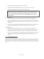
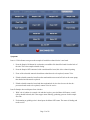
FM – 6 FERROGRAM MAKER USER MANUAL Revision C March 2013 Trico Corporation 1235 Hickory Street Pewaukee, WI 53072 Phone: 262.691.9336 www.tricocorp.com Model:___________________________________ Serial Number:____________________________ Date of Purchase:__________________________ Windows Product Serial Number: ________________________________________ Table of Contents 1. Introduction………………………………………………………………………. 4 1.1 Related Documentation………………………………………………………… 4 2. Packing List and Assembly ……….……………………………………………... 5 2.1 FM-6 Unit Assembly…………………………………………………………... 5 3. Specifications and Operating Parameters………………………………………. 7 3.1 Physical Specifications………………………………………………………... 7 3.2 Power…………………………………………………………………………... 7 3.3 Unit Configuration……………………………………………………………... 7 3.4 Environmental Conditions……………………………………………………... 7 4. FM Nomenclature………………………………………………………………… 8 4.1 Major Components…………………………………………………………….. 8 4.2 Light Indicators.................................................................................................... 10 4.2.1 Station 1 and 2 Array Lights…………………………………………... 10 4.2.2 System Indicators Lights……………………………………………….10 5. Consumables and Accessories…………...………………………………………………. 11 6. Fixer Pump Priming Procedure………………………………………………………… 12 7. Oil Sample Preparation…………………………………………………………... 14 7.1 Fixer Filtered Solvent and Oil…………………………………………………..14 7.2 Dispensers……………………………………………………………………….14 7.2.1 Setting up Dispenser Assembly………………………………………... 15 7.2.2 Using the Pipette Dispenser……………………………………………. 15 7.3 Preparing Oil Sample………………………………………………………....... 16 8. Run FM Procedures……………………………………………………………….17 8.1 Oil Samples for Testing………………………………………………………... 17 8.2 Initiating the FM-6……………………………………………………………... 17 8.3 Shut Down Procedures………………………………………………………… 18 8.4 Operating Procedures…………………………………………………………... 18 8.4.1 Automatic Cycle……………………………………………………….. 18 8.4.2 Semi-Automatic Cycle…………………………………………………. 21 8.4.3 Fixer Cycle……………………………………………………………... 22 8.5 Clean Sample Analysis………………………………………………………… 22 9. Configuration……………………………………………………………………... 23 9.1 Post Sample Delay Cycle Time………………………………………………... 23 9.2 Fixer Dispensing Cycle Time………………………………………………….. 23 10. Tools and About Tab……………………………………………………………... 24 Page 2 of 36 11. Troubleshooting and Maintenance……………………………………………….25 11.1 Troubleshooting……………………………………………………………......25 11.2 Maintenance…………………………………………………………………... 28 11.2.1 Daily Maintenance or as Needed……………………………………… 28 11.2.2 Weekly Maintenance………………………………………………….. 28 11.3 Sample Tube Seal……………………………………………………………. 28 11.4 Over Flow Well…………………………………………………………….....29 11.5 Diagnostics…………………………………………………………………….29 11.5.1 Manual Sensor Checks……………………………………………….. 29 11.5.2 Using the Diagnostic…………………………………………………. 30 11.6 Bubble Level………………………………………………………………….. 32 11.7 Calibration……………………………………………………………………..32 12. Warranty………………………………………………………………………….. 34 Page 3 of 36 1. Introduction The FM-6 Ferrogram Maker is a major component of Trico’s most advanced analytical Ferrograph system. The FM-6 is more versatile, ergonomic and user friendly than its predecessors. Running on a Windows 7 platform allows users to quickly upgrade software to the latest version, interface through the internet, and set up e-mail capabilities. The USB connections can easily set up multiple pieces of lab equipment together, connect to the user lab software or use peripheral devices such as the Ferroscope camera. The provided Ethernet port allows users to network into their current systems. The FM-6 instrument is designed with two independent stations to allow concurrent preparation of two samples. Each station includes a holder to correctly position a sample slide over a magnetic field. The FM-6 working in automatic mode, deposits a prepared fluid sample on the slide at a carefully controlled rate. At the end of this sample deposition, a fixing solution washes the sample slide leaving only wear particles and contaminants on the Ferrogram slide for analysis. Audio and visual signals indicate when the Ferrogram is ready for microscopic evaluation on the Ferroscope. The FM-6 can be operated in automatic, semi-automatic and manual modes. It offers several significant advantages over its predecessor, the Dual Ferrograph, including automatic mode, reduced Ferrogram production time, improved waste handling and fume venting. Configuration and settings can be changed on the fly making it easier to control samples with different viscosities and to tune the unit for increased production. An additional diagnostics feature helps to set-up and troubleshoot the unit. 1.1 – RELATED DOCUMENTATION Trico offers the Wear Particle Atlas (P/N 76-0030) to support predictive maintenance efforts in helping to identify wear particles. This Atlas is an encyclopedia of information exclusively involving wear debris and measuring techniques. The Wear Particle Atlas is available with upgrade software versions. Contact your dealer for further information. The User Manual is adequate for operating and maintaining the FM-6. Page 4 of 36 2. PackingListandAssembly The purpose of this section is to aid the user with the initial assembly procedures required when the FM-6 is first taken out of the shipping container. There are only a few steps that must be carried out. The FM-6 is shipped in a single box which contains the following items: 1 – FM-6 unit 1 – User Manual 1 – Universal AC cord 1 – O-ring Kits 2 – Vial Clips 1 – Fuse 1 – USB Mouse 1 – Waste Bottle 1 – Dust Cover 2.1 – FM-6 UNIT ASSEMBLY To assemble the parts, follow these instructions: 1. Carefully remove the FM-6 unit from the box and place it on a hard level work surface or table to support a load greater than 27 lbs (12 kg). 2. Locate the nameplate on the back panel. Record the serial number on the cover of the User Manual for future reference. 3. Unpack the waste bottle and place the bottle into the waste bay by pressing the top right portion of the door inward and allowing the door to open. Gently pull the waste cap from the bay and thread the bottle onto the cap and tighten. Push the hose coming from the top of the waste bay back into the unit and place the bottle into the cradle. Then close the waste bay door. 4. Place the fixer bottle into the fixer bay located on the right side of the FM-6 by tipping the bottle and placing the tubing into the neck. Then position the bottle with the label facing outward into the fixer bay. NOTE: Not facing the label outward blocks the sensors and will give false indications. 5. Locate the universal AC cord and place the female IEC plug into the male socket on the FM-6. 6. On the bottom right side there is the sample pump vent barb, a 1/8” diameter line can be connected to the barb and run to a vent hood if necessary to vent fumes. 7. Ensure the support feet under the waste and fixer bay are adjusted in the up position. 8. Place the male plug end into appropriate AC electrical outlet. Page 5 of 36 9. Rotate the two adjustable feet located under the front of the unit clockwise or counter-clockwise to level the unit. Two bubble levels are located between the magnet assemblies to indicate when the unit is level. 10. Once the unit has been leveled, lower the two support feet that are located under the waste and fixer bays until they make contact with the top of the countertop. Page 6 of 36 3. SpecificationsandOperatingParameters 3.1 – P HYSICAL SPECIFICATIONS Length (front to back) Width (side to side) Height Weight (instrument) 14.00 in. 12.00 in. 11.00 in. 27 lbs. 33.5 cm 30.4 cm 27.9 cm 12 kg 3.2 – POWER Voltage: Frequency: Amperage: 100-240V AC 50/60 Hz 1A Instrument contains a 1A power fuse located at the power plug inlet. 3.3 – UNIT CONFIGURATUION Operating system: Memory: External USB Ports: Ethernet Connection: Windows 7 16 GB Flash 4 x USB “A” RJ45 cat 5 3.4 – ENVIRONMENTAL CONDITIONS For indoor use on a solid level surface without movement or vibration. Use in a well ventilated area. Room temperature: 50ºF to 85ºF 10ºC to 29ºC Humidity: 50% to 50% non-condensing CAUTION: DO NOT operate the FM-6 with the back panel removed. Unplug the FM-6 from the power supply before removing the back panel for fixer pump adjustments. Check with Trico before removing as this could void the unit warranty. All other repairs must be done at the factory. Page 7 of 36 4. FMNomenclature Figure 4.1 4.1 – MAJOR COMPONENTS This section introduces the user to the major components of the FM-6 Ferrogram Maker. The following subparagraphs discuss the major components, their location, and the nomenclature for each item on the FM-6 Ferrogram Maker (refer to Figure 4.1). 1. LCD Screen: This displays the set-up and operational screens which has several options available besides the calibration menu. 2. Vial Holder: Holds sample vials in place to make a seal with the sample head assembly. To maintain clamping gently squeeze the vial holder prongs together. This part will eventually wear out and is replaceable by unscrewing the two screws holding the clip to the vial holder and replacing the part. 3. Sample Vial: The sample vial contains the mixed lubricant sample and fixer/oil. It is a test tube that holds slightly more than 7 ml. The vial is discarded after each test to avoid contamination. 4. Magnet Assembly: Magnets specifically designed to attract the ferrous particles to the glass substrate that is positioned at a slight angle from the top of the magnet assembly to the bottom where the suction head is located. 5. Sample Head Assembly: The sample head assembly is a multifunctional piece of hardware which holds a sample vial and permits pressure to occur inside so that a constant sample flow rate is carried across the glass substrate during the testing cycle. Page 8 of 36 6. Test Area: The test area is a general term used to describe a grouping of components in or near the particle removal area. It includes: magnet assembly, delivery arm assembly, slide lifter, and vacuum drain (complete descriptions of each of these items are contained in Section 8, Run FM Procedures). 7. Waste Bottle: The waste bottle acts as a reservoir for sample fluid passing over the glass substrate. It is installed on the left side of the FM-6 unit. 8. Fixer Bottle: The fixer bottle is located on the right side of the instrument and provides solvent to both slide making stations. The Fixer Heptane supplied by Trico is filtered to a specified micron level to insure additional particulate is not present on the sample Ferrogram. It is strongly suggested to use the fixer supplied by Trico when running the FM-6 unit. NOTE: Methanol is NOT compatible with the pumps in this unit. 9. Leveling Feet: Two adjustable leveling feet are located on the bottom front of the case and are used to level the magnet assembly. 10. Bubble Levels: There are two bubble level indicators located between station one and station two magnet assemblies. The horizontal level indicates adjustments made in the leveling feet along the X axis while the vertical level indicates adjustments made by the leveling feet in the Z axis. Adjustments should be made to move the center of the bubbles as closes as possible to the black center mark line on the level bubble. 11. Dispensing Arm: The arm raises and lowers the dispensing assembly onto the glass substrate in order to dispense fluid. When in operation, the arm is lowered and the sample tube is inserted into the tube holder at the tip. 12. Model and Serial Number Label: When calling Trico Corporation for repair work on the FM-6, this information will be needed. 13. Power Input Jack: The AC line socket accepts the 3-conductor IEC type AC line cord provided with the FM-6 instrument. 14. Ethernet Network Jack: Ethernet cable can be used to utilize internet/intranet Windows 7 functions. 15. USB Ports: External peripheral devices such as the provided mouse, a keyboard or monitor may be utilized through the USB connections provided as long as they are Windows 7 compatible. 16. On/Off Power Switch: The on/off power switch manually controls the 115/220 VAC input power to the FM-6 instrument. Red indicates ON position, Black indicates OFF position. 17. Back Panel: Taking the back panel off allows the operator to access the fixer pumps and peristaltic tubing. Check with Trico before removing this component to avoid voiding the warranty. Page 9 of 36 4.2 – LIGHT INDICATORS There are five types of light indicators located on the touch screen panel three of these are located in each light array area for each station, two others are system indicators located in the middle of the screen. Each light shows the status of a specific test operation. The lights are described in the following subparagraphs. 4.2.1 - Station 1 and 2 Array Lights Sample Light: When the SAMPLE LED is lit green it indicates a sample vial is present and it is ready to be dispensed onto the glass substrate. If there is no sample light indicated and the AUTO or SEMI buttons are pushed the sample light will blink red indicating no sample vial is present. The sample light turns red when the sample is in the progress of being dispensed and then turns black when empty. Fixer Light: In each station array there is a fixer indicator, when lit yellow the FM-6 is pumping fixer onto the glass substrate. Complete Light: The complete light in each station array turns green when the entire cycle is finished and the Ferrogram is ready for removal. Check the sample substrate to make sure that it is completely dry before removing it from the magnet assembly. 4.2.2 – System Indicators Lights Fixer Light: When the fixer light, located between the station array lights, is lit yellow, it indicates that the fixer bottle is almost empty and needs replacement. When the fixer light is red the bottle is empty and you can no longer run a FM-6 test. Waste Full Light: When a waste bottle is near full the light indicator on the touch screen panel turns yellow to indicate that it is almost time to empty the waste bottle. When full, the light turns red and no more testing will be allowed until the waste bottle is removed and an empty bottle is properly repositioned in the bay. Page 10 of 36 5. ConsumablesandAccessories It will become necessary to reorder a number of consumables to continue testing on the FM-6 unit. This section contains re-ordering information. Many of the test equipment items should not be reused. Contaminated devices can cause inaccurate or incorrect interpretation. PN 73-0060 Sample Vials (Package of 250) – Disposable glass vials hold the oil and fixer and fit properly into the vial holder. PN 75-0020 Pipette Dispenser (Pipettor) – Used to draw oil samples for testing. PN 73-0050 Pipette Tips (Package of 200) – Disposable tips used with the pipettor. PN 74-0016 Fixer-II, Heptane – A filtered solvent used to thin the oil sample for testing and help eliminate breakage of the wetted barrier. The fixer can be used to clean the magnet assemblies. This solvent is non-carcinogenic, but flammable. PN 74-0020 Diluent Oil – Used to assist flow over the substrate and to thin heavily contaminated samples to help prevent particle stacking on the substrate. PN 74-0250 Grease Solvent – An agent used to dissolve grease into a form that can be used with the FM-6 unit. PN 73-0090 Sample Vial Rack – Holds up to 18 sample vials in preparation for testing. PN 74-0060 Glass Substrate – A thin microscope slide specially treated with a Teflon barrier material to keep the sample within the magnet path and guide the sample to the suction head. PN 74-0280 Sample Tubes – Special length of tubing that maintains a seal at the vial head and transfers the sample from the vial to the substrate located on the magnet. NOTE: PN 73-0060, 74-0280 and PN 73-0050 must be discarded after one use in order to eliminate cross-contamination. CAUTION: PN 74-0016 Fixer-II, Heptane and PN 74-0250 Grease Solvent are considered hazardous materials and should be handled with caution and disposed of properly. Consult the Material Safety Data Sheets (MSDS) enclosed with these chemicals for more information. Page 11 of 36 6. FixerPumpPrimingProcedure Each fixer pump is primed and set to the proper flow rates at the factory before shipment. However, fixer in the dispensing lines dissipates quickly and will require the operator to re-prime each line before running Ferrograms on each station when the unit sits for prolonged periods of time. After the FM-6 is set-up and ready to run, test the fixer pumps by pressing and holding the bottom button on right and left side of the control panel marked FIXER. If after 60 seconds, the fixer doesn’t flow follow the procedure below. 1. Press the DIAGNOSTICS tab which allows the user to turn on and off each of the mechanical components of the FM-6. 2. Place a substrate slide onto station one and two. 3. Select the buttons for Fixer Pulse on station one and station two. This will run the fixer pumps without holding the FIXER buttons on the RUN FM tab. 4. Allow fixer to be drawn from the fixer bottle into the pumps and into each line. This may take a few minutes if both fixer lines are dry. 5. If no fixer is dispensed, open the fixer compartment door located on the right side of the machine and remove the fixer bottle. 6. Using the fixer priming bulb, draw some fixer into the bulb from the fixer bottle. 7. Gently pull the fixer line out of the fixer compartment. 8. Insert one of the small tubes from the fixer line into the end of the priming bulb. 9. Elevate the priming bulb and gently squeeze fixer into the line until the fluid comes out one of the lines located at the dispensing arm above the magnet assembly. 10. Turn off the fixer pump in correlation with the fixer line that was primed by pressing either “Fixer 1 off” or “Fixer 2 off” on the DIAGNOSTICS tab screen. 11. Repeat the same procedure to prime the second line. 12. Once primed, insert the fixer line into the fixer bottle and place the bottle into the compartment. 13. Once fixer starts to flow from the dispensing arms onto the slides turn the waste pump on by pressing the Waste ON button in the DIAGNOSTICS tab. Page 12 of 36 14. Run the fixer pumps a few minutes until a constant flow of fixer is dispensing from each arm, purging any bubbles trapped in the lines. 15. Press the Fixer OFF button in the DIAGNOSTICS tab for each station to turn the fixer off. 16. Allow the waste pump to run to remove any excess fixer from the slides; these slides can still be used to collect samples. 17. Ensure that all components are reset by pressing the “All I/O off” button at the bottom of the Diagnostics screen. 18. Select the RUN FM tab on the touch screen menu and follow the FM-6 procedures outlined in this manual. Page 13 of 36 7. OilSamplePreparation 7.1 – FIXER FILTERED SOLVENT AND OIL Fixer (a solvent passed through a 0.45 micron filter) is used to cut the lubricant sample for normal operation. Its function is to loosen wear particles from gels that may form during periods of storage and reduce sample viscosity so that it freely flows through the FM-6 sample tube (PN 74-0280). Trico provides fixer in 400 ml bottles. Refer to Section 5, Consumables and Accessories for details. Filtered oil (mineral oil passed through a 0.45 micron filter) is utilized to dilute the original sample which may contain high concentrations of wear particles that pile up on the Ferrogram, thus masking their true size and shape. For example, 9 ml of filtered oil added to 1 ml of sample produces a 10-to-1 dilution. When filtered oil is used, testing is carried out in the normal manner. Trico offers filtered oil in 400 ml bottles. Refer to Section 5, Consumables and Accessories for details. 7.2 – DISPENSERS Dispensers are mechanical devices that draw fluid from a supply container and deliver measured amounts to a test container. Two types are offered. Dispenser Assembly: The dispenser assembly (refer to Figure 7.1) is used to extract fluid from the 400 ml fixer and filtered oil bottles. It accurately dispenses 1 ml into a test sample vial. Pipette Dispenser: The pipette dispenser (refer to Figure 7.2) is used to extract fluids from the sample bottle to place into a sample vial. It accurately delivers 1 ml of fluid. A disposable pipette tip, which comes in contact with the fluid, fits on the pipette dispenser and is discarded after each test sample to avoid contamination of subsequent samples. Figure 7.1 – Dispenser Assembly Figure 7.2 – Pipette Dispenser Page 14 of 36 7.2.1 – Setting Up the Dispenser Assembly The Dispenser Assembly (PN 75-0010) is used with the 16 oz. (400 ml) bottles of fixer and diluent oil. It accurately dispenses 1 ml of liquid with each stroke. 1. Open the dispenser assembly box and become familiar with the enclosed parts. 2. Thread the appropriate adapter to the top of the fixer or diluent bottle. 3. Measure the dip tube and cut to length so that it touches the bottom of the fixer or diluent bottle. Insert the dip tube in the bottom of the dispenser assembly. 4. Thread the assembly on the fixer or diluent bottle with the adapter in place. 5. Fit the spout to the front of the dispenser assembly and tighten the nut to hold it in place. 6. Prime the dispenser assembly by pumping it several times to remove air bubbles. This step should be done every time the pump sits overnight or longer. 7. The dispenser assembly is now ready to use. 7.2.2 – Using the Pipette Dispenser The PN 75-0020 Pipette Dispenser has been calibrated by Trico to dispense one milliliter of liquid when used according to the following directions. 1. Take the pipettor out of the box and become familiar with it. When pressing the plunger at the top of the pipettor it has two stops. The first occurs when the plunger comes in contact with the plain sleeve. This is the stop used when dispensing one milliliter of fluid. 2. This sleeve and the plunger can be pushed down further until the plunger knob hits the top of the pipettor body. 3. For each new sample use, gently push a new pipette tip PN 73-0050 into the bottom of the pipettor. Using a new tip used with each new oil sample will prevent cross contamination. 4. To draw a sample into the pipette tip, push the plunger all the way to the bottom of the stroke. Put the tip into the liquid and slowly release the plunger. This will bring approximately 1.3 ml of liquid into the tip. 5. To dispense 1.0 ml of liquid, slowly push the plunger to the first stop and hold it there until the liquid stops dripping out of the pipette tip. Some liquid will remain in the pipette tip. This liquid can be discarded or put back into the sample bottle by pushing the plunger down to the next stop. Page 15 of 36 7.3 – PREPARING OIL SAMPLE Gravimetric settling of wear particles in lubricating oil starts immediately after a sample is left standing. To obtain a representative sample from a larger sample, the particles must be evenly dispersed. To make a homogenous mixture, the following procedure is recommended: 1. The oil should be in a clear container to allow for observation of the oil and large contaminants. Make sure the container is two-thirds full to allow for agitation to completely mix the particles into the oil, thus giving the sample a homogenous mixture. 2. Heat the oil to approximately 150°F (65°C). This is according to ASTM standard procedure to keep the particles suspended as long as possible. 3. Remove from the heat source and vigorously shake the bottle. 4. With the pipettor and clean pipette tip, remove 2 ml of oil and dispense into a clean sample vial. 5. Add 1 or 2 ml of fixer to the 2 ml of oil in the sample vial. The viscosity of the oil determines the amount of fixer to add to the oil in the sample vial. For high-viscosity fluids add 2 ml of fixer to reduce the viscosity. This will allow the viscous oil to flow along the glass substrate with ease. For low-viscosity fluids 1 ml of fixer is enough to provide fluid flow on the substrate. It does not matter if 1 or 2 ml of fixer is used, as long as the required 2 ml of oil used for each test. 6. The quicker a sample is tested, the better the results. Allowing the sample to settle in the test vial may cause bunching of particles on the substrate since the majority of material will be collected at the bottom of the vial and deposited on the glass substrate first. To avoid this use the prepared sample as soon as possible or re-mix the sample before testing so that wear particles are properly dispersed. Page 16 of 36 8. RunFMProcedures 8.1 – OIL SAMPLES FOR TESTING Test samples should be obtained from the equipment based on the predictive maintenance program. Specific collection techniques and suggested frequencies are suggested below. Always use approved glass or plastic sample bottles. Never use metal containers. Take samples from the machine while it is operating or no longer than 15 minutes after shut down. Try to take each successive sample while the machine is operating under the same load. Take samples from the same point on the machine every time. Always take samples upstream from a filter. If using a sample valve, make sure stagnant oil is purged from the assembly prior to filling sample bottle. Heat sample to 150ºF (65ºC) prior to testing. Special techniques are required to sample pipes and oil tanks. Please refer to the Trico Wear Atlas for additional information. 8.2 – INITIATING THE FM-6 To initiate the FM-6, follow these basic procedures: 1. Press the on/off switch on the rear of the FM-6 unit to the on position. The sides of the switch will indicate red, when the FM-6 is on. When the FM-6 is on Windows 7 will go through its startup operation and then the FM program will automatically boot. The RUN FM tab of the FM-6 screen will be shown. 2. Verify the FM-6 is level prior to running samples. Make adjustments where appropriate using the leveling feet in front of the unit. Lower the support feet located under the waste and fixer bays for additional support. 3. Place a full fixer bottle into the fixer bay located on the right side of the instrument by pressing the door inward and allowing the door to open. Pull the door away from the magnet closure assembly. When placing fixer bottle into position, gently put the Viton tubing through the neck of the bottle and seat bottle into the cradle. NOTE: Be sure when positioning the fixer bottle that the label is facing outwards to avoid false low level readings indicated by the sensor behind the bottle. 4. Open the waste bay on the left side of the FM-6 and pull the suction cap assembly out. 5. Thread the waste bottle onto the cap and gently push the assembly into the waste bay. Page 17 of 36 6. Check to make sure the waste bottle is in the proper position. Specific sample testing can now be initiated as described in Section 8.4, Operating Procedures. NOTE: Whenever changing the fixer, re-prime the pumping system by pressing the fixer buttons on each station for 60 seconds to clear any air bubbles from the lines. Air bubbles trapped in the fixer tubing can displace material on the glass substrate if not cleared from the system. 8.3 – SHUT DOWN PROCEDURES 1. Close FM-6 program. 2. Go to start menu in lower left corner and go to Windows shutdown command. 3. Allow Windows to completely shut down before turning off power to the unit. 4. Flip power rocker switch from red to black to turn power off. 8.4 – OPERATING PROCEDURES The operating procedures are divided into three groups: automatic cycle, semi-automatic cycle, and fixer cycle. Once a technician is familiar with these procedures, it is only necessary to follow the steps as a refresher. All other information is background and of general interest. 8.4.1 – Automatic Cycle The AUTO button initiates the flow of liquid across the Ferrogram at a controlled rate and automatically switches to a rinse and drying cycle resulting in a completely prepared Ferrogram. 1. Preheat the sample to 150°F (65ºC +/- 5º), in the sample oven prior to testing. 2. Using a pipette dispenser, remove 2 ml of sample lubricant from the sample bottle and add it to a new sample vial. 3. Using the dispenser assembly on the fixer/oil bottle, dispense 1 ml of fixer into the sample vial. Depending on oil viscosity an additional 1 ml of fixer can be added to thin the solution creating 4 ml of solution. 4. Mix solution thoroughly by shaking vigorously with the opening closed or using a vortex mixer. 5. Raise the delivery arm assembly vertically corresponding to the station the sample vial will be positioned in. 6. Insure the wire slide lifter is positioned down against the magnet assembly. 7. Unpack a glass substrate from its protective envelope. 8. Carefully, holding the glass substrate by the edges with the black circle located in the lower left side of the glass substrate, place entry end of the glass substrate on the lip of the magnet assembly Page 18 of 36 with exit end resting on the drain head (exit end is defined by the black dot). The glass substrate should lie at the suction head and the upper end should be lying against the substrate support. NOTE: The black circle viewed on the bottom left-hand side indicates the substrate is in the proper position for sample lubricant to flow down the non-wetting barrier. 9. Lower the delivery arm. 10. Place the sample vial under the sample head assembly according to the station side of the magnet assembly in which the test will run (refer to Figure 8.1). 11. Gently push the sample vial upward, inserting the o-ring seal in the top of the vial while seating the vial tube in the vial clip holder at the bottom to seal it into position. A small amount of diluent oil can be used to lubricate the o-ring seal prior to seating the vial. 12. Place a sample tube through the sample head assembly until it touches the bottom of the sample vial (refer to Figure 8.2). NOTE: Do not leave full sample tubes in opposite station if not running a test. Doing this will close the valves for that station sample and pressure will build in the system. After a period of time this pressure is great enough to force the entire sample out of the sample tube in seconds if a test is initiated. If this situation occurs, remove the sample vial from the vial holder and the valves will open relieving the pressure build up. 13. Push the other end of the sample tube through the end of the delivery arm until the sample tube is about even with the fixer delivery tubing (refer to Figure 8. 3). 14. Using a pen or small round object, gently push the slide against the suction hole in the vacuum drain assembly. If the slide is too long and does not sit flat, replace with a new slide. If the slide is forced in place the slide will shatter (refer to Figure 8.4). 15. Position the delivery arm over the slide. Push the sample tube down until it just touches the slide. Then raise the tubing so that a gap of approximately 1/16 inch (2 mm) exists between the slide surface and sample tube. 16. Press the AUTO cycle button. This action starts initiating pumping of the sample. Once the sample fluid is pumped over the substrate, the FIXER light comes on for eight minutes or the time configured in the CONFIGURATION tab, indicating the fixer is now washing the glass substrate. After pumping, the recommended 4 ml of solvent, the fixer wash pump stops and the vacuum drain continues to run, removing any residual fixer and fumes until the Ferrogram is dry. Page 19 of 36 17. Sample completion is indicated when the COMPLETE cycle green light is on. NOTE: The delay and fixer cycle time can be adjusted on the CONFIGURATION tab. See Section 9, Configuration for details. 18. Check to make sure that the Ferrogram is dry by lifting the delivery arm upward and visually inspecting the Ferrogram for any remaining fixer. NOTE: If the slide is not completely dry, press the FIXER button to turn the vacuum pump on. 19. Position your fingers so that you are holding the Ferrogram by the edges and carefully rotate the top portion upward and then lift away from the vacuum head or use the wire slide lifter by pressing down on the lifting end to raise the glass substrate to be removed. NOTE: Do not move Ferrogram side-to-side near the magnetic field. This may relocate the wear debris and give misleading information. 20. Place Ferrogram into its protective envelope and mark it with the appropriate identification information and/or numbers. 21. Carefully remove the sample tubing and sample vial from the FM-6 and discard. The test is now concluded for automatic cyclic mode. NOTE: If the sample breaks non-wetting barriers, the surface tension of the glass may be too high or the unit is not level. After making sure the unit is level and if the problem continues, the following technique can be used to ensure proper flow within the deposition channel: using a cotton swab soaked in filtered diluent oil, trace the swab down the center of the slide then run the sample as you normally would. This technique modifies the surface tension of the slide in the deposition area, allowing the sample to flow freely. Make sure the cotton swab is clean and free of contaminant particles. Figure 8.1 – Installing Sample Vial Figure 8.2 – Install Sample Tube into Sample Vial Page 20 of 36 Figure 8.3 – Install Sample Tube in Delivery Arm Figure 8.4 – Index Slide on Magnet Assembly 8.4.2 – Semi-Automatic Cycle The SEMI AUTO button initiates the flow of liquid across the Ferrogram at a controlled rate similar to the auto cycle without the rinse cycle automatically coming on. This is purposely done so you may run odd samples with different wash fluids. 1. Refer to Steps 1 through 14 of the Automatic Cycle procedures. 2. Press the SEMI AUTO cycle button. This action initiates pumping action to the sample vial. When the sample vial is empty, the pump continues, removing residual sample fluid for about two minutes. After this period of flushing, the COMPLETE cycle light comes on and a window pops-up prompting the user to change sample vials on the station, indicating the semi-automatic cycle is finished. 3. Remove empty sample vial and replace it with a new sample vial containing 4 ml of the appropriate wash solution. 4. Press the SEMI AUTO cycle button again to initiate the wash cycle. 5. Once the semi-automatic cycle is complete, the Ferrogram is ready for removal. 6. Check to make sure that the Ferrogram is dry by lifting the delivery arm upward and visually inspecting the Ferrogram for any remaining wash fluid. NOTE: If the slide is not completely dry, press the FIXER button to turn the vacuum pump on. 7. Position your fingers so that you are holding the Ferrogram by the edges and carefully rotate the top portion upward and then lift away from the vacuum head or use the wire slide lifter by pressing down on the lifting end to raise the glass substrate to be removed. NOTE: Do not move Ferrogram side-to-side near the magnetic field. This may relocate the wear debris and provide misleading information. Page 21 of 36 8. Place Ferrogram into its protective envelope and mark it with the appropriate identification information and/or numbers. 9. Carefully remove the sample tubing and sample vial from the FM-6 and discard. The test is now complete for semi-automatic cycle mode. 8.4.3 – Fixer Cycle The FIXER button initiates the flow of fixer across the Ferrogram as long as you keep your finger on the button. Once the button is released the flow of fixer stops. NOTE: When pressing the fixer button, the vacuum drain system stays on for 30 seconds in order to ventilate any residual fumes. 8.5 – CLEAN SAMPLE ANALYSIS In some cases, the lubricant sample may be so clean that very few particles fall out on the slide. This generally happens when the Trico Direct Reading Ferrogram DR-6 WPC (Wear Particle Count) results are less than 10. With so few wear particles depositing on the slide, analysis becomes difficult. In this case it is necessary to increase the sample size from 3 ml to 6 ml. Add 2 ml of solvent and run the steps listed in Automatic Cycle or Semi-Automatic Cycle procedures. Page 22 of 36 9. Configuration The CONFIGURATION tab (refer to Figure 9.1) allows the operator to select different settings for each station. The timing options available to you are: fixer dispensing time in the automatic mode and post sample delay time between the end of the sample and the beginning of the fixer dispensing. Settings can be changed on the fly while tests are running by selecting the CONFIGURATION tab and selecting the different settings. However changes do not take effect until the next cycle is started. Pressing the default buttons for each station resets the post sample delay and fixer dispensing time to the default settings. 9.1 – POST SAMPLE DELAY CYCLE TIME The delay cycle time factory setting is two minutes. When the FM-6 is dispensing a sample fluid from a vial (either automatic or semi-automatic mode), the delay is how long the sample vial is pressurized after the last of the sample fluid leaves the vial. This delay ensures that all sample fluid is dispensed before continuing with the next cycle. The delay setting for each side may be set by pressing the up or down arrows to increase or decrease the time. The default for each station is 2 minutes. 9.2 – FIXER DISPENSING CYCLE TIME In the automatic mode, after the post sample delay cycle, the fixer is dispensed automatically at the rate of 0.5 ml/minute. We recommend 4 ml of fixer; therefore the factory setting run time is 8 minutes. When the fixer cycle is complete, the vacuum pump stays on while the Ferrogram is drying to remove any remaining wash fluid and residual fumes. To adjust the time settings for the fixer cycle for each station press the up or down arrows to increase or decrease the time. Figure 9.1 – CONFIGURATION tab screen Page 23 of 36 10. ToolsandAboutTab The TOOLS tab (refer to Figure 10.1) provides operators with additional programs and tools to help identify wear particles and access the User Manual. If the application button is gray and cannot be activated the application is currently not available; but will be in the future. New versions of the FM-6 software can be downloaded off of the Trico website and will update the FM-6 program, offering additional features to the TOOLS tab. Please check periodically with your Trico dealer or Trico website to find the latest software version. The ABOUT tab (refer to Figure 10.2) allows the operator to quickly reference the software version and provides contact information for questions about the unit and its operation and serviceability. Figure 10.1 – Tools tab screen Figure 10.2 – About tab screen Page 24 of 36 11. TroubleshootingandMaintenance 11.1 - TROUBLESHOOTING Table 11.1 is a symptom/probable cause/remedy listing that should be followed when the unit is not operating normally and needs troubleshooting. Service for the FM-6 is available at the location listed below. Users outside the United States should contact their local sale representatives for the address of a service facility located in or near their country. For service in the United States, ship prepaid to: Trico Corporation 1235 Hickory Street Pewaukee, WI 53072 Phone: 800.558.7008 (USA only) or 262.691.9336 It is a good idea to call ahead to make specific arrangements. Trico can inform you of estimated charges after a preliminary check of the equipment is made. Also, refer to the limited warranty page at the end of this manual for additional information. Please return the FM-6 with AC line in its original shipping container if possible. Please do not return the manual, waste bottles, or fixer bottles. CAUTION: Returning waste or fixer bottle could damage the unit because of liquid residue. Page 25 of 36 Table 11.1 Quick Troubleshooting Procedures Symptom Probable Cause Remedy AC line cord not plugged in or damaged. Test cord for correct seating in socket or for shorts. AC line fuse blown. Remove fuse and determine if blown. Various malfunctions. Have unit serviced. Pumps not primed. Hold fixer button until fixer starts to flow or go to Diagnostics tab. No fixer dispensing. Pump not working. Have unit serviced. No suction at drain head. Broken suction line or vacuum pump. Have unit serviced. Suction o-ring missing. Remove magnet cover and replace small o-ring Peristaltic pump tube leaking. Have unit serviced O-ring not sealing sample tubing. Replace o-ring on top of sampling head. Sample head tube seal leaking. Replace main seal (o-ring) under sampling head. Peristaltic pump not turning. Have unit serviced Missing o-ring or seal. Replace seal and o-ring. Waste collection port blocked. Remove magnet from well and unblock waste collection port at bottom. Waste bottle cap not sealing. Program is running but pumps do not operate in modes. Tighten waste bottle cap. Shut down program and restart. On/off power switch is in on position. Unit does not operate. Power is on. Touch panel down not functioning. Sample not dispensing. Oil leaking from magnet area Disconnection light red Page 26 of 36 Shut down system and do cold boot. Auto or Semi Auto mode does not work. Light turns red when button pressed. Sample vial not in place or sensor not reading sample. Fixer below level, indicated as red light on system. Have unit serviced. Insert sample vial with sample, station sample light should be green. Replace with full fixer bottle. Sample vial does not stay in place. Waste bottle full, system lights red. Vial clips bent outwards from normal removal of vial over time. Sample breaks wetted barrier. Glass substrate defective. Empty waste bottle and place back in waste bay. Gently squeeze vial clip prongs together to apply more force to vial clips. Use different glass substrate. Glass substrate not positioned over suction head properly. Reposition glass substrate per procedures. Sample too viscous. Lower sample viscosity by adding 1ml of fixer. Unit not leveled. Check levels and readjust. Assist sample flow. Use cotton swab with diluting oil and run a swipe from the dispensing arm to the suction head. Glass substrate not positioned correctly. Black circle on glass substrate should be in lower left hand corner when positioned on the magnet assembly. Page 27 of 36 11.2 – MAINTENANCE The FM-6, like any other laboratory instrument, must be maintained on a regular basis in order to ensure consistent and accurate operation. Daily cleaning of certain areas of the instrument is necessary to ensure repeatability of results and that no important information is advertently lost due to poor operating habits. The following sections detail daily and weekly maintenance actions and also provide instructions on how to conduct minor repairs. 11.2.1 – Daily Maintenance or as Needed Clean Ferrogram bed area using a paper wipe and a small amount of solvent (Fixer or ACTISol). Clean entire exterior to maintain clean and neat appearance. It is best to use a computer screen wipe that is alcohol or ammonia free to clean the touch screen. Some types of solvent will damage the touch screen, causing yellowing or clouding. 11.2.2 –Weekly Maintenance Clean the magnet assembly cleaning by using a #1 Philips head screwdriver. Gently unscrew the top four screws on the magnet assembly cover. Lift the magnet assembly from the well. Use a paper towel to carefully wipe the excess oil off the magnets and from the bottom of the well. If necessary, place a small amount of fixer solvent on the paper towel and continue to clean. Replace the magnet assembly and the cover assembly, making sure that the cover is snug against the magnet assembly and centered properly. Ensure the two Viton seals remain in the grooves, one around the outside well seal groove and a small oring placed at the front of the well around the suction hole. Failure to position the seals correctly will result in poor suction of fluid off of the substrate during testing. Vial clips located on the lower vial holders may bend outward over time due to normal use of the unit. To adjust, apply force to the vial when in place; gently squeeze the two prongs of the vial clip inward. However, too much pressure or repetitive squeezing over time will cause the prongs to break, these can be replaced by unscrewing the two #1 Philips head screws and mounting a new vial clip provided as a spare with the unit. Additional vial clips can be reordered from Trico (PN 10209). 11.3 – SAMPLE TUBE SEAL Unscrew the plastic thumb screw on top of the sample holder. Using a cotton swab and solvent, gently wipe the interior cavity. This removes any oil that may enter when the sample tube is removed. Any particles that may be generated due to excessive tightening of the thumb screw will also be removed. Examine the small o-ring for damage and replace if worn. A sample tube can help reposition the o-ring by placing the tube through the thumb screw and inserting it through the o-ring. Place the thumb screw back onto the vial holder and tighten down. Remove the sample tube from the thumb screw. Page 28 of 36 11.4 – OVERFLOW WELL In some cases, sample fluid will break the non-wetting barrier and flow off the substrate slide or away from the waste vacuum head assembly. Sometimes, a bad batch of glass substrates results in barrier failures and the only solution is to return the remaining substrates for replacement. If this happens, the fluid passes through the magnets and into the well. This well is emptied automatically each time the waste vacuum is cycled during normal operations. The well can be emptied manually by pressing the FIXER button turning the vacuum pump on. Fluid in the well is then suctioned out for 30 seconds. 11.5 – DIAGNOSTICS The FM-6 runs on the Windows 7 PC platform and is a fully functional minicomputer with limited storage capacity. Trico does not support any Windows operating system. Please contact Microsoft with your Microsoft Windows 7 identification number located on the back cover of the unit for Windows 7 Support. It is highly recommended if connected to the internet that third party anti-virus software is installed. Trico does not warranty any damage caused by third party or malicious software. The DIAGNOSTICS tab is a tool that allows the operator to quickly check the function of all mechanical components with or without needing to call technical support to diagnose issues with the FM-6 unit. Using the diagnostics function, technical support personnel can assist with troubleshooting problems and help to resolve them without further need of shipping the unit for service. The following steps should be taken to go through diagnostic procedures: The indicator light located at the bottom of the DIAGNOSTICS tab indicates if the connection is made to the embedded controller board from the PCB by a green light. If the light remains red then a connectivity problem has occurred. If this happens, shutdown the program by right clicking the mouse and selecting the shutdown command button. Restart the program through the shortcut icon located on the desktop. Check the CONFIGURATION tab disconnection light for a green indication. If the light remains red then shutdown the entire system and reboot. If the disconnected light remains red then contact your local dealer or Trico for service. Follow the step below to conduct the manual sensor checks to ensure that all sensors function properly before using the DIAGNOSTICS tab. An inoperable sensor could cause the unit not to function. 11.5.1 – Manual Sensor Checks Vial Sensors: 1. Place solid object into bottom vial holder for each station. 2. With program running, the sample indicators for each station should turn from black to green. 3. If indicator does not function there is an issue with the sensor, contact Trico. 4. If the indicator changes to green, replace the solid object with a sample vial with 3 ml of water. Page 29 of 36 5. The sample indicator should again change from black to green. 6. If the sample indicator remains black, the sensor value is out of range, contact Trico. 7. If both station sample indicators turn green the vial sensors are good. NOTE: While the program is running and each vial sensor is activated, a small knock sound should be heard. This is the station solenoid closing for sample delivery. When the sensor is cleared a small tick should be heard. This is the solenoid opening again. If the two different noises cannot be heard for each station then go to the DIAGNOSTICS tab screen to check solenoid activation. Waste Bottle Sensors: 1. With the FM-6 program running remove the waste bottle from the left bay compartment. 2. Place a solid object into the path of the lower sensor, the WASTE FULL system indicator in the middle of the RUN FM tab screen should turn yellow, if not there is a sensor issue. Contact Trico for assistance. 3. If the sensor turns yellow then place a solid object in the path of both the lower and upper sensor. The system indicator light for the WASTE FULL should turn red. If not contact Trico. Fixer Bottle Sensors: 1. With the FM-6 program running remove the fixer bottle from the right bay compartment. 2. Place a solid object into the path of the lower sensor. The FIXER indicator in the middle of the RUN FM tab screen should turn yellow, if not there is a sensor issue. Contact Trico for help. 3. If the sensor turns yellow then remove the solid object from the path of both the lower and upper sensor. The system indicator light for the FIXER should turn red. If not contact Trico for assistance. 11.5.2 – Using the Diagnostic Tab Three buttons are located at the bottom of the DIAGNOSTICS tab to turn all mechanical components for each station off or to turn everything off for the system. The user may use these buttons if they are unsure of what components are currently on or off in the diagnostics process and to make sure all components are reset. Page 30 of 36 Symptoms Issue A: Vial indicators turn green when sample is loaded but solenoid noise is not heard. 1. Press the Sample ON button for each station, an audible click should be heard from the back of the unit. This is the sample solenoid closing. 2. Press the Sample OFF button and a tick sound should be heard, this is the solenoid opening. 3. If one of the solenoids cannot be heard then solenoid needs to be replaced, contact Trico. 4. If both solenoids cannot be heard but other mechanicals turn on and off such as the waste pump, then both solenoids must be replaced. 5. If both solenoids cannot be heard and other mechanicals devices also do not work the subprocessor board needs to be replaced, contact Trico for service. Issue B: Sample does not dispense from vial tube. 1. With 3 ml of solution in a sample vial and tube in place, press the Motor ON button, a small ticking should be heard, this is the stepper motor indexing, producing pressure for the sample flow rate. 2. If a humming or grinding noise is heard press the Motor OFF button. The motor is binding and needs service. Page 31 of 36 3. If a ticking sound is heard, press the Sample ON button for the station side having the problem. 4. When the button is pressed a click should be heard and the sample should start dispensing, if no click is heard then the solenoid needs to be serviced. See Issue A for further troubleshooting. 5. If the motor is running and the solenoid functions but no sample is being dispensed then replace the two seals on the vial holder. See Section 11.3 – Sample Tube Seals. 6. If replacing the seals does not solve the dispensing problem then there is an issue with the internal tubing and the unit will need to be serviced. Issue C: Fixer does not dispense. 1. Units that have been sitting for a period of time allow the fixer solution to evaporate from the tubing and need to be re-primed. Press the Fixer Pulse button. This will continuously run the fixer pump. 2. It may take some time for the fixer pump to prime itself, see Section 6, Fixer Pump Priming Procedures for further details and procedures if there is difficulty. 3. Once fixer is present in the fixer pump, a tiny clicking noise should be heard. Depending on the flow rate adjustment this noise could be very soft or very loud depending on the factory flow rate setting. If no noise is heard, this does not mean that the fixer pump is not working it may just mean that the flow rate is dispensing slowly and it may take extra time to purge the fixer tubes. Issue D: Waste pump does not turn on during operation. 1. Select Waste ON, the waste pump should turn on and a loud vibrating noise of the diaphragm pump should be heard. 2. Select Waste OFF to turn the waste pump off. 3. If the waste pump does not function call Trico for servicing. 11.6 – BUBBLE LEVEL The bubble levels located in the middle of the FM-6 are used to level the unit magnets in order to maintain the correct flow across the magnet assembly. Always ensure the magnet level bubbles are leveled by increasing or decreasing the height of the two front adjustable feet by turning them clockwise or counter-clockwise. 11.7 – CALIBRATION The FM-6 does not require calibration. However, there are certain areas that should be checked to ensure that slides are consistent over time and somewhat reproducible among other machines in the field. Shelf Height – The entry end of the Ferrogram is designed to be 0.075 inch above the magnet assembly; the drain end (exit end) should touch the magnet assembly. These dimensions create an angle of approximately 2 degrees. Page 32 of 36 Substrate Length – Substrates are manufactured to 60 mm in total length. Make sure the substrate sits flat and is not bowed upward or misplacement on the entry end shelf. Magnet Strength – The permanent magnets keep their field strength for an indefinite period. If some question arises on whether magnet strength is suspect, it can be tested with a Gauss or Tesla meter. Minimum reading should be 3.0 kilo-Gauss; maximum is 4.0 kilo-Gauss. Sample Flow Rate – Sample flow rate should be constant at 0.5 ml per minute. Sample flow timing at the sensor level is adjustable by increasing or decreasing the time required to pump the sample onto the substrate. This does not affect the actual flow of sample onto the slide. However, more viscous the fluid, the longer it may take to pump onto the substrate. Page 33 of 36 LIMITED WARRANTY Trico warrants to the original purchase only, that these Ferrographic instruments and/or Ferrographic supplies and accessories (the “Product”) are free from defect in material and workmanship and will remedy any such defect according to the terms of this Limited Warranty. Trico will repair (or at its option, replace) at no charge any defective component(s) of Trico’s instruments for twelve (12) months from date of purchase. Trico will repair (or at its option, replace) at no charge any defective component(s) of Trico’s supplies and accessories for ninety (90) days from date of purchase. To make request or claim for service under this Limited Warranty, the original purchaser must return the Product, shipping prepaid, in the original shipping container or equivalent, to Trico, after receiving return authorization from Trico and assuming the risk of loss or damage in transit. This Limited Warranty shall not apply if the Product has been damaged due to abuse, negligence, misuse, misapplication, or accident after the Product has been shipped. Trico does not warranty any damage cause by third party or malicious software. ALL EXPRESS AND IMPLIED WARRATNTIES FOR THIS PRODUCT, INCLUDING THE WARRANTIES OF MERCHANTABILITY AND FITNESS FOR A PARTICULAR PURPOSE, ARE LIMITED IN DURATION TO A PERIOD OF ONE (1) YEAR FROM THE DATE OF PURCHASE FOR INSTRUMENTS AND NINETY (90) DAYS FOR SUPPLIES AND ACCESSORIES, AND NO WARRANTIES, WHETHER EXPRESS OR IMPLIED, WILL APPLY AFTER THESE PERIODS. IF THIS PRODUCT IS NOT IN GOOD WORKING ORDER AS WARRANTED ABOVE, YOUR SOLE REMEDY SHALL BE REPAIR OR REPLACEMENT AS PROVIDED HERE. IN NO EVENT WILL TRICO BE LIABLE TO YOU FOR ANY DAMAGES, INCLUDING ANY LOST PROFITS, LOST SAVINGS OR OTHER INCIDENTAL OR CONSEQUENTIAL DAMAGES ARISING OUT OF THE USE OR INABILITY TO USE SUCH PRODUCT, EVEN IF TRICO HAS BEEN ADVISED OF THE POSSIBLITY OF SUCH DAMAGES, OR FOR ANY CLAIM BY ANY OTHER PARTY. This warranty gives you specific legal rights, and you may also have other rights which may vary from state to state. If any provision of this Limited Warranty is held to be unenforceable for any reason, it shall be modified rather than voided, if possible, in order to achieve the intent of the parties. In such event, all provisions of this Limited Warranty shall be deemed valid and enforceable to the full extent. Trico Corporation 1235 Hickory Street Pewaukee, WI 53072 800.558.7008 or 262.691.9336 www.tricocorp.com Page 34 of 36 Page 35 of 36 Trico Corporation 1235 Hickory Street Pewaukee, WI 53072 800.558.7008 or 262.691.9336 www.tricocorp.com Page 36 of 36