1
IOMASC-2
INSTALLATION, OPERATION, AND MAINTENANCE MANUAL
AND DDC SYSTEM USER MANUAL FOR INDIRECT AND
INDIRECT/DIRECT EVAPORATIVE COOLING UNITS
ATTENTION: READ THIS MANUAL AND ALL LABELS ATTACHED TO THE UNIT CAREFULLY BEFORE
ATTEMPTING TO INSTALL, OPERATE OR SERVICE THESE UNITS! CHECK UNIT DATA PLATE FOR
TYPE OF GAS AND ELECTRICAL SPECIFICATIONS AND MAKE CERTAIN THAT THESE AGREE WITH
THOSE AT POINT OF INSTALLATION. RETAIN FOR FUTURE REFERENCE.
FOR YOUR SAFETY
The use and storage of gasoline or other flammable vapors and liquids in open
containers in the vicinity of this appliance is hazardous.
FOR YOUR SAFETY
If you smell gas:
1. Open Windows
2. Don’t touch electrical switches.
3. Extinguish any open flame.
4. Immediately call your gas supplier.
WARNING: Improper installation, adjustment, alteration, service or maintenance can
cause property damage, injury or death. Read the installation, operating and maintenance
instructions thoroughly before installing or servicing this equipment.
WARNING
Install, operate and maintain unit in accordance with manufacturer's instructions to avoid
exposure to fuel substances or substances from incomplete combustion which can cause
death or serious illness. The state of California has determined that these substances
may cause cancer, birth defects, or other reproductive harm.
INSTALLER'S RESPONSIBILITY
Installer Please Note: This equipment has been tested and inspected. It has been shipped
free from defects from our factory. However, during shipment and installation, problems such as
loose wires, leaks or loose fasteners may occur. It is the installer's responsibility to inspect
and correct any problems that may be found.
4830 Transport Drive, Dallas, TX 75247 Phone: 214-638-6010
www.aztec-server-cooling.com
SECTION I - FOREWARD
As is the case with any fine piece of equipment, care
must be taken to provide the proper attention to the
operation and maintenance details of this machine.
This manual along with the burner IOM (if
applicable) has been prepared in order for you to
become well-acquainted with those details, and in
doing so, you will be able to give your Indirect or
Indirect/Direct Evaporative Cooling System the care
and attention which any piece of equipment needs and
deserves.
It is the customer's and installation personnel
responsibility to determine if the unit is equipped
with all of the safety devices required for the
particular application. Safety considerations
include the accessibility of the unit to non-service
personnel, the provision of electrical lockout
switches, maintenance procedures and automatic
control sequences. Clearly mark all emergency
shutoff devices.
Table of Contents
Section I: Foreword, Table of Contents,
and Important Notice .................................. 2
Section II: General Information .................................... 3
Section III: Installation.................................................. 4
Section IV: Pre-Start Up .............................................. 9
Section V: Unit Start Up ............................................. 10
Section VI: Unit Shut Down........................................ 11
Section VII: Troubleshooting Guide ............................ 12
Section VIII: Maintenance Schedule
and Lubrication Requirements............... 18
Section IX: Replacement Parts .................................. 20
Section X: Aztec DDC System User Manual ............. 21
*IMPORTANCE NOTICE*
Concealed Damage In Transit
Sometimes transit damage is not noticed until the
goods are unpacked. In such cases, notification to
the carrier must be made within fifteen (15) days of
receipt of shipment. In such cases, save the packages
and packing material, then notify the transportation
company at once, and request an inspection. When
the inspector calls, have him make out and leave a
“concealed” bad order report. He is obliged to give one
to you. Insist on it.
Aztec assumes no responsibility for loss or damage
in transit; therefore, you should protect yourself by
following these instructions:
Bill Of Lading
Save your bill of lading. It is a contract, and you will
need it, provided you have to file a loss or damage
claim. Remember, claims are outlawed after nine
months.
Loss In Transit
Before you sign for this shipment, check against the bill
of lading, also the transportation company’s delivery
ticket. Make sure that you get the exact total of articles
listed. Should the delivery ticket show more or less
items than are offered, then the carrier’s agent must
mark the difference on your freight bill before you sign.
Visible Damage In Transit
If anything is damaged, accept the shipment only if
the carrier’s agent places a notation on your freight
bill explaining the nature and extent of damage. Upon
inspection of article, make claim to the delivering
carrier.
Disposition Of Damaged Articles
Never return damaged articles to us. They are the
property of the transportation company when the claim
is filed. They will give you disposition instructions.
Packing
We comply with the packing requirements of the
transportation companies, and your bill of lading
proved that everything was in good condition when
shipped. That bill of lading contract requires them to
deliver in perfect condition.
–2–
SECTION II - GENERAL INFORMATION
A. Purpose
The purpose of this manual along with the burner IOM
(if applicable) is to present a guide for proper installation, maintenance, and operation of the Indirect or Indirect/Direct Evaporative Cooling System, and to supplement, but not to replace, the services of qualified
field service personnel to supervise the initial start-up
and adjustment of the unit. Persons without previous experience with large commercial and industrial
equipment should not attempt the initial adjustment
and checkout procedure which is essential before such
installations may be considered ready for operation.
This manual should be made readily available to all
operating personnel as an aid in troubleshooting and
proper maintenance. Due to the custom nature of this
equipment, not all possibilities are addressed in this
manual. The customer or installer can obtain specific
unit information from the local sales representative or
by contacting the factory directly.
WARNING: Failure to comply with general safety
information may result in extensive property damage, severe personal injury or death.
B. Shipping
Base Indirect or Indirect/Direct Evaporative Cooling units are shipped completely assembled where
shipping limitations or job specifications allow. Any
optional accessories shipped separately are shipped
as assembled sections. Any wired accessories which
have been disassembled for separate shipment require
no additional conduit or wire for field reassembly. All
wire leads will be tagged for ease of reconnection in
the field.
If the unit and/or accessories cannot be installed
immediately, they should be stored in a clean dry
environment. If this is not possible and the unit
must be stored outdoors, it should be protected
from the weather with tarpaulins or plastic
coverings. Do not assume that simply covering a
unit will keep insects, dust and condensation out
of the unit and critical components. Rotate the
fan(s) monthly. Prior to beginning installation of a
unit that has been in storage for weeks or months,
the unit and its components should be closely
inspected.
Shipments are made F.O.B. Dallas, Texas by flatbed truck. The unit is securely strapped, tied, and
blocked to prevent shipping damage. All shipments
are checked by an inspector before they are accepted
by the carrier. Parts that are shipped unmounted are
noted on the bill of lading. These parts, where feasible,
are packaged and shipped with the units. Upon receipt
of shipment, all units should be checked against the
bill of lading to insure all items have been received. All
equipment (and any optional accessories) should be
checked carefully for physical damage in the presence
of the carrier’s representative. If parts are missing or
damage has occurred, a claim should be filed immediately with the carrier.
All Indirect or Indirect/Direct Evaporative Cooling Systems are given a complete operations test and control
circuit checkout before shipment. Copies of the wiring
diagram, piping diagram and bill of material are included with each unit shipped. If correspondence with
the factory is necessary, please provide the unit model
and serial number.
C. Optional Factory Service
Periodic service on any piece of mechanical equipment is necessary for efficient operation. A nationwide
service support network is available to provide quick
and dependable servicing of make-up air, heating,
ventilating, or air handling types of equipment. Factory
start-up service is also available which includes the
presence of a service engineer to supervise the initial
start-up and adjustment of the equipment and provide
instructions for the owner’s maintenance personnel in
proper operations and maintenance. Consult factory
for quotations on start-up or periodic service.
–3–
SECTION III - INSTALLATION
All electrical connections must conform to the current
edition of ANSI/NFPA No. 70 National Electrical Code
and applicable local codes. The following recommendations are not intended to supplant any requirement
of federal, state, or local codes having jurisdiction.
Authorities having jurisdiction should be consulted
before installations are made. Local codes may require
additional safety controls and/or interlocks.
See the specification sheet and submittal drawing
for unit or section weight and to determine proper
orientation for each section.
When unloading sections and/or units or moving
equipment to its final location, exercise care to
avoid distortion. Lift sections and/or units only by
the lifting lugs provided and follow the procedures
as outlined below.
All installations in airplane hangers must be in accordance with current ANSI/NFPA No. 409. All installations in public garages must be in accordance with
current NFPA No. 88A and NFPA No. 88B.
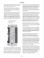
RIGGING AND MOUNTING DATA - INDIRECT OR
INDIRECT/DIRECT EVAPORATIVE COOLING UNITS
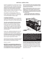
A. Handling the Equipment
As explained previously, the basic unit is designed for
shipping in one piece where shipping limitations allow.
Some optional accessories may require field mounting.
The Indirect or Indirect/Direct Evaporative Cooling
System has been designed for rigging and handling
through the use of special lifting lugs installed on
the top and/or sides of each unit. When unloading
and setting the unit, use the lifting lugs provided as
shown in Drawing #C000737 or move the equipment
on rollers. Hooks, jacks, or chains must not be used
around the casing, main control panel or exterior
mounted controls.
During transit, unloading and setting of the unit, bolts
and nuts may have become loosened. It is recommended that all nuts and set screws be tightened. Turn
fan shaft by hand to make certain that blower does not
rub against blower housing, and that set screws are
tight. If units are not set immediately, cover all openings that might be exposed to the weather.
WARNING: To insure that a proper unit lift is
made, lift unit approximately 24 inches and
verify proper center of gravity lift point. To avoid
dropping of unit, reposition lifting point if unit
is not level. Failure to properly lift unit could
result in death or serious injury or possible
equipment or property-only damage.
Open the cover on the electrical control box located on
the unit. Inspect all wire terminals and wiring terminations to ensure that all connections are tight.
Rotate fans monthly.
IMPORTANT: Lift and install the modules or sections of a unit separately. Flange connections provided between modules or sections are not structural and damage will occur if any attempt is made
to lift modules that have been flanged together.
A spreader bar must be used to span over the unit for
each pair of lifting lugs provided in order to avoid overstressing and damaging the unit’s structure. Position
the unit over the roof curb, platform or mounting pad
and slowly lower into place. Once the unit is in place,
carefully remove lifting cables and spreader bars. Do
not allow the crane’s hook, the spreader bars or lifting
cable to fall on the unit.
–4–
B. Locating the Unit
Prior to locating the unit, authorities having jurisdiction should be consulted before installations are made.
Approval permits should be checked against the unit
received.
The curb assembly may be bolted or welded to either
trusses or roof decking; however, connection to roof
trusses is recommended. The curb is designed to carry
the weight of the unit. Additional support is required for
certain applications.
If in doubt regarding the application of this appliance,
consult the factory.
Placement of the curb is critical in squareness and
leveling. Shims for leveling must be applied to the
curb; application of shims to the unit will tend to
destroy the sealing effect after installation. Make sure
sealing tape is in place before unit is set. Be careful
not to allow gaps where two pieces of sealing tape
meet. A bubble level must be used in the leveling
process. Measure across diagonals to check for
squareness. Allowable tolerance is 1/4" difference
between diagonal measurements. Double-check
approval prints before setting the unit.
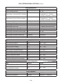
Locate the unit exactly level. Special attention should
be given to the duct, electrical, water, and fuel connection points. The minimum clearance to combustible
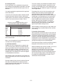
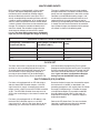
material must be maintained as listed in Table 1.
Table 1
Minimum clearance to combustible material,
also consult local codes and regulations.
Clearances to Combustible Material
Horizontal Units
Front*
36 inches
Rear
6 inches
Right
6 inches
Left
6 inches
Top
12 inches
Floor
6 inches
*Consider control side as front of unit.
**Optimum clearance for coil removal would be equivalent to cabinet width.
Make a visual inspection to insure no damage has occured to the unit during installation.
Upon completion of setting the curb, apply roofing material and flashing as required. Refer to your unit roof
curb drawing.
D. Location of Accessories
Where applicable, standard or optional accessories will
be placed inside the fan section of the unit for shipment,
and must be removed and installed by the mechanical
or electrical contractor. Remotely located discharge or
inlet dampers must be equipped with an end switch and
interlocked to insure maximum design opening before
starting and running circuits may be energized.
Field constructed intake accessories should be properly
designed to minimize the entry of rain and snow.
C. Curb Mounted Units
Outdoor units can be supplied with an optional roof
curb. The curb greatly facilitates installation thereby
reducing installation costs. All connections to the unit:
duct, piping, electrical power and control wiring can
be made through the roof opening. The curb may be
shipped prior to unit shipment. All curbs are shipped
un-assembled from the factory.
Use extreme caution in handling the curb. Proper handling and positioning will assure a water-tight curb unit
installation.
Adequate building relief must be provided, so as to not
over-pressurize the building, when the unit is
operating at its rated capacity. This can be accomplished by taking into account, through standard
engineering methods, the structure’s designed infiltration rate, by providing properly sized relief openings,
by interlocking a powered exhaust system, or by a
combination of these methods.
Re-check approval prints prior to installation. Be sure
that there are no obstructions to ducting and that
proper planning has been exercised in connection of
piping and/or electrical services.
–5–
E. Electrical Connections
Insert a manual shut-off valve in the water supply line
required for the unit’s indirect evaporative section and,
if provided, the direct evaporative section for each unit.
Complete the piping to each section’s 3/4" make-up
water inlet.
WARNING: Open all disconnect switches and
secure in that position before wiring unit.
Failure to do so may result in personal injury or
death from electrical shock.
Proper water quality and environmental conditions will
give you long service life from your cooling tower and
direct evaporative cooling unit. Significant deviation from
“normal” conditions may have a bearing on longevity of
the equipment.
WARNING: Controls must be protected from
water. Do not allow water to drip on the ignition
system.
NOTE: Before installing any wiring, check the unit
rating plate for supply power rating.
“Normal” circulating water chemistry falls within the following limits:
All electrical connections must conform to the current
edition of: ANSI/NFPA No. 70 National Electrical Code
and applicable state and local codes.
•
•
•
Since shipment of unit may require disassembly after
factory check and test, reconnection of some electrical
devices will be required in the field. Connect electrical
wires (supplied in factory furnished conduit) to appropriate terminals. All leads are tagged to facilitate field
connections. See wiring diagram provided with equipment. Complete all wiring to any optional accessories
as shown on unit bill of material and electrical wiring
diagram as required before applying voltage to the unit.
If damper actuators require field wiring, make sure the
gasket and cover are securely mounted and assembly
is watertight.
•
•
•
•
•
•
•
•
Entry location for all field-installed and control wiring is
through the control panel.
If optional disconnect is not furnished with the unit,
the field provided disconnect must be of the proper
size and voltage. Refer to unit rating plate for minimum
circuit ampacity and voltage. The disconnect must be
installed in accordance with Article 430 of the current
edition of ANSI/NFPA No. 70 National Electrical Code.
Check the supply voltage before energizing the unit.
The maximum voltage variation should not exceed
± 10%. Phase voltage unbalance must not exceed 2%.
NOTE: Should any original wire supplied with the
unit have to be replaced, it must be replaced with
wiring material having a temperature rating of at
least 105° C.
pH between 6.5 and 8.0.
Chlorides (expressed as NaCl) below 750 ppm.
Calcium (expressed as CaCO3) below 1200 ppm except in arid climates where the critical level for scale
formation may be much lower.
Sulfates below 5,000 ppm – if calcium exceeds 1200
ppm, sulfates should be limited to 800 ppm (less in
arid climates) to prevent scale formation.
Sulfides below 1 ppm.
Silica (expressed as SiO2) below 150 ppm.
Iron below 3 ppm.
Manganese below 0.1 ppm.
No organic solvents.
No organic nutrients which could promote growth of
algae or slime.
Chlorine (from water treatment) below 1 ppm free
residual for intermittent treatment, below 0.4 ppm free
residual for continuous chloration.
Insert a manual shut-off valve in the drain line from each
unit’s indirect evaporative section and, if provided, the
direct evaporative section’s drain and indirect coil.
Interconnect the lines from each unit’s indirect evaporative section and, if provided, the direct evaporative
section’s drain and indirect coil.
NOTE: The indirect evaporative section and, if
provided, the direct evaporative section of every air
handling unit are provided with an adjustable bleed
valve that is plumbed to each section’s overflow stand
pipe. System drainage for the constant water bleed
from each evaporative section must be provided.
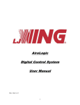
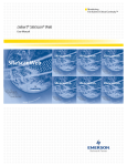
F. Field Piping
Units are provided with a freeze protection and automatic
drain down kit, install the solenoid valves in the following
manner:
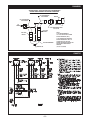
Water Piping
All water piping must be in accordance with project
specifications and the requirements outlined in any
applicable local, state, and national codes. Refer to
drawing #C000751 for typical piping.
1. Install the normally closed and, if provided, the 1/2" or
3/8” normally open water fill line drain solenoid valve in
the water supply line at a point not subject to freezing
temperatures and complete the piping to the make-up
water inlet connection provided on each unit.
–6–
2. Install a manual shut-off valve and the factory provided
normally open solenoid valve in the line from the unit’s
indirect cooling coil and the indirect and direct evaporative section’s sump drain connection.
3. Interconnect the line from the unit’s indirect cooling coil
and the indirect and direct evaporative section’s sump
drain connection to the indirect and direct evaporative section’s overflow connection to form a common
drain line and plumb to an appropriate drain. Install a
P-Trap in the common drain line from the unit’s indirect
evaporative section and, if provided, the direct evaporative section drain and overflow connections. Provide the
P-Trap height as shown in Drawing #C000659B.
4. For colder climates; be sure to provide means to
completely drain the indirect cooling coil and the
indirect and direct evaporative section sumps for
freeze protection.
5. Solenoid valves, in addition to those referenced above
may be provided in some applications. Refer to the
wiring and piping diagrams provided with the unit for
installation information.
Before electrically activating any section of the unit, fill the
indirect evaporative section’s and, if provided, the direct
evaporative section’s sump with water. Check the water level in the sump(s) and verify the setpoint level will not cause
the sump to overflow. See Drawing #C000738 below for
recommended float level adjustment. Adjust the height of
sump water fill and level control valve (if necessary) based
on variations of water supply line pressure. The depth of
the water in the sump should be 1/2" below the top of the
sump’s overflow stand pipe.
For remote cooling towers, supplied either by Aztec or
others, plumb the supply and return lines from the cooling tower to the coil inlet and outlet connections provided on the indirect cooling coil in each Aztec unit.
Building Pressure Transducer Piping (PT-13)
Pipe the high side to a location inside the building that
will not be affected by air movement. Pipe the low side
to the atmosphere, positioned so it will not be affected
by the wind and not exposed to the elements. Be sure
that all tubing is clean and clear of any debris before
installing tubes on the transducer.
G. Duct Connection
Install duct work with adequate flexible connections
to isolate vibration from the duct work. All duct work
should have taped or caulked seams. Duct work
should be properly sized so as not to inhibit airflow.
This information should be cross-checked with the
position of support beams and stand pipes to insure
that clearance dimensions coincide with those of the
unit.
H. Field Wiring and Remote Control Installation
1. Connect the power lines to the line side of the main
disconnect switch.
2. Mount and wire remote control panel, thermostats,
temperature sensors, and any other field installed controls as indicated on the unit control wiring diagram.
3. Connect the wires to the appropriate field wiring
terminals as indicated on the unit control wiring diagram.
4. Field wiring shall have a temperature rating of at
least 105°C. The minimum size of the supply cable
circuit shall be sufficient for the maximum ampacity
of the unit.
I. Locating Temperature Controls
The room or outdoor sensors should be mounted
where they will not be subjected to direct impact of
the heated air or radiant heat from the sun. The side
of building columns away from the heater or interior
walls are usually the location best suited for mounting
thermostats.
Controls with outdoor sensors require that the outdoor
sensor be shielded from direct radiation from the sun. Unit
mounted sensors are factory located and mounted.
–7–
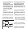
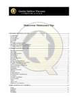
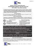
C000659B
SUGGESTED P-TRAP DESIGN FOR CONDENSATE
DRAIN PANS UNDER A NEGATIVE PRESSURE
90° LONG RADIUS
PVC ELBOW
NIPPLE
90° LONG RADIUS
PVC ELBOW
K
TO
DRAIN
DRAIN PAN
PVC ADAPTER FITTING
FPT x SLIP
PVC PIPE
NIPPLE
PVC PIPE
NIPPLE
H
PVC RETURN BEND
DRAIN PLUG
NOTE:
'H' TO BE A MINIMUM OF
1/2" PLUS THE TOTAL SYSTEM
STATIC PRESSURE ("W.C.).
'K' TO EXCEED THE NEGATIVE
STATIC PRESSURE IN "W.C. OF
THE SECTION OF THE UNIT
WHERE THE DRAIN IS INSTALLED
AND DOUBLE WHEN SPACE
PERMITS.
(10/30/09 C000659B)
C000751
–8–
SECTION IV - PRE START-UP
Do not attempt start-up without completely reading
and understanding this manual, along with the
Burner IOM (if applicable).
Pre Start-Up
The owners representative or equipment operator
should be present during start-up to receive instructions
on care and adjustments of the equipment.
All equipment has been factory tested, adjusted, metered
and inspected to meet conditions set at the time the
order was placed. Only minimal adjustments should be
required. All information in this service manual is typical.
All products are semi-custom and changes may occur.
CAUTION: Line side of disconnect may be energized.
Follow proper “lockout/tagout” procedures.
NOTE: All servicing and adjustments of the Indirect
or Indirect/Direct Evaporative Cooling unit should
be performed by a qualified service engineer.
Perform a visual inspection, internally and externally, to
make sure no damage has occurred, that unit is level,
and that everything is secure. This inspection is very
important and should be completed with greatest care
given to detail. A good pre-start inspection will insure
against possible unit damage on start-up and will save
valuable analysis time.
1. Check that the physical condition of the unit
exterior is acceptable.
2. Check that the insulation inside of unit is properly
secured.
3. Remove all shipping blocks, brackets and bolts
from supply fan base with optional isolation base.
4. Check all terminals for loose connections and
inspect all wiring terminations to insure that all
crimped connections are tight.
5. Check set screws on all fans for tightness.
6. Check voltage supplied to disconnect switch; the
maximum voltage variation should not exceed ± 10%.
Phase voltage unbalance must not exceed 2%.
7. Check thermostat(s) for normal operation.
8. Check to ensure all manual reset safety devices
have been reset and limits are in the normal
operating position.
9. Check that system duct work is installed and free
from obstructions.
10. Check that fans turn free in housing.
11. Check that the area in and around the unit is clear
of debris or containers of flammable liquids.
12. Check that all piping connections, particularly
unions, are tight and installed correctly.
13. Check that all accessories requiring field wiring
have been properly installed and wired.
14. Check that filters, filter stops, accessories and ship
loose items are installed correctly.
15. Motor overload relay setting (if applicable) should
match the motor’s nameplate full load amperage.
16. Check that dampers and linkages are free to move,
and that linkages are tight.
17. Do not run the pump without water in the sump of
the indirect evaporative section cooling tower and,
if provided, the direct evaporative cooling section.
18. All float and liquid levels and bleed off rate are preset at the factory during final equipment testing and
quality control inspection. However, these settings
should be verified at the job site.
19. Depending on local water pressure, a pressure
regulating valve may be required to stabilize the
make-up water flow and the operation of the water
fill and level control valve in the unit’s indirect
evaporative section and, if provided, the direct
evaporative section.
This equipment has been tested prior to shipment.
However, during transit control setpoints can change,
and wiring can come loose. Do not assume controls
are defective until all associated setpoints and wiring
are checked.
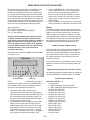
If you do not have the optional BACview 6 (KP-01)
keypad display it will be difficult to troubleshoot
any alarm that may occur on the unit. To reset most
alarms on the I/O FLEX 6126 Controller (UC-01)
without a BACview 6 keypad display, simply turn
the power off and back on at the unit disconnect.
If you have a BACview 6 keypad display the alarm
can be reset remotely or at the I/O FLEX 6126
Controller.
Suggested Tools and Instruments
Volt/Ohm Meter
Thermometer
Tachometer
Ammeter
Manometer (0-10" W.C.)
Microammeter
Standard Hand Tools
D.C. Volt Meter
Refrigeration Gauges (if applicable) BACview 6
–9–
SECTION V - UNIT START-UP
To also enable the fans go to “Unit Modes” and enter
[AUTO], this mode has four different functions that
control the fans and unit operation. They are a Time
Clock, Heating and Cooling Night Setbacks, and signal
from an external source to an auxiliary digital input.
Before attempting to start the unit read and understand the sequence of operations and electrical
schematic, and the Burner IOM (if applicable).
WARNING: During installation, testing,
servicing and troubleshooting of this product,
it may be necessary to work with live electrical
components. Have a qualified licensed
electrician or other individual who has been
properly trained in handling live electrical
components to perform these tasks. Failure to
follow all electrical safety precautions when
exposed to live electrical components could
result in death or serious injury.
To disable the fans go to “Unit Modes” and enter [OFF].
NOTE: A BACview or PC is required to change Unit
Modes.
If power supply meets requirements, turn main
disconnect switch on and enable fans. Damper
opens (if applicable). Blower fan turns on.
Make sure all doors and service panels have been
closed or replaced.
Disable the fans. Check supply blower for proper
rotation.
Check the indirect evaporative section’s and, if provided, the direct evaporative section’s sump low water
level recirculating pump shutoff switch. The low level
switch contact will be normally closed when the sump
is filled with water. As this switch is not field repairable,
replace if found defective.
NOTE: To change rotation of the cooling fan motor
controlled by motor starter, simply interchange
any two (2) of the line leads of the motor starter for
three (3) phase motors. On single phase motors
refer to motor nameplate. To change the rotation
of any three phase motor controlled by a Variable
Frequency Drive (VFD), interchange any two (2) of
the load leads of the VFD.
Turn main disconnect switch off. Check the incoming line
voltage to match unit rating plate rating. If voltage is over
±10% of nameplate rating or phase voltage unbalance is
over 2%, notify contractor or power company.
Enable the fans. Check for proper blower rpm. Check
that all motor amp draws do not exceed rating plate
ratings and overloads are set to motor rating plate amps.
Fans Are Enabled And Disabled By The Following:
MRT Expert or MDT Expert With A BACview (KP-01):
To enable the fans go to “Unit Modes” and enter
[MANUAL], this mode will enable the fans.
– 10 –
Cooling is Enabled By The Following:
MRT Expert or MDT Expert With A BACview (KP-01):
To enable the cooling, scroll through the “Setpoints”
menu in the BACview and enter the desired room
Cooling Occupied and Unoccupied Setpoints.
If the system’s airflow and static pressure are in
accordance with the project specifications, check
for water carryover from the direct evaporative
section’s cooling media, if applicable. If carryover is
observed; close, in small increments, the water flow
balancing valve provided in the direct evaporative
section’s recirculating pump riser until water carry
over is eliminated. The leaving air side of the direct
evaporative media should be damp from top to bottom.
NOTE: If adjustment is required, allow sufficient
time to lapse between each, small incremental
adjustment to the water flow balancing valve to
permit stabilization of the evaporative media to
the new water flow rate before making another
adjustment.
The evaporative media may foam for a period following
initial startup. Leave the water bleed off valve fully
open until the foaming ceases. The water bleed off
valve can then be re-adjusted to approximately 3 – 6%
of the evaporative media’s water recirculation rate. The
actual amount of bleed off required is dependent on
the quality of water used and the rate of evaporation.
As climate conditions change, the rate of evaporation
may increase, thereby requiring an increase in the
bleed off rate. It is recommended that the bleed
off rate be set for the condition of maximum water
evaporation. An indication of insufficient bleed off is a
uniform buildup of minerals on the entering air face of
the evaporative media. If this condition is observed,
increase the rate of bleed off until the mineral deposits
dissipate. Repeated drying of the cooling media will
also cause the rapid buildup of insoluble deposits.
Cooling Tower Setup: The water flow for cooling tower
has been factory set and should require only minimal
adjustments in the field. Use same steps for adjusting
water flow, bleed-off rate, and initial foaming as listed
above for direct evaporative section. The water flow over
the cooling tower media is intended to be much higher
flow rate than the direct evaporative media. It is common
to have water carryover off of the media although the
carryover is normally confined within the cooling tower
section. If adjustment is deemed necessary; there are
ball valves located in the inlet plenum to adjust water flow.
Make small adjustments and make sure all of the inlet
filters are in place and access panel is closed while unit
stabilizes with each new setting.
Check all dampers for proper operation, and that the
linkage does not bind and also see “Sequence of Operation” for damper control modes.
Disable the fans.
Safety Controls Check All
Firestats – These limit controls are not adjustable and
are checked at the factory. Reset the red button(s) to
be sure they are ready for operation. Contact factory if
these switches fail to reset.
SECTION VI - UNIT SHUTDOWN
A. Extended Shutdown —
1. Disable the cooling for 30 seconds, then disable
the fan.
2. Open the main electrical disconnect switch.
3. If the unit is to remain idle for an extended period,
the blower and motor shafts should be rotated by
hand to spread the grease over the bearings.
4. Drain sump(s) and shut-off all water valves.
B. Emergency Shutdown ONLY —
1. Open the main electrical disconnect switch.
– 11 –
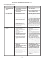
SECTION VII - TROUBLESHOOTING GUIDE
The following is a simplified list of possible problems
and typical causes and remedies. However, it does not
cover all possibilities, and is intended as a guide only.
You might also need to reference the Burner IOM if
applicable.
WARNING: Many of the steps listed on the
following pages require electrical cabinet and
blower access while the unit is powered. High
voltage and moving parts are present, and
these steps should be performed by qualified
service personnel. If any of the controls requiring manual reset were at fault this is an indication of a problem with the system that should
be investigated.
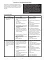
Fan and Cooling Mode
Symptom
Cause
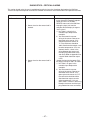
A. Supply air fan or cooling
tower exhaust fan does
not operate.
1. Low or no voltage.
2. Circuit breaker open or fuse(s)
blown.
3. Customer interlock not closed or
connected.
4. Fan is disabled.
5. Field installed controls open.
6. Freeze protection (Low Discharge
Temperature) tripped.
7. BO-1 on UC-01 not energized (if
applicable).
8. BO-4 on UC-01 not energized.
9. Damper motor not operating, it’s
end switch is not making, or the
damper is binding.
Remedy
1. Check power source
2. Check and replace.
3. Close or connect customer interlock.
4. Enable the fan.
5. Check field installed controls for
proper settings.
6. See sequence of operations.
7. See sequence of operations.
8. See sequence of operations.
9. Check for power at damper motor
and that end switch has been wired
correctly to the N.O. (normally
open) contact. Check that the linkage is clear and not binding.
10. Push reset button and check amps.
10. Overload Protection on motor VFD
and /or starter tripped.
11. Check and/or replace.
11. Motor bearings seized.
12. Motor may be burned or incorrectly 12. Turn off power and check motor
and wiring.
wired.
13. Check motor amp draw.
13. Motor overheating.
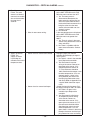
B. Inlet air damper or Return
air/Outside air dampers
operation not functioning
properly (see sequence
of operation for damper
control).
1. Damper motor and/or end switch
not wired correctly or defective.
2. Dampers binding and/or loose.
3. Building Pressure Transducer
(PT-13).
4. Building Pressure Transducer
(PT-13).
5. Building Pressure Transducer
(PT-13).
6. Unit Control Module (UC-01)
defective.
7. Unit Control Module (UC-01) not
wired correctly.
8. Two position switch defective.
9. Damper motor defective.
– 12 –
1. Check wiring and/or replace end
switch.
2. Check and/or replace.
3. Check and/or replace components.
See section on troubleshooting
PT-13.
4. Check wiring.
5. Install correctly. See section on
troubleshooting PT-13 and manufacturer’s cut sheet.
6. Check and/or replace. Contact Factory.
7. Check wiring.
8. Check and/or replace.
9. Check and/or replace.
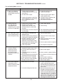
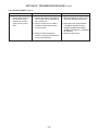
SECTION VII - TROUBLESHOOTING GUIDE continued
Fan and Cooling Mode continued
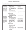
Symptom
C. There is no voltage at
cooling relays (RE-34)
and/or (RE-33) and fan is
enabled.
Cause
1. Cooling mode is disabled.
2. Variable Frequency Drive (FD-01)
not running.
3. Air flow switch is open.
4. Cooling Changeover and/or Economizer Setpoints not set correctly.
5. BO-2 and/or BO-3 are not
energized.
D. Cooling relays (RE34) and/or (RE-33)
are energized and
condensing unit or chiller
are not on (if applicable).
E. Unit’s discharge air flow
rate has decreased or is
below nameplate rating.
Remedy
1. Enable the cooling mode.
2. Check VFD for faults.
3. Check for proper airflow. Adjust
and/or replace switch.
4. Change to correct setpoints. See
sequence of operation.
5. See sequence of operation.
1. Cooling relays (RE-34) and/or
(RE-33) are not closed.
2. Cooling relays (RE-34) and/or
(RE-33) contacts are not wired
correctly.
3. Compressors or chiller water pump
is not running.
1. Check and/or replace.
1. Unit’s supply air inlet filters are
blocked or dirty.
2. System’s external static pressure has
increased or is higher than specified.
3. Building’s exhaust fans are not
operating or building’s relief
openings are not properly sized.
4. Direct evaporative cooling media is
obstructed, dirty, or damaged.
5. VFD ramped down.
1. Clean or replace filters.
F. Recirculating pump
in direct or indirect
evaporative section
does not operate or
the volume of water
being recirculated is not
sufficient.
1. Water level in indirect or direct
evaporative section sump is low.
2. Low sump water level switch is
defective.
3. Customer interlock not closed or
connected.
4. Recirculating pump may be internally
grounded or have heat damage.
5. Pump basket screen is blocked.
6. BO-2 and/or BO-3 not energized.
7. Multiplex resistors are burnt.
G. White mineral deposits
collecting on face of
media in indirect or direct
evaporative section.
1. Water bleed rate is too low.
2. Low recirculating water flow rate.
– 13 –
2. Correct wiring.
3. See Troubleshooting Guide provided
with condensing section or chiller.
2. Correct or contact factory representative.
3. Power up exhaust fans or correct
relief opening size.
4. Clean or replace media as required.
5. See sequence of operation.
1. Fill to proper level.
2. Check and/or replace.
3. Close or connect customer interlock.
4. Turn off power and check pump and
wiring.
5. Clean screen if necessary.
6. See sequence of operation.
7. Check and/or replace.
1. Increase water bleed rate by opening the adjustable bleed valve
provided. Minimum bleed off rate is
3-6% of the total water flow being
recirculated.
2. Open the water flow balancing valve
provided in the direct evaporative
section’s recirculating pump riser. The
media is essentially self-cleaning with
a water flow rate of 1.5 – 2 GPM per
square foot of media pad top area. If
water flow is increased, be sure to
check again for water carry over.
SECTION VII - TROUBLESHOOTING GUIDE continued
Fan and Cooling Mode continued
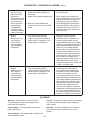
Symptom
H. Uneven water distribution
over evaporative media
surface.
I. Water being carried
over from the direct
evaporative section.
Cause
Remedy
1. Evaporative media and/or media
water distribution pad damaged or
partially blocked.
2. Media water distribution header or
orifices plugged.
1. Remove media and distribution pad.
Clean and/or replace.
1. Localized media face velocity
exceeding 500 FPM.
1a. Inlet air filters are partially obstructed
– Clean or replace filters as required.
1b. Inlet face of media is partially obstructed – Clean or replace evaporative media as required.
2. Check both faces of evaporative media for damage. Replace as required.
3. Adjust water flow rate to evaporative
media until carryover stops by slowing closing the water flow balancing
valve in the recirculating pump’s riser.
4. Decrease air flow through air handler.
2. Evaporative media is damaged.
3. Too much recirculating water.
4. Average media face velocity
exceeds 500 FPM.
5. Uneven water distribution over
evaporative media.
J. Cooling not functioning
properly.
2. Remove media water distribution pad
and clean header and orifices.
5. Clean evaporative media and/or water
distribution header and/or orifices.
1. Check wiring and/or replace bad
components.
2. Adjust setpoints on BACview or
with PC.
3. Abnormally high wet bulb temperatures will decrease performance.
4. Clean and/or replace dirty or damaged
air filters. Check evaporative media for
damage on entering and leaving air
surfaces. Replace if necessary.
5. Open the water flow balancing
5. Incorrect water flow over direct
valve provided in the direct evaposection’s evaporative cooling
rative section’s recirculating pump
media.
riser. The recommended flow rate
is 1.5 – 2 GPM per square foot of
media pad top area. If water flow
is increased, be sure to check
again for water carry over.
6. Building exhaust air relief fan(s) are 6. Check power source. Close or connect interlock to operate fan(s).
not operating.
7. Open for proper relief air flow. Check
7. Ventilation openings are closed or
job specifications for proper sizing.
not properly sized.
8. Check and clean evaporative me8. Media pads are not uniformly wet.
dia, water distribution pad, water
distribution header and orifices.
9. Check pump and piping from tower
9. Water flow rate from cooling tower
to indirect cooling coil for blockage.
pump has decreased.
10. Check media in cooling tower for
10. Water temperature from cooling
damage and also check water recirtower has increased.
culation rate.
1. UC-01 and/or relays not wired
correctly or defective.
2. Setpoint is lower than design
conditions.
3. Check outside wet bulb
temperature.
4. Non uniform air flow across the
face of the evaporative media in
the direct evaporative section.
– 14 –
SECTION VII - TROUBLESHOOTING GUIDE continued
Fan and Cooling Mode continued
Symptom
Cause
Remedy
K. Excess water flow from
the indirect or direct
evaporative section’s
sump into the system
drain.
1. Check if adjustable water bleed off
valve is open too far and bleed off
rate is excessive.
2. Verify that water level in indirect
and direct evaporative section’s
sump is correct.
1. Minimum bleed off rate is 3-6% of the
total water flow being recirculated.
3. Indirect or direct evaporative
section’s sump water fill and level
control valve defective.
– 15 –
2. Water level in the sump should be
1/2" below the top of the sump’s
overflow standpipe. See drawing
#C000738 (in Section III - Installation)
for reference.
3. Repair or replace valve.
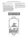
SECTION VII - TROUBLESHOOTING GUIDE continued
To Calibrate the Building Pressure Transducer
(PT-13)
1. Remove the tubes at the Low and High pressure
fittings.
2. The voltage at –COM and OUT should be 2.5 VDC.
If not, adjust Z (do not adjust S).
3. Make sure the Low and High fittings are clean
and clear (do not insert any sharp objects into
the pressure fittings). Make sure the tubing is
also clean, clear of any debris and then reinstall
the tubes on the transducer. It is very important
that the High tube be placed inside the building,
and positioned so that air movement does not
affect it. The Low side should be to atmosphere,
and positioned so it is not exposed to the
weather.
4. With the use of a BACview 6 (KP-01) place the
unit in the Building Pressure mode. (See the DDC
Control System User Manual).
5. The voltage at –COM and OUT will vary between
0 to 5 VDC. 0 VDC means the building is in a
negative pressure and should open the Outside Air
and close the Return Air damper. 5 VDC means the
building is in a positive pressure and should open
the Return Air Damper and close the Outside Air
Damper.
PT-13
SETRA P/N
MESTEX P/N
RANGE
26510R1WBABT1C
68.0330.69
± .1 IN WC
– 16 –
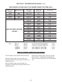
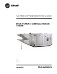
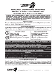
SECTION VII - TROUBLESHOOTING GUIDE continued
MULTIPLEXED VOLTAGE CHART (FOR INDIRECT/DIRECT SYSTEMS ONLY)
RESISTOR
VALUE
RESISTOR ID
1000
2000
4020
8060
RS1
RS2
RS3
RS4
MULTIPLEXED VOLTAGE
VALUES
IN-3
SW-11
SW-10
JUMPER
JUMPER
SWITCH
CLOSED
OHMS IN
CIRCUIT
VOLTS DC
RS1,2,3,4
RS2,3,4
RS1,3,4
RS3,4
RS1,2,4
RS2,4
RS1,4
RS4
RS1,2,3
RS2,3
RS1,3
RS3
RS1,2
RS2
RS1
NONE
UNPLUGGED
0
1000
2000
3000
4020
5020
6020
7020
8060
9060
10060
11060
12080
13080
14080
15080
NA
0
0.83
1.42
1.87
2.22
2.5
2.72
2.91
3.07
3.21
3.33
3.43
3.53
3.61
3.67
3.74
4.98
RS-04
RS-03
RS-02
RS-01
CLG STG 2 FLOAT SWITCH
CLG STG 1 FLOAT SWITCH
NOT USED AT THIS TIME
NOT USED AT THIS TIME
= 2.91
= 3.43
= 3.61
= 3.67
CHECK ALL TERMINAL CONNECTIONS FOR TIGHTNESS
The DC voltage is to be checked at the UC-01 board.
When the cooling stage 1 float switch (SW-10) is
energized, the contacts will close and the VDC at IN-3
& GND will be 3.43.
When both the cooling stage 1 and 2 float switches
(SW-10 & SW-11, respectively) are energized, the
contacts will close and the VDC at IN-3 & GND will be
1.87.
When the cooling stage 2 float switch (SW-11) is
energized, the contacts will close and the VDC at IN-3
& GND will be 2.91.
– 17 –
SECTION VIII - MAINTENANCE SCHEDULE AND LUBRICATION REQUIREMENTS
WARNING: Failure to comply with the general
safety information may result in extensive
property damage, severe personal injury or
death.
WARNING: DO NOT OPERATE THE SUPPLY FAN
OR COOLING TOWER FAN IN THE AIR HANDLER’S
INDIRECT EVAPORATIVE SECTION DURING ANY
CLEANING OF THE UNIT’S EVAPORATIVE MEDIA.
Periodic maintenance is essential to the efficient
operation and extended service life of this equipment.
Failure to provide maintenance as recommended may
void the equipment warranty.
A. Maintenance Schedule
1. Daily
a. Check gauges, monitors, instruments and equipment
settings.
2. Monthly
a. Check all set screens on fan and motor assemblies.
b. Check all valves, piping and connections for leaks.
c. Inspect filters and pump screens. Clean or replace as
necessary.
d. Check all dampers, damper actuators and linkages.
Adjust, lubricate and tighten if necessary.
e. Ensure that there are no obstructions blocking the air
supply or discharge to the unit.
f. Inspect the area and make sure that no combustible
or hazardous material has been stored within the
clearances shown on the unit nameplate.
g. Check and clear all air sensing tubes and fittings.
CAUTION: To prevent damage to the unit,
remove tubes from switches and transducers
before using compressed air to blow through
tubing.
3. Quarterly
a. Complete the monthly maintenance schedule.
b. Check voltages and amp draw on main fan motor.
c. Check the operation of all safety controls individually.
d. Check that the battery in (UC-01) has 3 VDC. Do
not remove or replace battery with the power
turned off to the control.
e. Inspect all evaporative media and coil(s). Clean if
necessary.
f. Inspect all orifices in water distribution system. Clean
if necessary.
g. Flush sediment and debris from Cooling Tower
and Direct Evaporative Cooling Section sump(s).
4. Off Season or Yearly
a. Complete the monthly and quarterly maintenance
schedule.
b. Inspect all fan wheels and props. Clean if necessary.
c. Check that all fan wheels and props are securely set
on the motor shaft.
d. Inspect all electrical components, connections and
terminals. Clean and tighten where necessary.
e. Lubricate fan motor(s) as directed by motor manufacturer.
f. Inspect fan motor(s) wiring for loose connections.
g. Lightly oil all door latches.
h. Check that cabinet is weathertight, replace door gaskets and recaulk as necessary.
CAUTION: The evaporative media has a definite
polarity and must be installed correctly to give
trouble free results.Proper installation is that the
45° flutes slope toward the air entering side. The
15° flutes slope down toward the leaving air side.
See drawing below.
NOTE: Keep screened air intakes clear of obstructions at all times.
B. Lubrication Instructions
Item
Manufacturer
Bearing Type
All 3 phase
US., Baldor
Single row ball
fan motors
or equal
bearings
(1 HP to
100 HP)
ODP, TEFC
Recommendation: See following note.
All 1 phase
Century, G.E.,
Bronze sleeve
motors
or equal
bearings
(Fractional
HP) ODP,
TEFC or
TEAO
Recommendation: See following note.
Fractional HP Century, G.E.
Bronze sleeve
single phase, or equal
bearings
ODP or
TEFC
Recommendation: See following note.
Dampers
– 18 –
Factory
Sleeve
or equal
Recommendation: See following note.
1. Blower Motors – Some motors require lubrication
while others do not. Those that require lubrication can
be identified by the presence of grease plugs in the
motor casing at each end. Motors that do not have
grease plugs cannot be greased and are lubricated for
the life of the motor bearing.
Lubrication of motors should be done while the motor is warm and at a standstill. Remove and clean all
grease plugs and insert a grease fitting in the upper
hole in the motor casing at each end. (Viewed as if
motor were sitting horizontally on its base). There may
be one or two plugs in each end casing of the motor.
Add a small amount of a clean, good grade ball bearing grease, such as Exxon Polyrex EM or equal, with a
low pressure grease gun. Run the motor five minutes
before removing the grease fittings and replacing the
plugs.
CAUTION: An excess of grease will overheat the
bearings.
NOTE: On totally enclosed fan cooled (TEFC)
motors, the rear end fan housing must be removed
to expose the grease plugs.
2. Dampers – Dampers should be inspected monthly
(daily in icy or snowy weather) for securely fastened
linkages, and smooth operation. If dampers are binding
or excessively noisy, then lubrication may be required.
Place one drop of #20 wt. machine oil on each blade
bearing, and linkage ball joint. Do not over lubricate,
and wipe any excess from the area. Be sure to note
that dampers over 49 inches long have intermediate
bearings which require lubrication. On outdoor models
with factory supplied discharge dampers, you will
need to remove the top cover to access the damper
bushings. Replace cover and caulk as necessary.
C. Air Filters
All filter banks should be equipped with a manometer
or differential pressure switch to indicate when the
filters are dirty. Filters should be replaced when
the differential pressure across them reaches the
manufacturer’s recommended final value. Dirty filter
elements should be replaced with a clean element of
the same type and size. In addition, the factory not
only suggests, but insists, that air filters be checked
every 30 days (daily in icy or snowy weather) and
replaced with new filters (throw-away type) or cleaned
(washable type) as required. Cleanable filters should
be given new application of filter coating after washing
to maintain optimum filter performance.
D. Evaporative Media and Coils
To attempt to clean evaporative media, add one (1)
cup of tri-sodium phosphate (TSP) to the sump and
operate recirculating pump for at least 30 minutes or
until deposits have disappeared. Drain sump. Fill the
sump with fresh water and operate the recirculating
pump for 30 minutes to rinse the media. Drain sump.
Fill the sump with fresh water before placing unit back
into operation.
Coil surfaces must be kept clean of dirt and lint in
order to operate at rated efficiency. Coils should be
inspected on a regular basis and cleaned as required.
CAUTION: Solutions used to clean coils must
not be corrosive to metals or materials
used in the manufacture of this equipment. If
cleaning solutions are applied through means
of high pressure spray, care must be taken to
avoid damaging the coil fins. Always follow the
manufacturer’s warnings and directions for the
coil cleaner you are using.
E. Gaskets
Gaskets are used on doors, inspection covers, some
filter racks, and some outdoor air dampers. Inspect
gaskets periodically and repair or replace as required.
F. Caulking
Inspect unit and add caulking as required.
G. Casing
Periodic cleaning of the casing is recommended to
remove dirt, grease and any corrosive substances that
may harm the finish. Rusted or corroded spots should
be cleaned and repainted.
H. Support Means
Inspect the entire unit support means to be sure everything is firmly in place.
The frequency of cleaning and replacing air filters
applies twelve months of the year, where blowers
are used for year round ventilation.
– 19 –
SECTION IX - REPLACEMENT PARTS
Replacement parts may be ordered from the factory Parts
Department at 214-638-6010. The Parts Department
can also be reached by email at [email protected].
When parts are ordered, MODEL NUMBER, SERIAL
NUMBER, FACTORY ORDER (F.O.) and PART
NUMBERS are required.
Contact the Technical Services Department at 214638-6010 for all warranty issues. All warranty parts will
be shipped freight allowed from the factory by normal
ground service. Warranty parts must be returned
prepaid within 30 days. Credit will be issued if part is
complete, defective, and returned on time. Filters, and
fuses are not covered under warranty.
Dealer/Contractor Name:
Address:
City:
State:
– 20 –
Zip:
Ph:
SECTION X - AZTEC DDC SYSTEM USER MANUAL
Table of Contents
Overview ................................................................... 22
Networking................................................................. 23
DDC System Default Settings ................................... 23
Unit Operating Modes................................................ 25
MRT-Expert Controls .............................................. 25
Unit Off Mode ...................................................... 25
Unit Manual Mode ............................................... 25
Unit Auto Mode ................................................... 25
Scheduling Time Clock........................................ 25
Cooling Night Setback......................................... 27
Auxiliary Unit Enable ........................................... 27
MDT-Expert Controls .............................................. 27
Unit Off Mode ...................................................... 27
Unit Manual Mode ............................................... 27
Unit Auto Mode ................................................... 27
Scheduling Time Clock........................................ 27
Auxiliary Unit Enable ........................................... 28
Ventilating and Cooling Operating Modes ................. 29
Ventilation Mode ..................................................... 29
Cooling Mode ......................................................... 29
Energy Savings Mode ......................................... 29
General Cooling Control...................................... 29
Variable Frequency Drive Operation .......................... 30
Main Supply Fan VFD Control ................................ 30
Cooling Tower Fan VFD Control ............................. 30
Manual Override….. ............................................... 30
Mixed Air Damper Control Modes ............................. 31
Mixed Air Temperature Control ............................... 31
Building Pressure Control....................................... 31
Percentage of Outside Air Control .......................... 31
Automatic Economizer ........................................... 31
100% Outside Air....................................................... 32
Automatic Fill and Drain Control ................................ 32
General Fill and Drain Operation............................ 32
User-Specified Schedule ........................................ 32
Runtime Odometer ................................................. 32
Outside Air Temperature to Drain Sump(s) ............ 32
Manual Override…. ................................................ 32
Electrical Demand and Usage Monitoring ................. 33
Comfort Index and Satisfaction Rating ...................... 33
Comfort Index…….................................................. 33
Satisfaction Rating ................................................. 33
Freezestat .................................................................. 34
Clogged Filter ............................................................ 34
Unit Resets ................................................................ 35
Cooling Stage 1 Starts Reset ................................. 35
Cooling Stage 2 Starts Reset ................................. 35
Cooling Stage 1 Runtime Reset ............................. 35
Cooling Stage 2 Runtime Reset ............................. 35
Electrical Usage/Demand Reset ............................ 35
Satisfaction Rating Timers Reset ........................... 35
Alarms Reset……................................................... 35
Multiplexed Inputs ...................................................... 36
Clock Set ................................................................... 36
Duct Furnace (IFD) Control ....................................... 36
Diagnostics – Critical Alarms..................................... 37
Freeze Alert……… ................................................. 37
Zone Sensor Failure ............................................... 38
Supply Air Sensor Failure ....................................... 38
Cooling Stage 1 Water Level Failure ...................... 39
Cooling Stage 2 Water Level Failure ...................... 39
Diagnostics – Non-Critical Alarms ............................. 40
Unit Off/Fan On…. .................................................. 40
Unit On/Fan Off…. .................................................. 40
Clogged Filter…… .................................................. 41
Cooling Stage 1 Maintenance ................................ 41
Cooling Stage 2 Maintenance ................................ 41
Glossary .................................................................... 41
Menu Selection Tree for BACview ............................. 42
Modstat................................................................... 42
Unit Setup HOTKEY - 9 .......................................... 42
Unit Modes HOTKEY - 2 ........................................ 43
Unit Setpoints HOTKEY - 3 .................................... 43
Status Menu HOTKEY - 4 ...................................... 44
Unit Resets HOTKEY - 6 ........................................ 44
Alarms HOTKEY - 1 ............................................... 44
Alarm Configuration ............................................... 44
Schedules HOTKEY - 7 .......................................... 44
Clockset HOTKEY - 0 ............................................. 45
Electrical Usage and Demand HOTKEY - 5 ........... 45
Comfort Index HOTKEY - 8 .................................... 45
Overrides ................................................................ 45
Appendix I.................................................................. 46
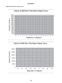
10,000 Ohm Thermistor Output Curve ................... 46
Appendix II................................................................. 47
I/O Flex 6126 Controller Specifications .................. 47
Appendix III................................................................ 48
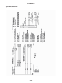
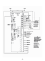
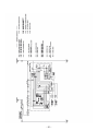
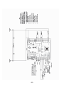
Typical Wiring Schematic ....................................... 48
Appendix IV ............................................................... 49
Typical Wiring Schematic ....................................... 49
– 21 –
OVERVIEW
A glossary has been provided to assist the reader in
understanding distinctive terms and phrases. These
terms and phrases appear in italics.
bottom of the room sensor. Because the room sensor
is hard-wired to the controller via the Rnet port on the
left-hand side of the controller and the BACview is
connected to the room sensor via the plug connection
on the bottom of the room sensor, this creates a
communications link between the BACview and the
controller without having to directly wire the BACview
to the controller.
The Aztec Digital Control System is designed to
give the user the ultimate in unit performance and
operational flexibility, adaptability, and reliability in a
user-friendly package.
The Aztec DDC system accepts single or multiple
units on the system network. Each unit ships with
a BACview remote. The operating parameters for
individual units may be input through the BACview.
A PC may also be connected to the network. This
allows the user to configure each unit separately, or
all units can be configured simultaneously. A controls
contractor can provide assistance in networking.
It is easy to move the BACview between the location
of the room sensor in the space and the unit’s location
without having to do any additional wiring. Simply
unplug the BACview from the bottom of the room
sensor in the space and take it to where the unit is
located. Then, plug the BACview into the Local Access
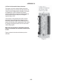
Port on the controller as shown in Figure 1. To go from
where the unit is located to the room sensor in the
space, unplug the BACview from the Local Access
Port and take it to the room sensor. Then, plug the
BACview into the bottom of the room sensor.
For MDT and MDT-Expert systems, simply plug the
BACview into the Local Access Port on the controller
as shown in Figure 1 as a room sensor is not provided
with these systems.
If there are multiple units at the jobsite, the BACview
can easily be unplugged from one unit and plugged
into another. For this reason, it is not recommended to
hardwire the BACview into the Rnet port on the lefthand side of the controller because it sacrifices the
convenience of portability.
Operational modes include time scheduling, filter
monitoring, and multiple damper control and
temperature control schemes. All of these modes
provide the maximum in unit operational flexibility.
The diagnostic capabilities of the Aztec DDC system
ensure swift response to abnormal unit conditions. An
alarm is generated anytime a conflict exists between
the operational parameters and actual unit operation.
An indication of trouble is displayed at the BACview
and system PC in text format. In the Diagnostics
section of this manual you will find a list of all alarms
and possible causes and solutions.
The BACview ships with a cable. One end of the cable
consists of a pre-wired black screw terminal connector
while the other end consists of a 5-pin red-tipped plug.
For MRT and MRT-Expert systems, plug the pre-wired
black screw terminal connector into the back of the
BACview and plug the 5-pin red-tipped plug into the
All of the features of the Aztec DDC system are
designed to provide the user with real time information.
At any time the user can display all of the operational
parameters, make changes, if necessary, and observe
the various temperature, pressure, and damper
readings. The system’s diagnostic capabilities provide
the user with up to the minute status reporting.
(BACview service module or WebCTRL internet
connection is required for these features.)
– 22 –
NETWORKING
The DDC system is adaptable to a variety of
different network architectures and protocols. Each
controller has built-in protocol translation and can be
configured for operation on ARCnet156 or EIA-485
communication networks. See Appendix II for specific
controller specifications.
The DDC system can be connected to most 3rd party
building automation systems. Some systems may
require the use of special routers, interfaces, or other
network communication devices. LON systems require
a special adapter card that must be ordered with the
unit. Ethernet systems require an interface that can
be ordered with the unit or sourced from a networking
vendor.
The BACnet device instance number for the
controller is 24000 + the rotary address setting.
The default address for all Aztec DDC units is 16,
therefore the BACnet instance number is 24016.
The DDC controller will not function if the rotary
address setting is incorrect.
DDC SYSTEM DEFAULT SETTINGS
The following is a list of Aztec DDC controller defaults.
These are the default operating parameters set at the
factory prior to shipment.
Unit Configuration
ITEM
DEFAULT
RANGE
Unit Network Address
16
00 – 99 (rotary switches)
Unit Enable
OFF
AUTO – OFF – MANUAL
3rd Party Zone Temperature Control Enable
No
No – Yes
Supply Fan VFD Operation
As specified
1 = Supply Air Temperature Control,
2 = Building Pressure Control
Mixed Air Damper Operation
As specified
1 = Building Pressure Control,
2 = Mixed Air Temperature Control,
3 = % Outside Air Control
Control System
As specified
MRT (modulating room temperature
control) –
MDT (modulating discharge
temperature control)
Stage 2 Cooling Installed
As specified
No – Yes
– 23 –
DDC SYSTEM DEFAULT SETTINGS continued
Cooling Configuration
ITEM
DEFAULT
RANGE
Fill/Drain Schedule Enable
No
No – Yes
Cooling Stage 1 (Indirect) Fill/Drain Schedule
1
1 = Monday, 2 = Tuesday,
3 = Wednesday, 4 = Thursday,
5 = Friday, 6 = Saturday, 7 = Sunday
Cooling Stage 2 (Direct) Fill/Drain Schedule
1
1 = Monday, 2 = Tuesday,
3 = Wednesday, 4 = Thursday,
5 = Friday, 6 = Saturday, 7 = Sunday
Cooling Stage 1 Fill/Drain Duration
15 minutes
Unrestricted
Cooling Stage 2 Fill/Drain Duration
15 minutes
Unrestricted
Cooling Stage 1 Drain Time
1
1 = 1:00 AM (use 24 hour format)
Cooling Stage 2 Drain Time
2
2 = 2:00 AM (use 24 hour format)
Cooling Stage 1 Runtime Drain Trip
100 hours
Unrestricted
Cooling Stage 2 Runtime Drain Trip
100 hours
Unrestricted
Cooling Stage 1 Maintenance Alarm Enable
No
No – Yes
Cooling Stage 2 Maintenance Alarm Enable
No
No – Yes
Cooling Stage 1 Maintenance Alarm Trip
2,200 hours
Unrestricted
Cooling Stage 2 Maintenance Alarm Trip
2,200 hours
Unrestricted
Temperature Setpoints
ITEM
DEFAULT
RANGE
Unoccupied Zone Setpoint
100°F
40°F — 130°F
Occupied Zone Setpoint
73°F
40°F — 130°F
Cooling Economizer Setpoint
55°F
40°F — 130°F
Supply Air Temperature Setpoint
70°F
40°F — 130°F
Cooling Stage 2 Interstage Differential
2°F
2°F — 10°F
Minimum Supply Air Temperature Setpoint
55°F
55°F — 130°F
Maximum Supply Air Temperature Setpoint
75°F
55°F — 130°F
Mixed Air Temperature Setpoint
55°F
30°F — 90°F
Freezestat Setpoint
45°F
35°F — 80°F
Outside Air Temperature to Drain Sump(s)
36°F
35°F — 80°F
Economizer Configuration
ITEM
DEFAULT
RANGE
Outside Air Temperature Trip for Economizer
65°F
50°F – 90°F
Outside Air Temperature for
Heating/Cooling Changeover
55°F
40°F – 130°F
Pressure Setpoints
ITEM
DEFAULT
RANGE
Building Pressure Setpoint
0.00” W.C.
-0.100” W.C. – +0.100” W.C.
– 24 –
DDC SYSTEM DEFAULT SETTINGS continued
Outside Air Setpoints
ITEM
DEFAULT
RANGE
% Outside Air Setpoint
20%
0% – 100%
Minimum % Outside Air Setpoint
20%
0% – 100%
VFD Speed Setpoints
ITEM
DEFAULT
RANGE
Supply Fan VFD Minimum Speed
25%
5% – 100%
Cooling Tower VFD Minimum Speed
50%
5% – 100%
UNIT OPERATING MODES
There are three different modes that control the unit
operation:
• Off
• Manual
• Auto
There are also two different methods for controlling the
operating modes:
• an intelligent room sensor and BACview panel with
LCD display
• an internet-based WebCTRL interface or other 3rd
party building automation system
Controlling the operating modes is accomplished
via the BACview panel (KP-01) with LCD display. A
detailed description of the function of these modes
follows.
MRT-Expert Controls
The Aztec MRT-Expert, modulating room temperature
control provides full information regarding unit
operation and allows the user to adjust all operational
parameters using the BACview panel. See the Menu
Selection Tree for BACview section of this user manual
for instructions that show how to change parameter
values via the BACview.
AdaptAire units configured for MRT-Expert
controls will have a fixed discharge temperature
of 70°F if the room temperature sensor is
disconnected or otherwise fails to communicate
with the unit control module.
Unit Off Mode
Off Mode is the default unit operational mode. To place
the unit in Off Mode scroll through the UNIT MODES
menu tree, locate the AUTO/OFF/MANUAL branch,
and select OFF. This will place the unit in the OFF
mode. The OFF mode prevents the fans and cooling
from starting. This mode will override the Time Clock
and Night Setback functions.
Unit Manual Mode
Manual Mode allows the supply fan and cooling tower
fan to operate regardless of the Time Clock or Night
Setback functions. Cooling functions use the Occupied
Setpoints. To place the unit in Manual Mode scroll
through the UNIT MODES menu tree, locate the
AUTO/OFF/MANUAL branch, and select MANUAL.
This will place the unit in the MANUAL mode.
Unit Auto Mode
Auto Mode has three different functions that control
the supply fan, cooling tower fan, and general unit
operation: the time clock, cooling night setback, and
a signal from an external source to an auxiliary digital
input. To place the unit in Auto Mode scroll through
the UNIT MODES menu tree, locate the AUTO/OFF/
MAN branch, and select AUTO. This will place the unit
in the AUTO mode. This activates the three Auto mode
functions.
Scheduling Time Clock
The primary Auto Mode function is the Time Clock
Schedule. The Time Clock function allows the user to
schedule the operational times of the unit. There are
four different schedules available: 24 hour continuous
operation, daily, holiday, and override. The daily
schedule can be programmed for up to 4 separate
On/Off events with any combination of days. The
daily schedule sets the typical On/Off times for the
unit. The holiday schedule can be programmed for up
to 12 separate On/Off events with any combination
of days. The holiday schedule sets the Off times for
holidays and other shutdown periods. The override
schedule can be programmed for up to 2 separate On/
Off events with any combination of days. The override
schedule sets the On times that will override the
holiday schedule. This scheduling system allows the
user to program a diverse array of On/Off operations.
The Aztec DDC system has no preset operational
schedule.
– 25 –
UNIT OPERATING MODES continued
To set the operational times of the unit scroll through
the SCHEDULES menu tree, and locate the desired
Daily, Holiday, or Override branch. Enter the days and
times for the unit to operate. In the Daily or Override
section these times should correspond to the desired
“on” times for the unit’s operation. In the Holiday
section these times should correspond to the desired
“off” times for the unit’s operation. For any schedule
to function the Use tab must be set to yes.
3. To enable the Daily schedule, set the Use field to
Yes. The Stat field indicates whether the schedule
on that screen is currently active, so you may
see either ON or OFF in this field. Navigate to
the Start Time field and set the start time for 6:00
AM. Be aware that times are programmed in a
24 hour format. For example, 2:00 PM would be
programmed as 14:00, which will show up on the
BACview screen as “14 : 0”.
To set the time clock function for 24 hour continuous
operation, scroll through the menu tree and locate the
SCHEDULES page. Set the 24 Hr Operation to yes.
Enter the Daily section of the menu and set the Use
tab to yes. Finally select the days for 24 hour operation.
4. Navigate to the Stop Time field and set the stop
time for 5:00 PM (17:00 in the 24 hour format).
See the CLOCK SET section of this manual for setting
the time, date and Daylight Savings function.
The following instructions demonstrate how to set up
a sample schedule using the BACview remote. An
example of a typical schedule would be to have the unit
On Monday through Friday from 6:00 AM to 5:00 PM,
except during the week of Thanksgiving when the unit
will be Off. The unit will run each weekday during the
Thanksgiving shutdown from 8:00 AM until noon while
a maintenance crew is in the building. The maintenance
crew will come in at 5:00 AM on Monday to complete
preliminary tasks in preparation for the week. We will
use this sample schedule as our guide in programming
the sample schedule. Refer to the Menu Selection Tree
for BACview section of this manual for more information
about the BACview buttons, hotkeys, and menus.
The sample schedule and instructions below are
just a guide; you may skip the rest of the Scheduling
Time Clock section of this manual if you are already
comfortable programming daily, holiday, and override
schedules. Simply determine what schedule you want
the unit to operate on and set the schedule in the
BACview accordingly.
1. Use the FN + 7 hotkey to jump directly to the
Schedules screen of the menu tree. While holding
the FN key, press the 7 key, and the Schedules
screen will appear. The BACview may prompt you for
the User password. The default password is 0000.
5. Navigate to the Days fields, making sure the cursor
surrounds the first hyphen ( [ - ] ). Press the Enter
button and then press the link key that corresponds
to INCR on the screen. The field will now show
MON, indicating that this schedule will be active
every Monday from 6:00 AM to 5:00 PM. Repeat
this process for each of the remaining Days fields,
except for SAT and SUN. Your screen should now
look like this:
6. The week of Thanksgiving for 2012 is from Sunday,
November 18th to Saturday, November 24th. We
want the unit to operate each weekday from 8:00
AM to 12:00 PM while the maintenance crew is
in the building during this week. We will need to
set up a few Holiday schedules to accomplish
this. Since the unit normally runs from 6:00 AM
to 5:00 PM on weekdays, we need to set the Off
periods in the Holiday schedules. The Off period
we want to schedule then is from 6:00 AM to 8:00
AM and 12:00 PM to 5:00 PM. We will use 10
Holiday schedules to accomplish this (two for each
weekday).
7. Navigate back to the Schedules screen using
the FN + 7 hotkey. Move the cursor to select the
Holiday field and press Enter. Set the start time to
6:00 AM and the stop time to 8:00 AM. Remember,
the Holiday schedules represent the period during
which the unit is to be OFF. Set the Month field to
11 (November) and the Day field to 19 (Monday,
the first weekday that week). Your screen should
now look like this:
2. Navigate to the Daily field and press the Enter
button. The screen will show a blank daily schedule.
– 26 –
UNIT OPERATING MODES continued
8. Press the link key corresponding to the Next
field on the screen. This will take you to Holiday
Schedule 2. Set the start time for Holiday Schedule
2 to 12:00 PM and the stop time to 5:00 PM. Set
the Month field to 11 (November) and the Day field
to 19 (Monday, the first weekday that week). Your
screen should now look like this:
Auxiliary Unit Enable
The Auxiliary Unit Enable function overrides all other
Auto Mode functions and cycles the unit into operation.
This function is activated whenever a contact is closed
between terminals 229 and 230 on the unit’s terminal
strip located in the unit’s main control panel. Cooling
functions use the Night Setback Setpoints. See the
Typical Wiring Schematic section of this manual for
more information. This function can be used with a
twist timer, toggle switch, door switch, exhaust fan
interlock, or any other dry contact to override the time
clock schedule.
Repeat this step for the 20th, 21st, 22nd, and 23rd
(Tuesday, Wednesday, Thursday, and Friday) using
Holiday Schedules 3 through 10, then proceed to
the next step.
MDT-Expert Controls
The Aztec MDT-Expert, modulating discharge
temperature control provides full information regarding
unit operation and allows the user to adjust all
operational parameters using the BACview panel. See
the Menu Selection Tree for BACview section of this
user manual for instructions that show how to change
parameter values via the BACview.
9. Since the maintenance crew will be in the building
at 5:00 AM on Monday, we will need an override
schedule to override part of the Holiday schedule
we just created. Navigate back to the Schedules
screen using the FN + 7 hotkey. Move the cursor to
select the Override field and press Enter. Set the
start time to 5:00 AM and the stop time to 8:00 AM.
Remember, the Override schedules override the
Holiday schedules and represent the period during
which the unit is to be ON. Set the Month field to 11
(November) and the Day field to 19 (Monday, the
first weekday of Thanksgiving week in 2012). Your
screen should now look like this:
10. Press the link key corresponding to the Home field
on the screen to return to the Home screen. The
sample schedule is programmed and the unit will
automatically turn on and shut off based on the
daily, holiday, and override schedules.
Cooling Night Setback
The Cooling Night Setback function automatically cycles
the unit “on” if the room temperature rises above the
Cooling Setback temperature setpoint and the unit is
scheduled to be “off”. If the unit is scheduled to be “off” and
the Cooling Setback function turns the unit “on”, the unit
will be cycled off once the room air temperature has fallen
2°F below the Cooling Setback setpoint. This function
toggles binary outputs BO-1 (main supply fan start/
stop), BO-2 (stage 1 cooling pump start/stop) and BO-4
(cooling tower fan start/stop). The default for the Cooling
Setback setpoint is 100°F. To change the Cooling Setback
setpoint scroll through the SETPOINTS menu tree, locate
the Cooling Setback setpoint and enter a new temperature.
The allowable temperature range is 40°F - 130°F.
Unit Off Mode
Off Mode is the default unit operational mode. To place
the unit in Off Mode scroll through the UNIT MODES
menu tree, locate the AUTO/OFF/MANUAL branch,
and select OFF. This will place the unit in the OFF
mode. The OFF mode prevents the fans and cooling
from starting. This mode will override the Time Clock
function.
Unit Manual Mode
Manual Mode allows the supply fan and cooling tower
fan to operate regardless of the Time Clock function. To
place the unit in Manual Mode scroll through the UNIT
MODES menu tree, locate the AUTO/OFF/MANUAL
branch, and select MANUAL. This will place the unit in
the MANUAL mode.
Unit Auto Mode
Auto Mode has two different functions that control
the supply fan, cooling tower fan, and general unit
operation: the time clock and a signal from an external
source to an auxiliary digital input. To place the unit
in Auto Mode scroll through the UNIT MODES menu
tree, locate the AUTO/OFF/MAN branch, and select
AUTO. This will place the unit in the AUTO mode. This
activates the two Auto mode functions.
Scheduling Time Clock
The primary Auto Mode function is the Time Clock
Schedule. The Time Clock function allows the user to
schedule the operational times of the unit. There are
four different schedules available: 24 hour continuous
operation, daily, holiday, and override. The daily
schedule can be programmed for up to 4 separate On/
Off events with any combination of days. The daily
schedule sets the typical On/Off times for the unit.
– 27 –
UNIT OPERATING MODES continued
The holiday schedule can be programmed for up
to 12 separate On/Off events with any combination
of days. The holiday schedule sets the Off times for
holidays and other shutdown periods. The override
schedule can be programmed for up to 2 separate On/
Off events with any combination of days. The override
schedule sets the On times that will override the
holiday schedule. This scheduling system allows the
user to program a diverse array of On/Off operations.
The Aztec DDC system has no preset operational
schedule.
To set the operational times of the unit scroll through
the SCHEDULES menu tree, and locate the desired
Daily, Holiday, or Override branch. Enter the days and
times for the unit to operate. In the Daily or Override
section these times should correspond to the desired
“on” times for the unit’s operation. In the Holiday
section these times should correspond to the desired
“off” times for the unit’s operation. For any schedule
to function the Use tab must be set to yes.
To set the time clock function for 24 hour continuous
operation, scroll through the menu tree and locate
the SCHEDULES page. Set the 24 Hr Operation to
yes. Enter the Daily section of the menu and set the
Use tab to yes. Finally select the days for 24 hour
operation.
See the CLOCK SET section of this manual for setting
the time, date and Daylight Savings function.
See the MRT-Expert Controls section of the manual for
a step-by-step walkthrough guide that demonstrates
how to program a schedule via the BACview interface.
Auxiliary Unit Enable
The Auxiliary Unit Enable function overrides all other
Auto Mode functions and cycles the unit into operation.
This function is activated whenever a contact is closed
between terminals 229 and 230 on the unit’s terminal
strip located in the unit’s main control panel. Cooling
functions use the Occupied Setpoints. See the Typical
Wiring Schematic section of this manual for more
information. This function can be used with a twist
timer, toggle switch, door switch, exhaust fan interlock,
or any other dry contact to override the time clock
schedule.
The MDT-EXPERT control does not support the night
setback functions.
– 28 –
VENTILATING AND COOLING OPERATING MODES
The Aztec DDC controller automatically switches
between the ventilating and cooling modes of
operation. The previous sections described the Cooling
Setback operation. This section concentrates primarily
on the Occupied operating modes.
Ventilation Mode
Ventilation Mode occurs when the fan is running but
the unit is not providing cooling.
The ventilation mode is dependent on the room (MRTExpert) or outside air (MDT-Expert) temperature
relative to the room or outside air temperature setpoint.
The relationship between these values is described in
the Cooling Mode section of this manual.
Cooling Mode
During the Occupied Cooling mode, Cooling Stage
1 is activated whenever the room or outside air
temperature is 2°F above the Occupied Zone setpoint
and is deactivated at the Occupied Zone setpoint.
Cooling Stage 2 is activated whenever the room or
outside air temperature is 2°F above the Occupied
Zone setpoint plus the Cooling Stage 2 Interstage
Differential setpoint (the default value is 2°F and is
user-configurable via the BACview) and is deactivated
2°F above the Occupied Zone setpoint.
During the Unoccupied Cooling mode (MRT-Expert
systems only), Cooling Stage 1 is activated whenever
the room or outside air temperature is at the Cooling
Night Setback setpoint and is deactivated 2°F below
the Cooling Night Setback setpoint.
General Cooling Control
For MRT-Expert control systems, the cooling will
cycle on and off as required to maintain a constant
temperature. The cooling outputs (BO-2 & BO-3) can
be protected by an anti-cycle timer which has a 3
minute off / 3 minute on delay. The anti-cycle timer
is enabled by default. To disable the anti-cycle timer,
scroll through the UNIT SETUP menu tree using the
BACview, locate the Use Clg Anti-Cycle Timer field,
and set its value to No.
To change the desired cooling room temperature of
an MRT-Expert control system, scroll through the
SETPOINTS menu tree using the BACview, locate
the Occ Zone Stpt, and enter a new temperature. The
allowable temperature range is 40°F - 130°F.
For MDT-Expert control systems, the cooling will
cycle on and off as required to maintain a constant
discharge temperature.
For MRT-Expert control systems, the controller cycles
the cooling on and off to maintain the supply air
temperature within a defined operating window. This
window defines the maximum and minimum discharge
temperatures.
To change the desired cooling discharge temperature
of a MDT-Expert control system, scroll through the
SETPOINTS menu tree using the BACview, locate
the Supply Air Temp Stpt, and enter the desired
temperature. The allowable temperature range is 40°F
- 130°F.
To change the desired minimum supply or discharge
air temperature scroll through the SETPOINTS menu
tree, locate the Min Sup Air Temp Stpt, and enter
a new temperature. This temperature must not be
greater than the Max Sup Air Temp Stpt. The allowable
temperature range is 40°F - 130°F. This sets the lowest
discharge air temperature that will leave the unit.
Cooling Stage 2 is activated whenever the room
or outside air temperature is at the Cooling Night
Setback setpoint plus the Cooling Stage 2 Interstage
Differential setpoint and is deactivated at the Cooling
Night Setback setpoint.
Energy Savings Mode
The Energy Savings Mode will automatically disable
the cooling if the outside air temperature is below the
Cooling Economizer setpoint. This function is similar
to an inlet duct thermostat. The cooling will cycle back
on if the outside air temperature rises 3°F above the
Cooling Economizer setpoint.
To change the desired cooling economizer
temperature scroll through the SETPOINTS menu tree,
locate the Cooling Economizer setpoint, and enter a
new temperature. The default for this setpoint is 55°F.
The allowable temperature range is 40°F - 130°F.
To change the desired maximum supply or discharge
air temperature scroll through the SETPOINTS menu
tree, locate the Max Sup Air Temp Stpt, and enter a new
temperature. This temperature must not be less than
the Min Sup Air Temp Stpt. The allowable temperature
range is 40°F - 130°F. This sets the highest discharge
air temperature that will leave the unit.
If the maximum and minimum discharge temperature
setpoints are set for the same temperature, the supply
air temperature will be the same as the setpoint
regardless of the room temperature setpoint or actual
room temperature.
– 29 –
VARIABLE FREQUENCY DRIVE OPERATION
The Aztec DDC system features a variable frequency
drive (VFD) to control the main supply fan motor and
an optional VFD to control the cooling tower fan motor.
The DDC controller modulates the speed of the main
supply fan motor and cooling tower fan motor based on
the unit modes as configured via the BACview. Unless
otherwise specified during ordering, all units ship from
the factory with supply air temperature control as the
default control mode for both the main supply fan VFD
and the optional cooling tower fan VFD.
Main Supply Fan VFD Control
The supply fan speed varies based on one of two modes:
supply air temperature control or building pressure control.
In supply air temperature control mode, the supply
fan speed varies based on the supply air temperature.
The controller modulates the output to the supply fan
VFD using a PID loop that compares the supply air
temperature to the supply air temperature setpoint.
The controller will modulate the speed of the main supply fan
motor to maintain the supply air temperature between the
minimum and maximum supply air temperature setpoints.
The main supply fan VFD will modulate the supply
fan motor toward its minimum speed as the supply
air temperature falls to the minimum supply air
temperature setpoint. The main supply fan VFD will
modulate the supply fan motor toward its maximum
speed as the supply air temperature rises to the
maximum supply air temperature setpoint.
The controller will modulate the speed of the cooling tower
fan motor to maintain the supply air temperature between the
minimum and maximum supply air temperature setpoints.
As the supply air temperature rises to the supply air
temperature setpoint, the cooling tower fan motor and
stage 1 circulating pump are enabled. As the supply
air temperature rises above the supply air temperature
setpoint plus the Cooling Stage 2 Interstage Differential
setpoint, the stage 2 circulating pump is enabled.
As the supply air temperature rises above setpoint,
the controller signals the VFD to increase the speed
of the cooling tower fan motor, thereby increasing the
evaporative cooling effect of the media.
As the supply air temperature falls below setpoint, the
controller signals the VFD to decrease the speed of the
cooling tower fan motor. Then, the cooling tower fan motor
and cooling outputs are disabled until a call for cooling is
present again.
The cooling tower fan VFD will approach its minimum
speed as the supply air temperature approaches the
minimum supply air temperature setpoint. The cooling
tower fan motor and cooling outputs are disabled until a
call for cooling is present again.
In building pressure control mode, the controller
modulates the output to the supply fan VFD using a PID
loop to maintain the building pressure at the building
pressure setpoint.
As the building pressure rises above setpoint, the
controller signals the VFD to decrease the speed of
the main supply fan motor, thereby decreasing the
building pressure until the building pressure equals the
building pressure setpoint.
As the building pressure falls below setpoint, the controller
signals the VFD to increase the speed of the main supply
fan motor, thereby increasing the building pressure until
the building pressure equals the building pressure setpoint.
The main supply fan VFD will modulate the supply fan
motor toward its minimum speed as the building pressure
approaches the Building Pressure setpoint. The main
supply fan VFD will modulate the supply fan motor toward
its maximum speed as the building pressure falls to the
Building Pressure setpoint.
Cooling Tower Fan VFD Control
The cooling tower fan speed varies based on the supply
air temperature. The controller modulates the output to
the cooling tower fan VFD using a PID loop that compares
the supply air temperature to the supply air temperature
setpoint.
Manual Override
The administrator password for the BACview is required in
order to use the manual overrides.
The supply fan VFD analog control output (AO-2) and the
cooling tower fan analog control output (AO-3) can be
controlled manually via the OVERRIDES branch of the
BACview menu tree by adjusting the speed of each fan
motor as a percentage of full speed. First, set the desired
supply fan speed percentage. Then, toggle the “Lock SF
VFD (AO-2)?” field to YES. The controller will now force
the supply fan VFD to drive the supply fan motor at this
percentage of full speed until the “Lock SF VFD (AO-2)?”
field is toggled to off. The same process can be repeated
for the cooling tower fan analog output (AO-3) if the unit is
equipped with the optional cooling tower VFD.
WARNING: Manually overriding the supply and
cooling tower fan motor analog outputs disables
automatic motor speed modulation functions and
may result in poor unit performance as the variable
frequency drive(s) will not be able to modulate the
motor(s) to optimize performance as environmental
conditions change.
– 30 –
MIXED AIR DAMPER CONTROL MODES
There are three different modes that control the unit
damper operation: Mixed Air Temperature, Building
Pressure, and Percentage of Outside Air control.
These operating modes are selected through the menu
tree of the BACview or PC. Not all damper modes are
available on all units.
The mixed air dampers also have an economizer
function to reduce energy consumption based on
outside air conditions, thereby improving unit efficiency.
The economizer function is described at the end of
the Mixed Air Damper Control Modes section of this
manual.
Outside air dampers will remain closed during the
unoccupied period if the supply fan is off or if the room
temperature is less than 45°F and the supply fan is
running.
Mixed Air Temperature Control
Mixed Air Temperature control varies the percentages
of outside air and return air to maintain a constant
mixed air temperature.
To place the damper operation in Mixed Air
Temperature mode scroll through the menu tree,
locate the UNIT MODES branch and select MA Temp
Ctrl. Next, scroll through the menu tree, locate the
SETPOINTS branch, select Mixed Air, and enter the
desired temperature. The allowable range is 30°F 90°F.
Building Pressure Control
Building Pressure control varies the percentages
of outside air and return air to maintain a constant
pressure within the space. A pressure transducer
measures the pressure within the space relative to
the pressure exterior to the space and transmits a
corresponding signal to the Aztec DDC controller. The
controller compares this signal to the desired building
pressure setpoint and uses a PID loop to modulate
the outside air and return air dampers to maintain the
specified building pressure.
To place the damper operation in Building Pressure
mode scroll through the menu tree, locate the UNIT
MODES branch and select Bldg Pres Ctrl. Next, scroll
through the menu tree, locate the SETPOINTS branch,
select Bldg Pressure Stpt, and enter the desired
pressure. The allowable range is –0.100” W.C. to
+0.100” W.C.
NOTE: If the Supply Fan Operation and Mixed Air
Damper Operation modes are both set to Building
Pressure control, the Mixed Air Damper Control
mode will automatically switch from Building
Pressure control to Percentage of Outside Air
Control. To select Building Pressure control for
Mixed Air Damper Operation mode, you must
change the Supply Fan Operation mode to Supply
Air Temperature control.
Percentage of Outside Air Control
To place the damper operation in Percentage of
Outside Air mode scroll through the menu tree, locate
the UNIT MODES branch and select % Outside
Air Ctrl. Next, scroll through the menu tree, locate
the SETPOINTS branch, select % OA Setpoint and
enter the desired percentage open for the outside air
dampers. The damper actuators will drive the outside
air dampers open to the Min % OA setpoint or the %
OA setpoint, whichever is greater.
Automatic Economizer
The unit operates in economizer mode when the
outside air dry bulb temperature is below 65°F and
the outside air enthalpy is below 25 btu/lb·m. Once
these conditions are satisfied, the outside air dampers
begin to modulate open to provide free cooling in
the space. The outside air temperature economizer
setpoint and outside air enthalpy economizer setpoint
are adjustable via the SETPOINTS branch of the menu
tree in the BACview.
The DDC controller calculates the outside air enthalpy
automatically based on the outside air dry bulb
temperature and the outside air relative humidity. The
automatic economizer overrides mixed air temperature
control and percentage of outside air control but does
not override building pressure control or the 100%
outside air function.
– 31 –
100% OUTSIDE AIR
The 100% Outside Air function automatically opens the
outside air dampers and closes the return air dampers.
This function is activated whenever a contact is
closed between the appropriate terminals on the unit’s
terminal strip located in the unit’s main control panel.
See the Typical Wiring Schematic and Multiplexed
Input sections of this manual for more information.
The 100% Outside Air function overrides all other
damper control functions.
AUTOMATIC FILL AND DRAIN CONTROL
General Fill and Drain Operation
The automatic fill and drain binary outputs for cooling
stages 1 and 2 (BO-5 and BO-6, respectively) are
controlled independently of each other. The fill and
drain valves are controlled via either a user-specified
schedule or a runtime odometer. Switching between
these control modes is accomplished through the
provided BACview device. The Cooling Stage 1 and 2
Water Level Failure Alarms are disabled when cooling
stages 1 and 2 are drained as commanded by the
user-specified schedule or runtime odometer.
as the unit is in the unoccupied mode. If the unit is in
the occupied mode when the trip point is reached, the
sump(s) will drain the next time the unit switches to
unoccupied mode. The runtime trip setpoint for each
stage of cooling can be set via the BACview. The
factory-default value for the Cooling Stage 1 and 2
Runtime setpoints is 100 cumulative hours of runtime.
Once the drain cycle is complete, the outputs will
energize and the fill cycle will begin, filling the unit with
water. The outputs remain energized until the next time
the drain cycle begins.
The binary outputs are energized by default to hold
the fill valve open and the drain valve(s) closed during
normal unit operation. Once the DDC controller calls
for a drain cycle (based on the user-configurable
schedule), the binary outputs will be de-energized
for a minimum of 15 minutes (user-configurable via
the BACview) to allow the unit ample time to drain its
sump(s).
Outside Air Temperature to Drain Sump(s)
If the outside air temperature falls below the OA Temp
to Drain Sump(s) setpoint (the default is 36°F and is
user-configurable via the BACview), the cooling stage
1 and 2 fill/drain binary outputs (BO-5 and BO-6) will
de-energize and the fill and drain valves will return
to their normally closed and normally open positions
respectively. The sump(s) will drain. The Cooling Stage
1 and 2 Water Level Failure alarms will be disabled.
The DDC controller will neither re-energize the binary
outputs nor re-enable the alarms until the outside air
temperature rises 5°F above the OA Temp to Drain
Sump(s) setpoint.
Once the drain cycle is complete, the outputs will
energize and the fill cycle will begin, filling the sump(s)
with water. With the drain cycle complete and the
supply air temperature rising, the outputs will energize
and the fill cycle will begin when the zone or supply
air temperature is within 5°F of the zone or supply air
temperature setpoint. This temperature deadband is
user-configurable via the BACview. The outputs remain
energized until the next time the drain cycle begins.
User-Specified Schedule
The DDC controller will drain the sump(s) when the
current date and time match the user-programmed
date and time (user-configurable via the BACview)
as long as the unit is in the unoccupied mode. For
example, the indirect section (stage 1) could be
programmed to drain every Monday morning at 1:00
AM and the direct section (stage 2) every Monday
morning at 3:00 AM, so as not to interfere with cooling
demands during the occupied period.
Runtime Odometer
The DDC controller will drain the indirect section when
the cumulative stage 1 runtime reaches the Cooling
Stage 1 Runtime Trip setpoint and will drain the direct
section when the cumulative stage 2 runtime reaches
the Cooling Stage 2 Runtime Trip setpoint, as long
Manual Override
The administrator password for the BACview is
required in order to use the manual overrides.
The off/on state of the fill and drain outputs (BO5 and BO-6) can be controlled manually via the
OVERRIDES branch of the BACview menu tree to
induce manual fill and drain cycles. Toggle the “Lock
Stg 1 Fl/Drn (BO5)?” field to ON (fill) or OFF (drain) to
force the cooling stage 1 fill and drain output on or off
depending on the desired state. To enable this change
and lock the output in the desired state, toggle the No/
Yes field from NO to YES. Once any manual fill/drain
cycles are complete, unlock the outputs by toggling the
No/Yes field of the binary output from YES to NO. The
same process can be repeated for the stage 2 fill and
drain output (BO-6).
WARNING: Manually overriding these binary
outputs disables all automatic fill and drain
functions described in this section and could
result in severe damage to the equipment.
– 32 –
ELECTRICAL DEMAND AND USAGE MONITORING
A current transducer monitors the instantaneous amp
draw of all loads in the unit and inputs that information
to the DDC controller via a 4-20 mA DC signal. The
control program multiplies the instantaneous amp
draw by the unit design voltage to calculate the
instantaneous demand in kilowatts (kW). Cumulative
electrical usage is calculated by multiplying the
instantaneous demand by the unit runtime. The DDC
controller retains the following information in memory
and stores the data as BACnet readable points
(contact factory for Aztec DDC Points List).
•
•
•
•
•
•
•
•
•
•
•
•
•
Instantaneous Demand
Peak Demand Today
Peak Demand Yesterday
Peak Demand Month to Date
Peak Demand Last Month
Peak Demand Year to Date
Peak Demand Last Year
Usage Today
Usage Yesterday
Usage Month to Date
Usage Last Month
Usage Year to Date
Usage Last Year
A reset function is provided on the ELECTRICAL
DEMAND branch of the BACview menu tree to allow
the operator to reset all electrical usage and demand
data to zero.
Usage and demand data cannot be recovered once
they are purged from the system via reset.
kW
kW
kW
kW
kW
kW
kW
kWh
kWh
kWh
kWh
kWh
kWh
COMFORT INDEX AND SATISFACTION RATING
The Comfort Index (CI) and Satisfaction Rating (SR)
features of the control program allow the operator to
make an at-a-glance assessment of unit performance
via the BACview.
Comfort Index
The DDC controller calculates the Comfort Index using
the ratio of the absolute value of the zone temperature
(MRT-Expert) or supply air temperature (MDT-Expert)
minus the zone or supply air temperature setpoint to
the zone or supply air temperature setpoint.
For example: in an MRT-Expert system, if the zone
temperature is 75°F and the zone temperature setpoint
is 73°F, the Comfort Index would be as follows:
As the zone or supply air temperature approaches
the zone or supply air temperature setpoint, the
Comfort Index will increase, reaching 100% when the
temperature equals the setpoint.
Satisfaction Rating
The DDC controller calculates the Satisfaction Rating
as the ratio of the satisfied runtime to the total unit
runtime. The satisfied runtime is defined to be the
amount of time during which the zone temperature is
less than or equal to the zone temperature setpoint
plus 2°F (MRT-Expert) or the supply air temperature
less than or equal to the supply air temperature
setpoint plus 10°F (MDT-Expert).
For example, if the zone or supply air temperature
has been below the zone or supply air temperature
setpoint for 1337 hours and the unit has been on
for 1400 hours, the Satisfaction Rating would be as
follows:
Periodically check the Comfort Index and Satisfaction
Rating values via the BACview to ensure the unit is
operating effectively. Low percentages for either of
these points could indicate an suboptimal setpoint
configuration.
Verify that all setpoints on the SETPOINTS branch
of the BACview menu tree are reasonable and that
no values were entered into the system incorrectly
as this may negatively impact unit performance.
– 33 –
FREEZESTAT
The Freezestat function automatically cycles the unit off
if the supply air temperature drops below the Freezestat
setpoint for 3 continuous minutes. On all units there is
an initial 8-minute delay prior activation. The Freezestat
function prevents the unit from starting. The default for
this setpoint is 45°F. To change the Freezestat setpoint
scroll through the menu tree, locate the SETPOINTS
branch of the BACview menu tree, select Freezestat
SP, and enter a new temperature. The allowable
temperature range is 35°F - 80°F.
The Cooling Stage 1 and 2 Water Level Failure alarms
are disabled while the Freezestat alarm is active.
CLOGGED FILTER
An optional clogged filter switch is required for this
function. The Clogged Filter function automatically
notifies the user of a dirty filter condition. A Clogged
Filter indication will appear on the BACview. This
function is activated whenever a contact is closed
between terminals 227 and 228 on the unit’s terminal
strip located in the unit’s main control panel. See the
Typical Wiring Schematic section of this manual for
more information.
– 34 –
UNIT RESETS
This section should assist the user in resetting alarms
and cycle counters which have been displayed on the
BACview.
WARNING: Activating a reset purges and renders
irretrievable all previously accumulated data for that
particular status feature.
Cooling Stage 1 Starts Reset
To reset the record of the number of times cooling stage
1 has cycled on, scroll through the menu tree, locate
the UNIT RESETS branch and select Cooling Stage 1
Starts Reset. Press the Enter key. The word OFF should
flash. Now press the INC key and the word ON should
flash on the display. Press the Enter key again and ON
should stop flashing. Repeat this process so the word
OFF is displayed and not flashing. The Cooling Stage
1 Starts value has now been reset to zero and the
Cooling Stage 1 Starts function has been rearmed.
Cooling Stage 2 Starts Reset
To reset the record of the number of times cooling stage
2 has cycled on, scroll through the menu tree, locate
the UNIT RESETS branch and select Cooling Stage 2
Starts Reset. Press the Enter key. The word OFF should
flash. Now press the INC key and the word ON should
flash on the display. Press the Enter key again and ON
should stop flashing. Repeat this process so the word
OFF is displayed and not flashing. The Cooling Stage
2 Starts value has now been reset to zero and the
Cooling Stage 2 Starts function has been rearmed.
Cooling Stage 1 Runtime Reset
To reset the record of the length of time cooling stage 1
has been running, scroll through the menu tree, locate
the UNIT RESETS branch and select Cooling Stage
1 Runtime Reset. Press the Enter key. The word OFF
should flash. Now press the INC key and the word ON
should flash on the display. Press the Enter key again
and ON should stop flashing. Repeat this process so
the word OFF is displayed and not flashing. The Cooling
Stage 1 Runtime value has now been reset to zero
and the Cooling Stage 1 Runtime function has been
rearmed.
Cooling Stage 2 Runtime Reset
To reset the record of the length of time cooling stage 2
has been running, scroll through the menu tree, locate
the UNIT RESETS branch and select Cooling Stage
2 Runtime Reset. Press the Enter key. The word OFF
should flash. Now press the INC key and the word ON
should flash on the display. Press the Enter key again
and ON should stop flashing. Repeat this process so
the word OFF is displayed and not flashing. The Cooling
Stage 2 Runtime value has now been reset to zero
and the Cooling Stage 2 Runtime function has been
rearmed.
Electrical Usage/Demand Reset
To reset the record of the electrical usage and demand,
scroll through the menu tree, locate the UNIT RESETS
branch and select Electrical Usage and Demand Reset.
Press the Enter key. The word OFF should flash. Now
press the INC key and the word ON should flash on
the display. Press the Enter key again and ON should
stop flashing. Repeat this process so the word OFF
is displayed and not flashing. The Electrical Usage
and Demand values have now been reset to zero and
the Electrical Usage and Demand function has been
rearmed.
Satisfaction Rating Timers Reset
To reset the satisfaction rating timers (the satisfied
time timer and total runtime timer), scroll through the
menu tree, locate the UNIT RESETS branch and select
Satisfaction Rating Timers Reset. Press the Enter key.
The word OFF should flash. Now press the INC key
and the word ON should flash on the display. Press the
Enter key again and ON should stop flashing. Repeat
this process so the word OFF is displayed and not
flashing. The Satisfaction Rating timer values have now
been reset to zero and the Satisfaction Rating function
has been rearmed.
Alarms Reset
To reset all active alarms, scroll through the menu
tree, locate the Unit Resets branch and select Alarm.
Press the Enter key. The word OFF should flash. Now
press the INC key and the word ON should flash on
the display. Press the Enter key again and ON should
stop flashing. Repeat this process so the word OFF is
displayed and not flashing. The alarm has now been
cleared and the Alarm RS function has been rearmed.
See the Menu Selection Tree for BACview section of
this manual for more information about navigating the
BACview menus.
Always change the Alarm Reset parameter to OFF
after resetting the alarms.
If the Alarms Reset parameter was left in the ON state
continuously, the alarms can still trigger on alarm
conditions, however, to reset the alarms from this state
you must move change the Alarm Reset parameter to
OFF, then ON, then OFF again. Otherwise, the alarms
will not reset and you will not be alerted if an alarm
that was previously triggered happens to trigger again
during the period the alarm remained active.
A history of alarms can be viewed on the Alarms screen
of the BACview. To view the alarms history, locate the
Alarms page in the BACview menu tree. The alarms
history shows active alarms, alarms that have returned
to normal, and manually cleared alarms.
– 35 –
MULTIPLEXED INPUTS
DDC controllers are designed with a finite number
of inputs and outputs. Multiplexing expands the
functionality of the controller by allowing multiple
devices to effectively share the same input. This is
usually accomplished by connecting resistors, either in
a series or parallel configuration, to an analog input. A
switch is used in conjunction with each resistor. When
a switch is closed, the resistance at the controller input
changes. This allows the controller to identify which
switch has closed. The controller is programmed to
associate each different resistance with a specific
function. The Aztec DDC system uses a multiplexed
input only on units equipped two stages of cooling.
The user is notified of the low water level condition
through the BACview. The indirect and direct section
pumps are each equipped with a float switch and the
controller can enable/disable cooling stages 1 and
2 individually based on sensed water levels in each
section of the unit. A stage of cooling can only be
enabled if its corresponding low water level float switch
is closed. The resistance measured at the controller
input (UI-03) changes state based on which switches
are closed, as shown in the following table.
Resistance at UI-03 as a Function of Float Switch States
Resistance at Controller Input
(UI-03)
Cooling Stage 1 Low Water Level
Float Switch (SW-10)
Cooling Stage 2 Low Water Level
Float Switch (SW-11)
Closed
Closed
0Ω
Open
Closed
4.02 kΩ
Closed
Open
8.06 kΩ
Open
Open
12.08 kΩ
CLOCK SET
The Clock Set function is used to set the current time
and date as well as enabling Daylight Saving Time.
To set the clock scroll through the menu tree, locate
the CLOCKSET branch, select Date, and enter a
new date and time. Select DST to enable Daylight
Saving Time. Daylight Saving Time is the default. For
your convenience Daylight Saving Time has been
preprogrammed for the next several years. To reset the
starting and ending DST dates scroll through the DST
menu tree, locate the desired year, and enter a new
date. If your area does not subscribe to Daylight
Saving Time, set the AMOUNT value to 000.
DUCT FURNACE (IFD) CONTROL
For Aztec units equipped with an IFD-160, 320, or
480, the Aztec DDC controller outputs a 0-5 VDC
signal from AO-4 (supply air temperature control
output), which is then input to the IFD DDC controller
at IN-1. The IFD DDC controller then outputs 0-10
VDC to the modulating gas valve motor to control the
burner.
For Aztec units equipped with an IFD-800 or 1120,
the Aztec DDC controller outputs a 0-10 VDC
signal from AO-4, which is then input directly to the
modulating gas valve motor to control the burner.
Based on the duct furnace size, the controller outputs
the maximum 5 or 10 VDC (as described in the
preceding paragraphs in this section) from AO-4 when
the supply air temperature is 2°F below the supply
air temperature setpoint. The controller modulates
the output downward to 0 VDC as the supply air
temperature increases to 2°F above the supply air
temperature setpoint.
Refer to the IFD Series Duct Furnaces Installation,
Operation, and Maintenance Manual for detailed
information about duct heater operation.
– 36 –
DIAGNOSTICS – CRITICAL ALARMS
This section should assist the user in troubleshooting critical alarms that have been displayed on the BACview.
These faults require the operator to correct the condition and reset the alarm before normal unit operation resumes.
Alarm
Cause
Remedy
A. Freeze Alert.
1. Low supply air temperature.
1. Wait for the supply air temperature
to rise above the Freezestat setpoint.
Reset the alarm via the UNIT
RESETS menu tree in the BACview.
2. Unplug the input jack from the
controller. Did the display change to
-40°F or less?
a. No. There is a short in the
controller input. Replace the
controller.
b. Yes. Disconnect the sensor
wiring at the sensor. Connect an
ohmmeter to the sensor. If it is
shorted replace the sensor. At
77°F the resistance should be
10KΩ. See thermistor output curve
for other temperatures. If it is not
shorted, there is a short in the
wiring between the sensor and
the input plug. Determine cause
and rectify. Refer to Appendix II for
a typical 10KΩ thermistor output
curve.
3. Jumper the input for the sensor. Did
the display change to 150°F or more?
a. No. There is an open in the
controller input. Replace the
controller.
b. Yes. Disconnect the sensor
wiring at the sensor. Connect an
ohmmeter to the sensor. If it is
open replace the sensor. At 77°F
the resistance should be 10KΩ.
See thermistor output curve for
other temperatures. If it is not
open, there is a break in the wiring
between the sensor and the input
plug. Determine cause and rectify.
2. Sensor circuit or the sensor itself is
shorted.
3. Sensor circuit or the sensor itself is
open.
– 37 –
DIAGNOSTICS – CRITICAL ALARMS continued
B. Zone Sensor
1. Room sensor disconnected.
Failure. The zone
sensor has failed to
communicate usable
data to the controller
for more than 6
seconds.
2. Short in room sensor wiring.
C. Supply Air Sensor
1. Sensor circuit or sensor itself shorted.
Failure. The
supply air sensor
is providing the
controller with invalid
temperature data.
2. Sensor circuit or sensor itself open.
– 38 –
1. Is the zone temperature as displayed
on the UNIT STATUS branch of the
BACview menu tree less than 0°F?
a. Yes. The room sensor is
disconnected. Reconnect the
room sensor by verifying that no
wires have come loose and that
the terminal block connectors that
bring the wires from the room
sensor to the controller are also
securely in place.
b. No. Continue.
2. Is the zone temperature as displayed
on the UNIT STATUS branch of the
BACview menu tree greater than
200°F?
a. Yes. There is a short in the room
sensor wiring. Determine cause of
short and rectify.
b. No. There is a problem with the
room sensor electronics. Contact
factory.
1. Unplug the input jack from the
controller. Did the display change to
-40°F or less?
a. No. There is a short in the controller
input. Replace the controller.
b. Yes. Disconnect the sensor
wiring at the sensor. Connect an
ohmmeter to the sensor. If it is
shorted replace the sensor. At
77°F the resistance should be
10KΩ. See thermistor output curve
for other temperatures. If it is not
shorted, there is a short in the
wiring between the sensor and
the input plug. Determine cause
and rectify. Refer to Appendix II for
a typical 10KΩ thermistor output
curve.
2. Jumper the input for the sensor. Did
the display change to 150°F or more?
a. No. There is an open in the
controller input. Replace the
controller.
b. Yes. Disconnect the discharge
air temperature sensor wiring
at the sensor. Connect an
ohmmeter to the sensor. If it is
open replace the sensor. At 77°F
the resistance should be 10KΩ.
See thermistor output curve for
other temperatures. If it is not
open, there is a break in the wiring
between the sensor and the input
plug. Determine cause and rectify.
DIAGNOSTICS – CRITICAL ALARMS continued
D. Cooling Stage 1
Water Level Failure.
1. Low water level in indirect sump.
2. Fill valve closed and/or drain valve
open.
E. Cooling Stage 2
Water Level Failure.
1. Low water level in direct sump(s).
2. Fill valve closed and/or drain valve
open.
– 39 –
1. Rectify water level. See recommended
float level adjustment in the
Aztec Installation, Operation, and
Maintenance section of this manual.
The depth of the water in the sump(s)
should be half an inch below the top
of the sump’s overflow stand pipe.
2. Check valve positions and wiring.
a. The fill valve should be open when
BO-5 is energized (as indicated
by the illuminated LED). If the fill
valve is closed, check the wiring. If
the wiring is correct, then the valve
is bad. Replace the fill valve.
b. The drain valve should be closed
when BO-5 is energized (as
indicated by the illuminated LED).
If the drain valve is open, it is
malfunctioning and the wiring
should be verified. If the wiring
is correct, then the valve is bad.
Replace the drain valve.
1. Rectify water level. See recommended
float level adjustment in the
Aztec Installation, Operation, and
Maintenance section of this manual.
The depth of the water in the sump(s)
should be half an inch below the top
of the sump’s overflow stand pipe.
2. Check valve positions and wiring.
a. The fill valve should be open when
BO-6 is energized (as indicated
by the illuminated LED). If the fill
valve is closed, check the wiring. If
the wiring is correct, then the valve
is bad. Replace the fill valve.
b. The drain valve should be closed
when BO-6 is energized (as
indicated by the illuminated LED).
If the drain valve is open, it is
malfunctioning and the wiring
should be verified. If the wiring
is correct, then the valve is bad.
Replace the drain valve.
DIAGNOSTICS – NON-CRITICAL ALARMS
This section should assist the user in troubleshooting critical alarms that have been displayed on the BACview.
These faults require the operator to correct the condition and reset the alarm before normal unit operation resumes.
Alarm
Cause
Remedy
A. Unit Off/Fan On.
The controller has
not activated the
unit enable output
to start the fan,
but the fan status
input is receiving a
signal that the fan is
running. This alarm
resets automatically
once this conflict is
resolved.
If the fan is running:
1. Controller’s supply fan start/stop
output (BO-1) is energized.
2. Controller’s supply fan start/stop
output (BO-1) is shorted.
3. The unit enable relay (RE-57) and/
or main airflow switch (PS-10) is
energized.
4. Main airflow switch’s (PS-10)
normally-open contact is closed.
5. Continuity at the controller between
the fan status terminals (226 and
227).
If the fan is not running:
1. Main airflow switch’s (PS-10)
normally-open contact is closed.
2. There is a short in the wiring between
the fan status terminals (226 and 227).
B. Unit On/Fan Off.
The controller has
activated the unit
enable output to
start the fan, but
the fan status input
is not receiving a
signal that the fan is
running. This alarm
resets automatically
once this conflict is
resolved.
If the fan is running:
1. The BACview is indicating that
another existing alarm condition is
preventing the fan from running.
2. The unit enable relay (RE-57) and/
or main airflow switch (PS-10) is
energized.
3. Main airflow switch’s (PS-10)
normally-open contact is closed.
4. There is an open in the wiring
between the fan status terminals (226
and 227).
If the fan is not running:
1. The BACview is indicating that
another existing alarm condition is
preventing the fan from running.
2. Controller’s supply fan start/stop
output (BO-1) LED is lit.
3. Unit enable relay (RE-57) is energized
or its normally open contact is closed.
4. VFD tripped out on an overload fault
(the LCD on the VFD will display an
“F_PF” message).
– 40 –
1. There is a problem with the controller.
Contact factory.
2. Contact factory.
3. There is a short in the wiring.
Determine cause and rectify.
4. Replace main airflow switch.
5. There is a short in the wiring between
these terminals. Determine cause and
rectify.
1. Replace main airflow switch.
2. Determine cause and rectify
1. Determine cause and rectify.
2. There is a short in the wiring.
Determine cause and rectify.
3. Replace main airflow switch.
4. Determine cause and rectify.
1. Determine cause and rectify.
2. Replace controller.
3. There is an open in the wiring.
Determine cause and rectify.
4. Determine cause, rectify, and reset.
DIAGNOSTICS – NON-CRITICAL ALARMS continued
1. Clean or replace filters.
2. Clear obstruction.
C. Clogged Filter. The
filter air pressure
switch has closed
between the
appropriate terminals
on the unit’s terminal
strip located in the
unit’s main control
panel indicating
a clogged filter.
This alarm resets
automatically once this
conflict is resolved.
1. Filters are dirty.
2. Airflow switch sensing tubes are
obstructed.
3. Airflow switch setpoint improperly set.
D. Cooling
Stage 1
Maintenance. This
alarm requires
a manual reset
once it has been
acknowledged by
the operator.
1. The runtime for cooling stage
1 has surpassed the cooling
stage 1 maintenance trip setpoint
(default value is 2,200 hours, userconfigurable via the BACview).
1. Refer to the Aztec Installation,
Operation, and Maintenance
(IOM) Manual for a complete list of
maintenance procedures and the
recommended maintenance schedule.
Conduct any required maintenance to
ensure continued efficient operation
of the unit. This includes following
the procedure in the IOM Manual for
removing mineral deposits from the
evaporative media and checking the
piping for leaks, as well as ensuring
that all electrical components are
operating correctly and that wires are
connected securely to the correct
terminals. Reset the alarm (hotkey FN
+ MUTE) on the BACview.
E. Cooling
Stage 2
Maintenance. This
alarm requires
a manual reset
once it has been
acknowledged by
the operator.
1. The runtime for cooling stage
2 has surpassed the cooling
stage 2 maintenance trip setpoint
(default value is 2,200 hours, userconfigurable via the BACview).
1. Refer to the Aztec Installation, Operation,
and Maintenance (IOM) Manual
for a complete list of maintenance
procedures and the recommended
maintenance schedule. Conduct
any required maintenance to ensure
continued efficient operation of the unit.
This includes following the procedure in
the IOM Manual for removing mineral
deposits from the evaporative media
and checking the piping for leaks,
as well as ensuring that all electrical
components are operating correctly and
that wires are connected securely to
the correct terminals. Reset the alarm
(hotkey FN + MUTE) on the BACview.
4. Short in the wiring between the
control terminal strip and the airflow
switch.
3. Adjust airflow switch setpoint such
that the airflow switch’s normally open
contact closes once the supply fan
VFD reaches its minimum speed.
4. Find the clogged filter switch on the
electrical schematic and identify the
control panel terminals to which it is
connected. Disconnect the wire from
these terminals.
GLOSSARY
BACview – The BACview is a four line by forty
character display used to change setpoints and
monitor the unit’s operation.
PID loop – Proportional, Integral, and Derivative loops
are a common control scheme used in modulating
HVAC systems.
Cooling Stage 1 – The first stage of cooling is the
indirect cooling coil.
WebCTRL – A web-based graphical user interface
that provides the user access to the unit via the
internet.
Cooling Stage 2 – The second stage of cooling is the
direct evaporative media.
– 41 –
MENU SELECTION TREE FOR BACVIEW
This section will assist the user in navigating the menu
functions of the control program. For convenience
Hotkeys are provided to allow the user to jump directly
to a specific menu heading. Simply press and hold the
FN key. While holding the FN key, press the number key
of the desired menu, and it will appear. The number key
associated with the menu heading is shown below. Links
to other menu headings are also available by pressing
one of the 4 keys located directly below the screen.
3. Press the ENTER button. “Off” will flash on the
screen, indicating that this value is now editable.
Use the link keys corresponding to INCR and
DECR to scroll through the available parameter
values, which are Auto, Off, and Manual. Set the
value of the parameter to Manual and press the
ENTER button.
4. Once the system has accepted this new parameter
value, the unit will run continuously in Manual mode.
Special Functions:
FN + MUTE = Clear Alarms
FN + period = Module Status (MODSTAT)
FN + 9 = Configuration
Modstat
The modstat (module status) screen allows the user
to check the program version number and whether the
programs are initialized and running. If the red error
LED is flashing on the module, a modstat is a useful
troubleshooting tool. Perform the modstat by pressing
and holding the FN key and then pressing the period
key and then releasing both keys at the same time.
Scroll down until you see the following message:
Access to the Unit Setup page requires the User
or Admin Password. Changes to the Unit Setup
page after the unit leaves the factory can adversely
affect unit operation in the field. Changes to the
PID Loop settings are only visible when logged in
using the Admin Password. Do not make changes
to the parameters on this page without first
contacting the factory.
The default User Password is 0000. The default Admin
Password is 1111.
2 PRGs initialized. 2 PRGs running.
If this message is not visible anywhere on the modstat
screen (after scrolling through the whole screen),
contact the factory to troubleshoot the issue with the
unit control module. There is likely an issue with the
unit control module that is preventing the unit from
functioning correctly.
The name of the main control program and its version
number can also be seen on the modstat screen, for
example:
Application Software Version: aztec6126_032813
For networking purposes, the device instance number can
also be accessed via the modstat function, for example:
Device Instance: 0024016
The following procedure describes how to change an
operational parameter of the unit via the BACview. In
this example, we will use the Unit Modes screen to
change the unit mode from Off to Manual.
1. The Home screen shows “Aztec Contact
Information” on the first line of the backlit display.
From the Home screen, press the MODES link key
that corresponds to the Unit Modes screen. The
link keys are located just below the backlit display
as shown in the previous figure.
2. The Unit Modes screen will appear on the backlit
display. The unit ships from the factory with the
Auto/Off/Manual parameter set to Off. To change
this parameter to Manual or Auto, use the arrow
keys to move the cursor so that “Off” is selected.
When “Off” is selected by the cursor, it will appear
on the screen surrounded by brackets: “[Off]”.
Unit Setup HOTKEY - 9
• Control System
o MRT (modulating room temperature)
o MDT (modulating discharge temperature)
• SA Temp Ctrl PID P-Gain
• SA Temp Ctrl PID I-Gain
• SA Temp Ctrl PID D-Gain
• SA Temp Ctrl PID Interval
• Bldg Pres Ctrl PID P-Gain
• Bldg Pres Ctrl PID I-Gain
• Bldg Pres Ctrl PID D-Gain
• Bldg Pres Ctrl PID Interval
• Mxd Air PID P-Gain
• Mxd Air PID I-Gain
• Mxd Air PID D-Gain
• Mxd Air PID Interval
• Econ PID P-Gain
• Econ PID I-Gain
– 42 –
MENU SELECTION TREE FOR BACVIEW continued
•
•
•
•
•
•
•
•
Econ PID D-Gain
Econ PID Interval
2nd Clg Stage Installed?
Current Xducer Range
o # of Wire Wraps
o Volts
o 3-Phase?
Login
Home
Userpw
Bacnet
No / Yes
0 – 200 amps
#
#
No / Yes
NOTE: PID loop settings are only visible on the
Unit Setup screen when logged into the BACview
as an Admin. When logged in as a User, the PID
loop settings will not be visible but the other
configuration items will be.
Unit Modes HOTKEY - 2
• Auto/Off/Manual
o Auto
o Off
o Manual
• Zone Temp Type
o Aztec Supplied
o 3rd Party
• Supply Fan VFD Mode
o SA Temp Control
o Bldg Pressure Control
• MA Damper Mode
o Bldg Pressure Control
o MA Temp Control
o % Outside Air Control
• Home
• Stpnts
• Status
• Alarm
Unit Setpoints HOTKEY – 3
ITEM
Occ Zone Stpt
Unocc Zone Stpt
Supply Air Temp Stpt
Min Sup Air Temp Stpt
Max Sup Air Temp Stpt
Freezestat Stpt
Sup Fan VFD Min Speed
Clg Twr VFD Min Speed
Reset Stage 1 Counter
Stg 2 Interstage Differential
Reset Stage 2 Counter
Drain Twr Sump based on [p]
Drain Stg 1 [p] at [r] o’clock (24hr)
Drain Stg 1 after [p] hrs of runtime for [r] minutes
Drain Stg 2 [p] at [r] o’clock (24hr)
Drain Stg 2 after [p] hrs of runtime for [r] minutes
OA Temp to Drain Sump(s)
Bldg Pressure Stpt
Mixed Air Temp Stpt
Econ Enable
• OAT < [p]°
• OAH < [r]% RH
OA Damper Min % Open
Damper % Open Stpt
Alrm Config
Prev
Home
Sched
Overrides
RANGE
40°F – 130°F
40°F – 130°F
40°F – 130°F
55°F – 130°F
55°F – 130°F
35°F – 80°F
5 – 100%
5 – 100%
No – Yes
2°F – 10°F
No – Yes
Runtime / Schedule
[p] = Mon, Tues, Wed, Thurs, Fri, Sat, Sun
[r] = 0 – 23 o’clock
[p] = 0 – 99 hours,
[r] = 0 – 999 minutes
[p] =Mon, Tues, Wed, Thurs, Fri, Sat, Sun
[r] = 0 – 23 o’clock
[p] = 0 – 99 hours,
[r] = 0 – 999 minutes
35°F – 80°F
-0.100” W.C. – +0.100” W.C.
30°F – 90°F
[p] = 50°F – 90°F,
[r] = 0 – 100%
0 – 100%
0 – 100%
– 43 –
MENU SELECTION TREE FOR BACVIEW continued
Unit Status
HOTKEY – 4
Alarm Configuration
The Status Menu always displays the current status of
the fan and cooling.
•
•
•
•
•
•
•
•
•
•
•
•
•
•
•
•
•
•
•
•
•
•
•
•
•
•
•
•
•
•
Unit Command Unoccupied / Occupied
Zone Temp
°F
Supply Air Temp
°F
Mixed Air Temp
°F
Bldg Pressure
” W.C.
OA Humidity
% rh
OA Temp
°F
OA Enthalpy
btu/lb·m
OA Damper % Open
%
100% OA Contact
Off / On
Filter Status
Clean / Dirty
Supply Fan Command
Off / On
Supply Fan Status
Off / On
Supply Fan VFD Output
%
Clg Twr Fan Command
Off / On
Clg Twr Fan Output
%
Clg Stg 1 Pump
Off / On
Clg Stg 1 Fill/Drain
Off / On
Clg Stg 1 Starts
#
Clg Stg 1 Runtime
hours
Clg Stg 2 Pump
Off / On
Clg Stg 2 Fill/Drain
Off / On
Clg Stg 2 Starts
#
Clg Stg 2 Runtime
hours
Elect Usage
Cmfrt Indx
Prev
Home
Alarm
Stpt
Unit Resets
•
•
•
•
•
•
•
ITEM
VALUE/UNITS RANGE
Clg Stg 1 Maint
Alarm Trip
hours
0 – 9999 hours
Clg Stg 2 Maint
Alarm Trip
hours
0 – 9999 hours
Use Clg Stg 1
Maint Alarm?
Off (default)
Off / On
Use Clg Stg 2
Maint Alarm?
Off (default)
Off / On
Schedule HOTKEY – 7
•
•
•
HOTKEY – 6
Clg Stg 1 Starts Reset
Clg Stg 1 Runtime Reset
Clg Stg 2 Starts Reset
Clg Stg 2 Runtime Reset
Electrical Usage/Demand Reset
Satisfaction Rating Timers Reset
Alarms Reset
Off / On
Off / On
Off / On
Off / On
Off / On
Off / On
Off / On
•
Alarms HOTKEY – 1
•
Module Event History (100 Most Recent)
o Active Alarms
o Active Faults
o Returned-To-Normal
o Manually Cleared
o Previous
– 44 –
24 hr Operation
Yes/No
Daily
o Schedule1 (typical 1 through 4)
» Use
Yes/No
» Start Time
hr:min
» Stop Time
hr:min
» DAYS
SUN, MON, TUE, WED, THU,
FRI, SAT
» Previous
» Next
» Home
» Logout
Holiday
o Holiday1 (typical 1 through 12)
» Use
Yes/No
» Start Time
hr:min
» Stop Time
hr:min
» Month
(1-12)
» Day
(1-31)
» Previous
» Next
» Home
» Logout
Override
o Override1 (typical 1 through 2)
» Use
Yes/No
» Start Time
hr:min
» Stop Time
hr:min
» Month
(1-12)
» Day
(1-31)
» Previous
» Next
» Home
» Logout
MENU SELECTION TREE FOR BACVIEW continued
Clockset HOTKEY – 0
Comfort Index HOTKEY – 8
•
•
•
•
•
•
•
•
•
Time
hh:mm:ss
Date
dd-mm-yy
Previous
DST
o Start Time
hh:mm
o Amount
060
o Beg
Mar 11 2012
End
o Beg
Mar 10 2013
End
o Beg
Mar 09 2014
End
o Beg
Mar 08 2015
End
o Beg
Mar 13 2016
End
o Beg
Mar 12 2017
End
o Beg
Mar 11 2018
End
o Beg
Mar 10 2019
End
o Beg
Mar 08 2020
End
o Beg
Mar 14 2021
End
o Previous
Nov 04 2012
Nov 03 2013
Nov 02 2014
Nov 01 2015
Nov 06 2016
Nov 05 2017
Nov 04 2018
Nov 03 2019
Nov 01 2020
Nov 07 2021
Electrical Usage and Demand HOTKEY – 5
The Electrical Usage Menu displays up-to-the-minute
electrical usage data.
•
•
•
•
•
•
•
•
•
•
•
•
•
•
•
Instantaneous Demand
kWh Today
kWh Yesterday
kWh Month to Date
kWh Last Month
kWh Year to Date
kWh Last Year
Peak Demand Today
Peak Demand Yesterday
Peak Demand Month to Date
Peak Demand Last Month
Peak Demand Year to Date
Peak Demand Last Year
Prev
Home
Comfort Index
Satisfaction Rating
Reset SR Timers
Prev
Home
%
%
Off / On
Overrides HOTKEY – 8
•
•
•
•
•
•
•
•
•
•
•
•
•
•
kW
kWh
kWh
kWh
kWh
kWh
kWh
kW
kW
kW
kW
kW
kW
– 45 –
Binary Outputs
Lock Stg 1 Pump
Lock Stg 2 Pump
Lock Stg 1 Fl/Drn
Lock Stg 2 Fl/Drn
Analog Outputs
Lock Damper
Lock SF VFD
Lock CT VFD
Keypad
Prev
Home
Keypad
Status
(BO2)
(BO3)
(BO5)
(BO6)
No / Yes
No / Yes
No / Yes
No / Yes
(AO1)
(AO2)
(AO3)
%, No / Yes
%, No / Yes
%, No / Yes
APPENDIX I
10,000 Ohm Thermistor Output Curve
– 46 –
APPENDIX II
I/O Flex 6126 Controller Specifications
Power Requirements
24VAC ± 10%, 20VA (26VA with BACview attached)
Network Communication
BACnet (ARCNET and MS/TP), Modbus RTU, or N2
bus at up to 76.8K baud or 156K baud over ARCnet.
LonWorks and Ethernet using plug-in communications
board.
User Interface
Modulating room temperature control with intelligent
room sensor and BACview LCD control panel.
Memory
1MB of flash memory and 1MB
of non-volatile battery-backed RAM
Realtime Clock
Battery-backed to keep time in the event of power
failure.
Temperature Operating Range
-20°F to 140°F, 10% to 95% RH non-condensing
Inputs/Outputs
12 Universal Inputs (UI-01 … UI-12)
• Inputs 1 & 2
o Pulse
• Inputs 1 – 12
o Thermistor
o RTD
o 4 – 20 mA
o 0 – 10 VDC
6 Binary Outputs
• Relay contacts rated at 5A Resistive @ 250VAC
• LED indication
Output Assignments - Analog
• AO-1 Damper Control
• AO-2 Supply Fan VFD Control
• AO-3 Cooling Tower VFD Control
• AO-4 DA Temp Control
Output Assignments - Digital
• BO-1 Supply Fan Start/Stop
• BO-2 Clg Stg 1 Pump Start/Stop
• BO-3 Clg Stg 2 Pump Start/Stop
• BO-4 Cooling Tower Fan Start/Stop
• BO-5 Clg Stg 1 Fill/Drain Start/Stop
• BO-6 Clg Stg 2 Fill/Drain Start/Stop
Input Assignments - Universal
• UI-01 Supply Air Temperature Sensor
• UI-02 Outside Air Temperature Sensor
• UI-03
o Non-multiplexed (1-stage units)
Clg Stg 1 Float Switch
o Multiplexed (2-stage units)
Clg Stg 1 Float Switch
Clg Stg 2 Float Switch
• UI-04 Mixed Air Temperature Sensor
• UI-05 Not used at this time
• UI-06 Building Pressure Transducer
• UI-07 Clogged Filter Status
• UI-08 Supply Fan Status
• UI-09 100% Outside Air Enable
• UI-10 Auxiliary Unit Enable
• UI-11 Current Transducer
• UI-12 Humidity Transducer
Input Assignments - Rnet
• RNET Room Air Temperature Sensor
Network Communication
6 Analog Outputs
• Outputs 1 – 2
o 4 – 20 mA
o 0 – 10 VDC
• Outputs 3 – 6
o 0 – 10 VDC
– 47 –
APPENDIX III
I/O Flex 6126 Controller Battery Checkout
The battery on the unit control module retains the
controller’s memory in the event of power failure. The
10-year Lithium CR2032 battery provides a minimum
of 10,000 hours of data retention during power
outages. Remember to check the battery periodically
(once a month or so) to verify that its voltage is
approximately 3 VDC.
If the voltage is not approximately 3 VDC, replace
the battery so that the controller’s program is not
lost during a power outage. Loss of the program will
require the controller to be shipped back to the factory
for reprogramming because the unit will not function
without the program.
Make sure the controller is powered any time the
battery is removed or the controller’s memory may
be lost.
Figure 2 shows the location of the battery on the
controller.
– 48 –
APPENDIX IV
Typical Wiring Schematic
– 49 –
– 50 –
– 51 –
– 52 –
NOTES:
– 53 –
NOTES:
– 54 –
NOTES:
– 55 –
4830 Transport Drive, Dallas, TX 75247
Phone: 214-638-6010
www.aztec-server-cooling.com