1
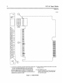
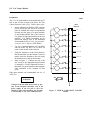
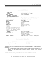
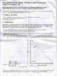
Series Six Plus
Programmable
Controller
115 VAC Input Module
32 Inputs per Module
GFK-0174
March 1988
and a Schmitt trigger (one-shot), which fires to indicate that an AC voltage in a specified range has been
detected. An active input circuit is indicated by a
Light-Emitting Diode (LED), visible through a lens
on the faceplate.
General Description
The 115 VAC Input module detects bipolar AC voltage supplied by, and controlled by, the user. The
features and benefits of this module are summarized
in Table 1.
Refer to Table 2 for the I15 VAC Input module
specifications.
A module contains thirty two inputs, divided into four
groups (A, B, C, D), each group sharing a neutral
circuit (A corn, B corn, C corn or D corn).
An input circuit contains an AC divider, a noise filter
to reduce common mode transients, an opto-isolator,
Table 1. FEATURES AND BENEFITS
FEATURES
I- ~~
I
I
I
Useful in a variety of applications.
High Density Input:
115 VAC 47 Hz.- 63 Hz.
I
Allows visual inspection of I/O operations.
Alpha numeric LED for each input (on logic
side)/Color-coded
faceplate.
Efficient use of I/O rack space with flexibility in multiple
I common applications.
Provides electrical isolation between user power supplies
I and Series Six Plus Programmable Controller.
APPLICATIONS
*Monitor:
*Proximity Switches
*CamSwitches
*Relays
Thirty two inputs per module in four isolated groups of
eight.
Optically-coupled inputs.
*Limit Switches
*Toggle Switches
BENEFITS
115 VAC Input Module
3
GFK-0174
InstalIation
a42382
The 115 VAC Input module can be installed in an I/O
rack or the I/O rack section of the Series Six Plus
Central Processor Unit (CPU). Follow these steps:
1.
I
I
I
Set the Dual-In-Line-Package (DIP) switches
directly behind the card slot on the rack backplane to establish the correct correspondence
between the first group of 8 input terminals
on this module and the first of four consecutive groups of eight input numbers in the user
program. For further information on I/O
DIP-switch settings, refer to the Installation
Section of the Series Six Plus Programmable
Controller User’s Manual (GEK-96602).
2.
Use the extraction/insertion tool furnished
with the Series Six Plus CPU to insert (or
remove) this module in the card slot.
3.
Guide the faceplate over the circuit board so
that the terminals near the bottom of each are
mated; secure the faceplate to the rack using
the thumbscrews at the top and bottom.
4.
Refer to Figure 2. Connect one side of the
user circuit to the appropriate input terminal
(1 through 8). Circuits connected to inputs 1
through 8 of a group must have their opposite
sides connected to the common for that
group.
1
2
INPUT
MODULE
-
a - -
I - -
Each input terminal can accommodate one No. 12
AWG wire.
*AC SOURCE
A, f3, C OR D
WARNING
I
Voltages from user field devices may be present on the faceplate terminals, even if the
power supply in the I/O rack is off. Care
should be taken when handling the faceplate
of this module or any wires connected to it.
Figure 2. TYPICAL USER INPUT CONNEC
TIONS
115 VAC Input Module
4
GFK-OI74
Table 2. SPECIFICATIONS
Dimensions:
Circuit Board:
Faceplate:
Power Requirements:
Supplied by
I/Opower supply.
The user must supply power for the
input devices.
Number of Inputs:
Operating Temperature:
Storage Temperature:
Humidity:
On Range:
Off Range:
Input Current:
(Typical)
ON Delay:
OFF Delay:
Isolation (any group common to Series Six
Plus common - also between input groups
when two or more independent user power
supplies are used for one module):
Continuous:
Transient:
Noise Immunity to:
Radiated Interference:
8.15 x 11.0 (inches) 208 x 280 (mm)
12.46 x 1.175 (inches) 317 x 30 (mm)
5V DC, 104 ma maximum
Thirty-two (32) in four groups (A, B, C, D) of 8 inputs (l-8)
with independent common, neutral connections.
0” to 60” (At the outside of rack)
-20 to +8O”C
5 to 95% (non-condensing)
80-132VAC
0-30VAC
9.8 ma @ 115 VAC, 50 Hz.
11.7 ma @ 115 VAC, 60 Hz.
l0-20 ms
20-40 ms
240 VDC or 50/60 Hz. AC
1,500 V peak, non-repetitive
Showering arcs per NEMA ICS 2.230.40
Surges per ANSI C37.90.9
5W transmitter, 27-450 MHz
Complies with FCC Rule 15 for Class A computing devices
Table 3, ORDERING INFORMATION
DESCRIPTION
Circuit Board and Faceplate
Faceplate
CATALOG NUMBER
IC600BF832K
IC600FP832K
The equipment listed above having the catalog number shown is designed for listing by UL for use as an auxiliary
control device.
The UL symbol on the nameplate means the product is listed by Underwriters Laboratories Inc. (UL
Standard No. 508, Industrial Control Equipment, subsection Electronic Power Conversion
Equipment.)
For further information, contact your local GE Fanuc North America Distributor or sales office.
GE Fanuc Automation North America, Inc., Charlottesville, Virginia