1
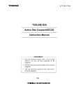
Manual: Lens Driver 4
Date: 09.07.2014
Copyright © 2014 Optotune
Electrical Lens Driver 4
Lens Driver Manual
Page 1 of 20
No representation or warranty, either expressed or implied, is made
W W W.asStoT the
E Mreliability,
M E R- Icompleteness
M A G I N Gor. accuracy
C O M of this paper.
Optotune AG | Bernstrasse 388 | CH-8953 Dietikon | Switzerland
Phone +41 58 856 3000 | www.optotune.com | [email protected]
Manual: Lens Driver 4
Date: 09.07.2014
Copyright © 2014 Optotune
Table of Contents
1.
2.
3.
4.
5.
Overview ......................................................................................................................................................... 3
1.1
Integration into OEM systems ............................................................................................................... 3
1.2
System requirements ............................................................................................................................ 3
Hardware Operation ....................................................................................................................................... 4
2.1
Connecting the EL-10-30-C .................................................................................................................... 4
2.2
Connecting the EL-10-30-C to the lens driver with an extension cable ................................................. 4
2.3
Connecting the EL-10-30 compact to the lens driver ............................................................................ 4
2.4
Connecting the EL-10-30-Ci to the lens driver ....................................................................................... 4
2.5
Open and close housing of Lens Driver 4i.............................................................................................. 5
2.6
Connector Pinout ................................................................................................................................... 6
Lens Driver Controller Software ...................................................................................................................... 7
3.1
Software Installation ............................................................................................................................. 7
3.2
Installation of the Windows driver in Windows XP and Windows 7 ..................................................... 7
3.3
Installation of the Windows driver in Windows 8.1 .............................................................................. 7
Operating Lens Driver Controller .................................................................................................................... 7
4.1
Controls ................................................................................................................................................. 7
4.2
Limiting the maximum current .............................................................................................................. 8
4.3
Temperature compensation .................................................................................................................. 8
4.4
Achievable Range of Focal Power .......................................................................................................... 9
4.5
Drift Compensation ............................................................................................................................. 10
4.6
Autofocus ............................................................................................................................................ 11
4.7
Trigger output signal............................................................................................................................ 12
4.8
Analog Signal Reading ......................................................................................................................... 13
4.9
Sensor Control ..................................................................................................................................... 13
Communication Protocol .............................................................................................................................. 14
5.1
Current set commands ........................................................................................................................ 14
5.2
Focal Power set command .................................................................................................................. 15
5.3
Mode commands ................................................................................................................................. 16
5.4
Calibration commands ......................................................................................................................... 17
5.5
Temperature reading ........................................................................................................................... 18
5.6
CRC algorithm ...................................................................................................................................... 18
5.7
Checking for communication error ...................................................................................................... 18
5.8
Adding a CRC checksum to a data array .............................................................................................. 19
Page 2 of 20
No representation or warranty, either expressed or implied, is made
as to the reliability, completeness or accuracy of this paper.
W W W. S T E M M E R- I M A G I N G . C O M
Optotune AG | Bernstrasse 388 | CH-8953 Dietikon | Switzerland
Phone +41 58 856 3000 | www.optotune.com | [email protected]
Manual: Lens Driver 4
Date: 09.07.2014
Copyright © 2014 Optotune
1. Overview
The Electrical Lens Driver offers a simple yet precise way to control Optotune’s electrical lenses. There are two
types of lens drivers available. The Electrical Lens Driver 4 is used to drive the EL-6-18 and EL-10-30-C lens series and comes in a plastic housing. The second Lens Driver 4i is suited to drive the EL-10-30-Ci industrial version and is contained in a steel housing. Both drivers can be used as a standalone solution or integrated into
OEM designs. The main features are:
x
x
x
x
x
x
Current control range up to -290 to +290 mA with 12 bit precision
Drive frequencies from 0.2 to 2000 Hz (rectangular, triangular or sinusoidal)
I2C sensor read-out e.g. for temperature compensation
USB powered
Driver software in Windows 7 and Windows 8
Available with or without housing
Mechanical specifications
Lens Driver 4
Lens Driver 4i
Dimensions (L x W x H)
77 x 19 x 13
99.05 x 19 x 13.5
mm
Weight
11
41
g
Interface to lens
0.5mm pitch 6 way FPC connector
6-pin Hirose connector
Interface to PC
Electrical specifications
USB Type A
Lens Driver 4
Maximum output current
Up to 290mA, depending on resistance (see Figure 8)
Drive current range for EL-6-18
-290 to +290
mA
Drive current range for EL-10-30-C, -Ci
-200 to +200
mA
>100
kHz
Maximum output update frequency
USB input voltage
5
Power consumption
Thermal specifications
mW
12 bit Analog Devices ADN8810
Microcontroller
Connector
V
50-1100
Digital to analog converter
1.1
Lens Driver 4i
8-bit, 16 MHz with 32 KB Flash (Atmel ATmega32U4)
6-way FPC (Molex 503480-0600)
Lens Driver 4
6-way Hirose HR 10 G
Lens Driver 4i
Operating temperature
-20 to +65
°C
Storage temperature
-40 to +85
°C
Integration into OEM systems
Both Lens Drivers are easily integrated into OEM systems. The microcontroller that is used offers serial interfaces over USB, RS-232 or SPI. Also, analog input from 0-5V is available. Schematics and part list of the Lens
Drivers are available on request. Documentation of the firmware is presented at the end of this document. For
more information please contact [email protected].
1.2
System requirements
x Windows 7 or Windows 8.1, 32/64 bit
x Lens driver: USB 2.0 port
x uEye camera: USB 2.0 port (preferably 3.0)
Page 3 of 20
No representation or warranty, either expressed or implied, is made
as to the reliability, completeness or accuracy of this paper.
W W W. S T E M M E R- I M A G I N G . C O M
Optotune AG | Bernstrasse 388 | CH-8953 Dietikon | Switzerland
Phone +41 58 856 3000 | www.optotune.com | [email protected]
Manual: Lens Driver 4
Date: 09.07.2014
Copyright © 2014 Optotune
2. Hardware Operation
2.1
Connecting the EL-10-30-C
The Molex flex cable of the EL-10-30-C lens can be plugged directly into the connector of the lens driver. The
copper side of the cable has to be upwards and the black clamp has to be closed.
Figure 1: Connecting the EL-10-30-C directly to the lens driver.
2.2
Connecting the EL-10-30-C to the lens driver with an extension cable
If a larger distance is required, the easiest way is to use an USB extension cable for the lens driver. If a larger
distance in between the lens and the driver is required, an extension as described in Figure 2 can be built. For
2
large distances, shielded cables are recommended to ensure interference-free performance of the I C bus. The
butterfly connector and the 5cm long transition cable are provided with the lens driver.
butterfly connector
transition cable
Figure 2: Connecting the EL-10-30-C with an extension cable to the lens driver.
2.3
Connecting the EL-10-30 compact to the lens driver
The 30cm long cables of the EL-10-30 compact can be directly soldered to the lens driver. The plus and minus
poles are indicated in the figure below.
+
Figure 3: Connecting the compact EL-10-30 to the lens driver by soldering the plus and minus poles.
2.4
Connecting the EL-10-30-Ci to the lens driver
The connection of the industrial EL-10-30-Ci to the Lens Driver 4i is straight forward. Simply connect the cable
to the plug, the position of the pins is unambiguous.
Page 4 of 20
No representation or warranty, either expressed or implied, is made
as to the reliability, completeness or accuracy of this paper.
W W W. S T E M M E R- I M A G I N G . C O M
Optotune AG | Bernstrasse 388 | CH-8953 Dietikon | Switzerland
Phone +41 58 856 3000 | www.optotune.com | [email protected]
Manual: Lens Driver 4
Date: 09.07.2014
Copyright © 2014 Optotune
2.5
Open and close housing of Lens Driver 4i
To open the housing use the gaps on the side to spread the cover side-walls with an appropriate flat head
screw driver. Hold the enclosure base and lift the cover to open the casing:
In order to close the housing, place the cover on top of the enclosure base (a) and move it towards the USB
stick (b) until the front side clips fit in the openings of the cover. Then push the cover at the back downwards
(c) until the back side clips snap into the square holes (d). If the clips do not snap in, gently apply pressure from
the top/bottom/side to move the cover forward/backward or up/down relative to the base unit.
Page 5 of 20
No representation or warranty, either expressed or implied, is made
as to the reliability, completeness or accuracy of this paper.
W W W. S T E M M E R- I M A G I N G . C O M
Optotune AG | Bernstrasse 388 | CH-8953 Dietikon | Switzerland
Phone +41 58 856 3000 | www.optotune.com | [email protected]
Manual: Lens Driver 4
Date: 09.07.2014
Copyright © 2014 Optotune
2.6
Connector Pinout
Figure 4: Connector pinout of the Lens Driver 4 (left) and Lens Driver 4i (right).
Position
1
2
3
4
5
6
Lens Driver 4
Function
I2C Gnd
Lens (- pole)
Lens (+ pole)
I2C SDA
I2C SCL
I2C Vcc 3.3V
Lens Driver 4i
Position
1
2
3
4
5
6
Function
Lens (+ pole)
Lens (- pole)
I2C Gnd
I2C Vcc 3.3V
I2C SCL
I2C SDA
Page 6 of 20
No representation or warranty, either expressed or implied, is made
as to the reliability, completeness or accuracy of this paper.
W W W. S T E M M E R- I M A G I N G . C O M
Optotune AG | Bernstrasse 388 | CH-8953 Dietikon | Switzerland
Phone +41 58 856 3000 | www.optotune.com | [email protected]
Manual: Lens Driver 4
Date: 09.07.2014
Copyright © 2014 Optotune
3. Lens Driver Controller Software
3.1
Software Installation
x
x
3.2
Run Setup.exe
Follow the installation wizard
Installation of the Windows driver in Windows XP and Windows 7
x
3.3
Start Lens Driver Controller. Should the Windows driver not yet be installed, you will be shown a window describing a detailed installation procedure.
Installation of the Windows driver in Windows 8.1
x
x
x
x
x
x
x
x
x
x
Installation of the Windows driver in Windows 8.1 requires disabling the driver signature enforcement
first. The following steps explain this procedure.
Press the Win + C keyboard combination to bring up the charms bar, then click on the Settings charm.
Click on Change PC settings.
In Control Panel, click on Update and recovery.
Now click on Recovery.
On the right hand side in the Advanced Startup section click on Restart now.
Once your computer has rebooted click on Troubleshoot.
Now click on Advanced Options, then Startup Settings and finally Restart.
Your computer will now restart again and show you a list of options. Select option 7) Disable driver
signature enforcement by pressing F7 on your keyboard.
Your computer will now restart with driver signature enforcement disabled and you may continue
with the normal driver installation procedure. In order to do so, start Lens Driver Controller. Should
the Windows driver not yet be installed, you will be shown a window describing a detailed installation
procedure.
4. Operating Lens Driver Controller
Launch Optotune Lens Driver Controller and click on Connect. This will establish the hardware connection and
open the main window with the current control and the temperature readout.
4.1
Controls
Figure 5 shows the main window. The output current can be changed, either by shifting the arrow or by using
the +/- buttons. Using the +/- buttons together with the Shift key increases the step size. Alternatively, the
desired value can be written in the gray box.
Figure 5: Screenshot of the main window of the Lens Driver software with the current control.
The drive signal can be chosen to be a DC, sinusoidal, rectangular or triangular signal with the possibility to set
the upper and the lower signal level as well as the driving frequency. This is indicated in Figure 6.
Page 7 of 20
No representation or warranty, either expressed or implied, is made
as to the reliability, completeness or accuracy of this paper.
W W W. S T E M M E R- I M A G I N G . C O M
Optotune AG | Bernstrasse 388 | CH-8953 Dietikon | Switzerland
Phone +41 58 856 3000 | www.optotune.com | [email protected]
Manual: Lens Driver 4
Date: 09.07.2014
Copyright © 2014 Optotune
Figure 6: The drive signal can be chosen to be a DC, sinusoidal, rectangular or triangular signal.
4.2
Limiting the maximum current
The limits for the current are set in the Hardware tab, shown in Figure 7.
Figure 7: Setting the current limits.
The maximum current of the driver is limited to either 290mA, see Figure 8, or 2.8V divided by the resistance
applied.
300.0
Maximum current
250.0
200.0
150.0
100.0
50.0
0.0
0
5
10
15
20
25
30
Coil resistance
Figure 8: Dependence of maximum current on coil resistance.
4.3
Temperature compensation
When heating up the lens, the fluid expands in volume and therefore, the focal length of the lens decreases.
The focal length decreases linearly by approximately 0.67 diopters per 10°C temperature increase. This temperature effect is systematic and reproducible and is therefore accurately compensated via a temperature
Page 8 of 20
No representation or warranty, either expressed or implied, is made
as to the reliability, completeness or accuracy of this paper.
W W W. S T E M M E R- I M A G I N G . C O M
Optotune AG | Bernstrasse 388 | CH-8953 Dietikon | Switzerland
Phone +41 58 856 3000 | www.optotune.com | [email protected]
Manual: Lens Driver 4
Date: 09.07.2014
Copyright © 2014 Optotune
2
sensor SE97B with an I C sensor read-out, integrated in the lens (not in the compact EL-10-30). This allows
controlling the focal power directly.
In Focal Power mode, see drop down menu in Figure 6, temperature independent lens operation is ensured.
Depending on the present temperature, the current applied to the lens is adjusted for compensation of the
temperature drift. A look-up table with the calibration data for the temperature compensation are stored directly on the EEPROM of each individual lens. With the temperature compensation enabled, the absolute reproducibility achieved over an operating temperature range of 10 to 50°C amounts to typically 0.1 diopters.
4.4
Achievable Range of Focal Power
If the focal power is outside the guaranteed diopter range then a warning message will appear in yellow “warning focal power outside guaranteed range” and the panel has a yellow background, see Figure 9. The user can
then change the focal power until the displayed focal power no longer has a yellow color and is within the
guaranteed diopter range.
Figure 9: On the left, the focal power is outside the guaranteed range and the panel is yellow. On the right, the
focal power is within the range.
The limits for the range of focal power are determined by the temperature limits and the maximum and minimum current. The maximum diopter limit is located at highest encoded temperature limit and maximum current and the minimum diopter limit is located at the lowest encoded temperature and the minimum current.
This is explained in Figure 10. The highest and lowest temperature define a sector for the linear relation of focal
power versus current, indicated by the light and dark gray line. The values are adjustable in File Æ Options
under Temperature Settings. The colored line represents the diopter range at the current temperature between the highest and lowest temperature, with the colors representing the following states:
x
x
x
Green: Focal power can successfully be maintained at predefined temperatures limits in this range.
Yellow: Focal power can be maintained at the current temperature and/or current drift state.
Red: Focal power cannot be maintained at the current temperature and/or drift state.
The minimum green/yellow limit is determined by the diopter value at the highest temperature and minimum
current. The maximum green/yellow limit is determined by the diopter value at the lowest temperature and
maximum current. Both limits are indicated by the dashed horizontal lines in Figure 10. The closer together the
minimum and maximum temperature limits are, the larger the guaranteed range (green) will be. In addition,
the yellow/red limits are determined by the diopter values at min/max current at the current temperature.
Page 9 of 20
No representation or warranty, either expressed or implied, is made
as to the reliability, completeness or accuracy of this paper.
W W W. S T E M M E R- I M A G I N G . C O M
Optotune AG | Bernstrasse 388 | CH-8953 Dietikon | Switzerland
Phone +41 58 856 3000 | www.optotune.com | [email protected]
Manual: Lens Driver 4
Date: 09.07.2014
Copyright © 2014 Optotune
Highest Temperature
Lowest Temperature
Focal Power (m-1)
Dioptermax
Diopter
pter Range
Dioptermin
Currentmin
Current (mA)
Currentmax
Figure 10: Illustration of the achievable range of focal power (vertical axis) versus current (horizontal axis). The
guaranteed range (green line) also depends on the highest and lowest temperature, indicated by the gray lines.
4.5
Drift Compensation
When set to a certain focal power the lens shows a tiny drift over timescales of about 5min. If a highly stable
focus position over long times is required, using the implemented drift compensation is recommended. To do
so the Drift Compensation Gain, found under Hardware (see Figure 7) has to be set by the user to a finite value,
typically 1, otherwise no compensation is taking place. Higher values increase the gain up to a maximum value
of 5. Internally, two parameters Driftmax and Driftcurrent are affected by the Drift Compensation Gain, as discussed in the following.
When finite drift compensation is set it also scales the achievable diopter range. Figure 11 illustrates the effect
that drift compensation will have on the achievable diopter range. First, compared to Figure 10, the yellow/red
boundaries in Figure 11 are shifted upwards due to a finite current drift (Driftcurrent). As a consequence the
achievable diopter range is also shifted upwards by a small amount. Second, the maximum drift Driftmax set by
the drift compensation is added to the minimum guaranteed diopter limit, which is represented by the lower
yellow/green boundary, and therefore slightly reduces the guaranteed diopter range. The maximum drift is
determined by the gain variable and a larger gain variable will result in a larger maximum drift.
For lenses with a small focal range the effect of increasing the gain variable to high values (e.g. 3 or higher) can
be that the achievable diopter range is too small such that focal power cannot anymore be changed by the
user. In that case the gain variable has to be reduced.
A visual representation of the overall achievable focal power range as shown on the focal power scroll bar in
the software can be found in Figure 12.
Page 10 of 20
No representation or warranty, either expressed or implied, is made
as to the reliability, completeness or accuracy of this paper.
W W W. S T E M M E R- I M A G I N G . C O M
Optotune AG | Bernstrasse 388 | CH-8953 Dietikon | Switzerland
Phone +41 58 856 3000 | www.optotune.com | [email protected]
Manual: Lens Driver 4
Date: 09.07.2014
Copyright © 2014 Optotune
Highest Temperature
Lowest Temperature
Dioptermax
Driftcurrent
Focal Power (m-1)
Diopter Range
ge
Driftmax
Driftcurrent
Dioptermin
Currentmin
Current (mA)
Currentmax
Figure 11: Illustration how drift compensation affects the achievable range of focal power.
Figure 12: Overall achievable diopter range as shown on the focal power scroll bar.
4.6
Autofocus
When using the Lens Driver in combination with a uEye camera, it also offers an autofocus feature. Please note
that this feature is for testing purposes only and Optotune does not offer support for this part of the software.
The autofocus software is only tested yet with the camera model IDS UI-3580CP-C-HQ. To use the autofocus, go
to Extras → uEye Viewer. The uEye viewer window will open.
Settings:
In Lens driver → Auto Focus Settings, the settings can be adjusted to optimize the autofocusing. The parameter
shown in Figure 13 are standard values that work for most applications. In order to optimize e.g. the time it
takes to autofocus one may set the thresholds for coarse, mid and fine scanning closer to 1, but the values
have to be Coarse < Mid < Fine. The check box to enable auto switch to focal power acts only if a lens with
Page 11 of 20
No representation or warranty, either expressed or implied, is made
as to the reliability, completeness or accuracy of this paper.
W W W. S T E M M E R- I M A G I N G . C O M
Optotune AG | Bernstrasse 388 | CH-8953 Dietikon | Switzerland
Phone +41 58 856 3000 | www.optotune.com | [email protected]
Manual: Lens Driver 4
Date: 09.07.2014
Copyright © 2014 Optotune
stored calibration data on the lens’s EEPROM is used. Camera settings like frame rate and exposure time can be
changed in Camera → Settings. Autofocus only works reliably if the image is bright enough.
Figure 13: Settings for the Auto Focus option in combination with a uEye camera.
For autofocus, click on the image in an area that contains structures with reasonable contrast. The current
applied to the lens is then automatically adjusted and the image is in focus, as in Figure 14.
Figure 14: Autofocus is achieved by clicking on the image
Options:
enables maximal camera resolution
auto exposure
auto whitebalance
pixel-to-pixel
zoom
switch modus
Pixel-to-pixel modus: in the ‘pixel-to-pixel’ modus, the resolution is chosen in the way that one pixel of the
image corresponds to one pixel of the screen.
Switch modus: In this modus, the driver switches between two current values with a rectangular driving signal.
The lower and upper current level can be determined in the following way. First perform autofocusing for the
lower level (click on the part of the image which should be in focus) and afterwards click on the lower limit
button (arrow with an underline). Repeat the steps for the upper limit (arrow with an over line). If you than
enable the button with the two arrows, the current will switch between the two values. The frequency is
changed in the Controls window.
4.7
Trigger output signal
For sinusoidal, triangular and rectangular drive signals, hardware pin A (see Figure 15) outputs a trigger signal
which can be used to synchronize the lens driver to another hardware component. The synchronization output
signal toggles between 0 V and 5 V and provides a maximum of 15 mA. Please note that the pin “Analog In A”
has been re-configured from an analog input to a digital output (trigger output).
Page 12 of 20
No representation or warranty, either expressed or implied, is made
as to the reliability, completeness or accuracy of this paper.
W W W. S T E M M E R- I M A G I N G . C O M
Optotune AG | Bernstrasse 388 | CH-8953 Dietikon | Switzerland
Phone +41 58 856 3000 | www.optotune.com | [email protected]
Manual: Lens Driver 4
Date: 09.07.2014
Copyright © 2014 Optotune
Figure 15: Hardware pin A for trigger output signal.
The relation between the trigger output signal and the corresponding output signal of the Lens Driver for different drive signals are shown in Figure 16:
Figure 16: Relation between trigger and output signal for different drive signals.
4.8
Analog Signal Reading
Analog signal reading is built into the firmware, hardware pin B (see Figure 17). The analog voltage of the input
signal must be between 0 V and 5 V. The ADC has a resolution of 10 bit and therefore the digital signal lies
between 0 and 1023.
Figure 17: Hardware pin B for analog input signal.
4.9
Sensor Control
Through an analog signal that is read by the lens driver, an external voltage from an analog sensor can be used
to control the focal power of the lens. Sensor control can be used in either Current or Focal Power
mode, and is enabled under Services -> Sensor
Control.
To enable this functionality, a set of calibration
points must first be inputted. A calibration point
consists of an analog input value set by a sensor and
a desired current/focal power value. If sensor control is enabled, the software will linearly interpolate
between the configured points, and set the current/focal power according to the analog input. It is
important to note that sensor control will only be
enabled if at least two calibration points have been
defined. Calibration points can be stored using the
sensor control configuration form found under ExPage 13 of 20
No representation or warranty, either expressed or implied, is made
as to the reliability, completeness or accuracy of this paper.
W W W. S T E M M E R- I M A G I N G . C O M
Optotune AG | Bernstrasse 388 | CH-8953 Dietikon | Switzerland
Phone +41 58 856 3000 | www.optotune.com | [email protected]
Manual: Lens Driver 4
Date: 09.07.2014
Copyright © 2014 Optotune
tras -> Sensor Control Configuration. The points are stored in a modifiable table, and are saved in the software
for future use. The screenshot below represents the sensor configuration form in Current mode.
Button Functions:
x
x
x
x
Record Entry: Store the latest analog input and current/focal power value as a calibration point.
Add Row: Create an empty row in the configuration table to manually input a calibration point.
Delete Row: Every row with a highlighted cell will be removed from the table.
Save Table: Save the configuration table. Note that sensor control will only work if at least two calibration points have been saved.
Quit: Exit the sensor control configuration form. Users will be prompted to save any unsaved data.
x
5. Communication Protocol
This section describes the protocol used to control the lens driver in case customized software is written. The
protocol can be implemented using any programming language. An example for the CRC calculation is only
given in C.
The documentation shows commands sent out by user software (i.e. PC) and the answer to be expected as a
response from the driver as well as the action that is taken by the driver as a result of the command. Commands in quotes (“) have to be sent as a string (or char array) with each letter representing one byte except for
“\r” meaning “carriage return”, “\n” meaning “new line” and are represented by a single byte (ASCII code).
Letters in red are sent as ASCII characters and letters in blue are coded as binary bytes.
While this section describes the protocol for the main commands used to control the lens driver, detailed information on other commands can be found in the command protocol file which is available as a download on
our website.
Connection:
The Microcontroller used runs a virtual com port driver provided by Atmel. The connection settings are:
x
Baudrate: 115200 (others may also work since the port is virtual)
x Parity: None
x Stop Bits: One
Handshake:
The handshake command is used to check if the hardware is ready and running. It can also be used as a reset
function as it will reset the current to zero. Other commands are also valid without sending this command after
initialization, it is optional.
PC sends
Driver answer
Driver action
Comment
"Start"
"Ready\r\n"
reset current to zero, flush input buffer
optional command
5.1
Current set commands
A current set command sets a new output current for a channel. A current set command is constructed as
1
AwxxLH. It always starts with the channel identifier "A" for channel A , and the write identifier char “w”. The
current sent out (io) is coded as a 12bit value (xi) that is mapped to the maximum hardware current range (ic).
The maximum hardware current range (calibration value i c) can be read and written from the driver, see section about calibration commands. By default, i c = 293mA. The formula to calculate the value x i for a certain
current is:
xi = io / ic * 4096
Example for a current of 50mA for a calibration value of 293mA:
50mA / 293mA * 4096 = 699
1
Currently, the Lens Driver only hosts one channel. In future, a second channel might be added to control two lenses simultaneously.
Page 14 of 20
No representation or warranty, either expressed or implied, is made
as to the reliability, completeness or accuracy of this paper.
W W W. S T E M M E R- I M A G I N G . C O M
Optotune AG | Bernstrasse 388 | CH-8953 Dietikon | Switzerland
Phone +41 58 856 3000 | www.optotune.com | [email protected]
Manual: Lens Driver 4
Date: 09.07.2014
Copyright © 2014 Optotune
Commands to set current are sent as one char selecting the channel, followed by two bytes containing the
16bit signed current value xi [-4096 to 4096], followed by two bytes for the CRC16 checksum which is calculated over all the preceding data bytes (see CRC16 code section on how to implement it) with the low byte of the
CRC sent first: “LH” means ‘Low Byte’, ‘High Byte’. If a value is out of boundaries (i.e. 5000) it is limited to 4096
by the firmware, no overflow will occur. If the software current limit is set lower than 4096 (i.e. 3000, see calibration commands), current requests bigger than the software limit will be reduced down to the limit (i.e.
3000). The driver does not reply to correctly received current commands to make the possible update rate as
fast as possible. Invalid commands (i.e. incorrect CRC) will be answered with “N\r\n”.
Char coding for the current set command:
"A"
Channel A
“w”
Write Identifier
PC sends
Driver answer
Driver action
"AwxxLH"
none
set channel
current to xx
"AwxxLf"
"N\r\n"
none
Comment
A
xx is a signed 16bit integer with a value between -4096 and 4096, high
byte sent first
f = error in CRC byte, this line applies for all detected CRC errors.
Exemplary current set command
Command type: Set current
Channel: A
Current value: 1202
Resulting command:
Byte 0: 0x41 (corresponds to ASCII "A")
Byte 1: 0x77 (corresponds to ASCII "w")
Byte 2: 0x04 (high current byte) / 0b00000100
Byte 3: 0xb2 (low current byte) / 0b10110010 -> with byte 2 the total current bits are
0b0000010010110010 which equals to 1202 dec
Byte 4: 0x26 (low CRC byte)
Byte 5: 0x93 (high CRC byte)
For verification of the command, the CRC checksum (see details below) over the whole 6 bytes of the command
can be calculated which should be zero.
5.2
Focal Power set command
A focal power set command sets the focal power of the lens. The command starts with the prefix “P”, followed
by the write identifier “w”, the coding char “D”, and the channel identifier “A”. The command then includes 2
bytes for the desired focal power value and 2 dummy bytes. Focal power is encoded with the following formula
to have an effective range of -5 to 15.48 diopters:
xi = (fp +5) *200
Example for a focal power of 5 diopters:
(5 + 5) * 200 = 2000
Similar to current set commands, the command is finished by a 16bit CRC calculated from the eight command
bytes. The low byte of the CRC is sent first. It is important to note that this command will only work in controlled mode (see Mode Commands below).
Char coding for the focal power set command:
Page 15 of 20
No representation or warranty, either expressed or implied, is made
as to the reliability, completeness or accuracy of this paper.
W W W. S T E M M E R- I M A G I N G . C O M
Optotune AG | Bernstrasse 388 | CH-8953 Dietikon | Switzerland
Phone +41 58 856 3000 | www.optotune.com | [email protected]
Manual: Lens Driver 4
Date: 09.07.2014
Copyright © 2014 Optotune
"P"
Prefix
“w”
Write Identifier
“D”
Coding
"A"
Channel A
PC sends
Driver answer
Driver action
Comment
"PwDAxxYYLH"
none
set focal power of
lens
through
channel A
xx is a signed 16bit integer with a value between 0 and 4096, high byte
sent first. YY are 16 dummy bits.
" PwDAxxYYLf "
"N\r\n"
none
f = error in CRC byte, this line applies for all detected CRC errors.
Exemplary focal power set command
Command type: Set focal power
Channel: A
Focal power value: 2000 (5 diopters)
Resulting command:
Byte 0: 0x50 (corresponds to ASCII "P")
Byte 1: 0x77 (corresponds to ASCII "w")
Byte 2: 0x44 (corresponds to ASCII "D")
Byte 3: 0x41 (corresponds to ASCII "A")
Byte 4: 0x07 (high focal power byte) / 0b00000111
Byte 5: 0xd0 (low focal power byte) / 0b11010000 -> with byte 1 the total current bits are 0b
0000011111010000 which equals to 2000 dec
Byte 6: 0x00 (required dummy byte)
Byte 7: 0x00 (required dummy byte)
Byte 8: 0x31 (low CRC byte)
Byte 9: 0xfd (high CRC byte)
5.3
Mode commands
Mode commands allow to access frequency modes (see table). A mode change command always starts with
"M", followed by a "w" to write the command. Reading commands back is by sending an “r” instead of a “w” is
possible but not tested and recommended. The “w” is followed by a char identifier that selects the mode type
(“S”, “Q”, “T”,”C” or “D”, see table) and finally a char selecting the channel (“A”). The command is finished by a
16bit CRC calculated from the four command bytes. The low byte of the CRC is sent first.
To set the property of the selected mode (i.e. frequency and currents) a signal property change command is
used. This command starts with a “P” followed by a “w” to write the command. Again, reading commands back
is by sending an “r” instead of a “w” is possible but not tested and recommended. The “w” is followed by a char
identifier that selects the property to be changed (“U”, “L” or “F”, see table). Next a char selecting the channel
(“A”) is sent. The next four bytes sent represent the data for the command. It is a 32-bit unsigned integer for
the frequency or a 16bit signed integer followed by two dummy bytes for the current. The frequency needs to
be multiplied by 1000 (fixed comma representation). Example: For a frequency of 12Hz the integer sent out
needs to be 12000 (0x00002EE0 as a 32bit hex). The bytes to be sent out (in this order) are: 0x00, 0x00, 0x2E,
0xE0. The command is finished by a 16bit CRC calculated from the eight command bytes. The low byte of the
CRC is sent first.
The mode “C”, or Controlled Mode, allows the driver to maintain the focal power of a connected lens. This
mode must be enabled in order to use focal power set commands.
Char coding for the mode change command:
Page 16 of 20
No representation or warranty, either expressed or implied, is made
as to the reliability, completeness or accuracy of this paper.
W W W. S T E M M E R- I M A G I N G . C O M
Optotune AG | Bernstrasse 388 | CH-8953 Dietikon | Switzerland
Phone +41 58 856 3000 | www.optotune.com | [email protected]
Manual: Lens Driver 4
Date: 09.07.2014
Copyright © 2014 Optotune
"A"
Channel A
“w”
Write Identifier
"S"
Sinusoidal signal
"Q"
Square signal
"D"
DC signal
"T"
Triangular signal
“C”
Controlled Mode
Char coding for the signal property change command:
"U"
upper swing current [-4095 to 4095]
"L"
lower swing current [-4095 to 4095]
"F"
Frequency (in ‘value in [mHz] = value in [Hz] *1000’ )
Mode command examples:
PC sends
Driver answer
Driver action
“MwSALH”
"MSALH\r\n"
set channel A to sinusoidal waveform
“MwCALH”
"MCALH\r\n"
set channel A to controlled mode
„PwFAyyyyLH“
nothing
set channel A frequency to yyyy (in mHz, 32bit value)
„PwUAyyddLH“
nothing
set channel A upper signal current to yy (12 bit value)
(dd are two dummy stuffing bytes and can be 0)
5.4
Calibration commands
Calibration commands are used to set and read calibration values and software current limits. These values are
stored in the EEPROM, a non-volatile memory, and are kept there for years.
Software current limits can be set to protect a lens from overcurrent or to fix the maximum focal power. Limits
also apply in analog input mode.
Note: in analog input mode the input voltage 0-5V is mapped to [-4095 to 4095] in a 10bit resolution.
Software current limits apply.
A calibration command always starts with "C" followed by "r" to road or "w" to write the command value. The
next byte determines the type of value. It can be “M” for the maximum current calibration value (in [mA*100]),
“U” for the upper software current limit or “L” for the lower software current limit. Next a char selecting the
channel (“A”) is sent followed by two data bytes (16-bit integer). The maximum current calibration value is the
output current measured for the xi = 4095 value and does normally not need to be changed as design guarantees 1% accuracy to the default value. The default value is 29284 (292.84mA).The software current limits are
sent as a 12bit current value and can also be negative like a normal current command. As usual the command is
finished by a 16bit CRC calculated over the seven command bytes.
Note: the upper and lower limits are always saved to EEPROM that allows "only" 100'000 write cycles
before it starts wearing out. There is no limit on reading.
Char coding for the Calibration command:
"A"
Channel A
"M"
Maximum hardware current [mA]*100 (calibration value)
"U"
Upper software current limit [-4095 to 4095]
"L"
Lower software current limit [-4095 to 4095]
Page 17 of 20
No representation or warranty, either expressed or implied, is made
as to the reliability, completeness or accuracy of this paper.
W W W. S T E M M E R- I M A G I N G . C O M
Optotune AG | Bernstrasse 388 | CH-8953 Dietikon | Switzerland
Phone +41 58 856 3000 | www.optotune.com | [email protected]
Manual: Lens Driver 4
Date: 09.07.2014
Copyright © 2014 Optotune
Calibration command examples:
PC sends
Driver answer
Driver action
Comment
"CrMAddLH"
"CMAyyLH\r\n"
none
read channel A calibration, "dd" are two dummy bytes and can be 0
"CwLAxxLH"
"CLAxxLH\r\n"
write xx as new lower
limit of channel A
limit is immediately active, answer is for double checking
"CrUAddLH"
"CUAyyLH\r\n"
none
read channel A upper current limit, "dd" are two dummy bytes and can be
0
5.5
Temperature reading
If the lens connected supports temperature reading, this command will read back the temperature of the integrated sensor (NXP SE97B). To convert the value to a temperature the following formula can be used:
Temperature [°C] = data * 0.0625 [°C]
For more details about the conversion please refer to the datasheet of the temperature sensor.
The temperature read command starts with a “T” followed by the channel selection byte (“A”). The command
is completed with the 16bit CRC calculated over the two command bytes. Low CRC byte is sent first.
Possible temperature commands:
PC sends
Driver answer
Driver action
Comment
“TALH”
“TAEddLH\r\n”
Get temperature reading
of lens on channel A
E is 0x00 if read is successful, 0xff otherwise. “dd” is the temperature
data.
5.6
CRC algorithm
A 16-bit CRC checksum (CRC-16-IBM) is used to check for communication errors. The code examples below use
the reverse polynomial implementation.
x
x
5.7
Reverse polynomial: 0xA001
Initial value to be used: 0x0000
Checking for communication error
Checking for a communication error is done by calculating the CRC checksum over the whole command data
array which includes two CRC bytes at the end that were added from the sender. CRC checksum calculation
over the whole array results in a CRC checksum equal to zero if no data corruption is present.
The following example shows the checkcrc implementation in the Lens Driver firmware, which is written in C:
/* Example usage of the CRC function */
// Example:
Set current level to 1202 command sent from PC (includes CRC bytes)
//
With this data array the returned uint16_t crc checksum will be zero
//
(0x00) since no communication error has occurred.
//
uint8_t data[] = { 0x41, 0x77, 0x04, 0xb2, 0x26, 0x93 };
uint16_t calculatecrc(void)
{
uint16_t crc = 0, i;
for (i = 0; i < sizeof(data) / sizeof(data[0]); i++)
{
crc = crc16_update(crc, data[i]);
}
return crc; //returns checksum over all elements
}
uint16_t crc16_update(uint16_t crc, uint8_t a)
{
int i;
crc ^= a;
Page 18 of 20
No representation or warranty, either expressed or implied, is made
as to the reliability, completeness or accuracy of this paper.
W W W. S T E M M E R- I M A G I N G . C O M
Optotune AG | Bernstrasse 388 | CH-8953 Dietikon | Switzerland
Phone +41 58 856 3000 | www.optotune.com | [email protected]
Manual: Lens Driver 4
Date: 09.07.2014
Copyright © 2014 Optotune
}
5.8
for (i = 0; i < 8; ++i)
{
if (crc & 1)
crc = (crc >> 1) ^ 0xA001;
else
crc = (crc >> 1);
}
return crc;
Adding a CRC checksum to a data array
In order to add a CRC checksum to a data array
1.
2.
Calculate CRC checksum over data array
Append the calculated CRC checksum at the end of the data array
Example:
uint8_t dataarray[3] = {data byte 0, data byte 1, data byte 2}
uint8_t dataarraywithcrc[5] = { data byte 0, data byte 1, data byte 2, crc&0xFF,
crc>>8}
If this is done correctly, a consecutive CRC checksum calculation over the whole array needs to result in a CRC
checksum equal to zero (see method AddAndCheckCRC).
The following example written in c# shows the implementation in the Lens Driver Controller software:
private byte[] AddAndCheckCRC(byte[] command)
{
UInt16 CRC = 0;
byte[] commandWithCRC = new byte[command.Length + 2];
CRC16IBM CRC16IBMCalculator = new CRC16IBM();
CRC = CRC16IBMCalculator.ComputeChecksum(command);
Array.Copy(command, 0, commandWithCRC, 0, command.Length);
commandWithCRC[commandWithCRC.Length - 2] = (byte)(CRC&0xFF);
commandWithCRC[commandWithCRC.Length - 1] = (byte)(CRC >> 8);
//Check if calculation is correct (should equal 0)
check = CRC16IBMCalculator.ComputeChecksum(commandWithCRC);
}
return commandWithCRC;
public class CRC16IBM
{
const ushort polynomial = 0xA001;
ushort[] table = new ushort[256];
public ushort ComputeChecksum(byte[] bytes)
{
ushort crc = 0; // initial CRC value
for (int i = 0; i < bytes.Length; ++i)
{
byte index = (byte)(crc ^ bytes[i]);
crc = (ushort)((crc >> 8) ^ table[index]);
}
return crc;
}
public byte[] ComputeChecksumBytes(byte[] bytes)
{
ushort crc = ComputeChecksum(bytes);
return BitConverter.GetBytes(crc);
}
public CRC16IBM()
Page 19 of 20
No representation or warranty, either expressed or implied, is made
as to the reliability, completeness or accuracy of this paper.
W W W. S T E M M E R- I M A G I N G . C O M
Optotune AG | Bernstrasse 388 | CH-8953 Dietikon | Switzerland
Phone +41 58 856 3000 | www.optotune.com | [email protected]
Manual: Lens Driver 4
Date: 09.07.2014
Copyright © 2014 Optotune
{
}
ushort value;
ushort temp;
for(ushort i = 0; i < table.Length; ++i) {
value = 0;
temp = i;
for(byte j = 0; j < 8; ++j) {
if(((value ^ temp) & 0x0001) != 0) {
value = (ushort)((value >> 1) ^ polynomial);
}else {
value >>= 1;
}
temp >>= 1;
}
table[i] = value;
}
O-OPTU6-06/2015 ∙ Subject to technical change without notice. No liability is accepted for errors which may be contained in this document.
}
Page 20 of 20
No representation or warranty, either expressed or implied, is made
Optotune AG | Bernstrasse 388 | CH-8953 Dietikon | Switzerland
as to the reliability, completeness or accuracy of this paper.
Phone +41 58 856 3000 | www.optotune.com | [email protected]
STEMMER
IMAGI
NG
Head
Office
Imaging is our passion.
Gutenbergstraße 9 - 13, D-82178 Puchheim
W W W. S T E M M E R- I M A G I N G . C O MPhone: +49 89 80902-0, [email protected]
www.stemmer-imaging.com