1
GE
Sensing & Inspection Technologies
Remote Visual Inspection
Everest XLG3™ VideoProbe® System
Software Version 2.0
Operating Manual
g
Everest XLG3™
VideoProbe System
®
Operating Manual
ii
GE Inspection Technologies XLG3 VideoProbe System
Copyright 2009 GE Inspection Technologies, LP. All rights are reserved. No one is permitted to reproduce or duplicate, in any form,
this manual or any part thereof without permission from GE Inspection Technologies, LP.
Software in this product is copyright GE Inspection Technologies, LP, or its vendors. All rights are reserved. The software is protected
by United States of America copyright and international treaty provisions applicable worldwide. Under such laws, the licensee is
entitled to use the copy of the software incorporated with this instrument as intended in the operation of the product in which it is
embedded. The software may not be copied, decompiled, reverse-engineered, disassembled, or otherwise reduced to humanperceivable form. This is not a sale of the software or any copy of the software; all right, title, and ownership of the software remains
with GE Inspection Technologies, LP, or its vendors.
VideoProbe, ShadowProbe, and StereoProbe are registered trademarks of GE Inspection Technologies, LP. XL PRO, XLG3, iView,
All-Way, QuickChange, and Steer-and-Stay are trademarks of GE Inspection Technologies, LP.
NETGEAR is a registered trademark of NETGEAR, Inc. Firefox is a registered trademark of the Mozilla Foundation.
MPEG Layer-3 audio coding technology licensed from Fraunhofer IIS and Thomson.
GE Inspection Technologies, LP, assumes no responsibility for any injury to anyone, or for any illegal or improper use of the product,
that may result from failure to use this product in accordance with the information published in this manual.
This device complies with Part 15 of the FCC Rules. Operation is subject to the following two conditions: (1) this device may not
cause harmful interference, and (2) this device must accept any interference received, including interference that may cause
undesired operation
FCC Statement
This product has been tested and complies with the specifications for a Class B digital device, pursuant to Part 15 of FCC Rules.
These limits are designed to provide reasonable protection against harmful interference in a residential installation. This equipment
generates, uses, and can radiate radio frequency energy and, if not installed and used according to the instructions, may cause
harmful interference to radio communications. However, there is no guarantee that interference will not occur in a particular
installation. If this equipment does cause harmful interference to radio television reception, which is found by turning the equipment
off and on, the user is encouraged to try to correct the interference by one or more of the following measures:
• Reorient or relocate the receiving antenna
• Increase the separation between the equipment or devices
• Connect the equipment to an outlet other than the receiver's
• Consult a dealer or an experienced radio/lV technician for assistance
FCC Radiation Exposure Statement
This equipment complies with FCC radiation exposure limits set forth for an uncontrolled environment. This equipment should be
installed and operated with minimum distance 20 cm between the radiator and your body.
Safety Notices
Caution: To reduce the risk of fire, use only No.26 AWG or larger telecommunication line cord.
Do not use this product near water, for example. in a wet basement or near a swimming pool.
User Manual
iii
Contact Information
Service
To obtain service for your system, call one of the service centers below. If the problem
cannot be corrected over the phone, you will be given a Return Materials Authorization
Number (RMA) for shipment to the service center.
Always contact a GE Inspection Technologies service center for an RMA prior to returning
any products for service or repair.
USA
GE Inspection Technologies
Product Service Dept.
721 Visions Drive
Skaneateles, NY 13152
Phone: 888-332-3848
315-554-2000 ext. 1
Fax:
866 899 4184
Germany
GE Inspection Technologies GmbH
Lotzenäcker 4
72379 Hechingen
Phone: +49 7471 98820
Fax:
+49 7471 9882 30
Hong Kong
GE Inspection Technologies (HK) Ltd.
Unit 1602, 16/F Sing Pao Building
101 King's Road
North Point
Hong Kong
Phone: +852 2877 0801
Fax:
+852 2877 0868
Web Site
www.ge.com/inspectiontechnologies
iv
GE Inspection Technologies XLG3 VideoProbe System
v
Contents
Contact Information . . . . . . . . . . . . . . . . . . . . . . . . . . . . . . . . . . . . . . . iii
1 - Introduction . . . . . . . . . . . . . . . . . . . . . . . . . . . . . . . . . . . . . . . . . . . . . 1
About This Manual . . . . . . . . . . . . . . . . . . . . . . . . . . . . . . . . . . . . . . . . . . . . . . . . 1
Getting Help . . . . . . . . . . . . . . . . . . . . . . . . . . . . . . . . . . . . . . . . . . . . . . . . . . . . . 1
System Overview . . . . . . . . . . . . . . . . . . . . . . . . . . . . . . . . . . . . . . . . . . . . . . . . . 2
Frequent Tasks . . . . . . . . . . . . . . . . . . . . . . . . . . . . . . . . . . . . . . . . . . . . . . . . . . . 3
About the Battery . . . . . . . . . . . . . . . . . . . . . . . . . . . . . . . . . . . . . . . . . . . . . . . . . 4
About the Image Processing Package . . . . . . . . . . . . . . . . . . . . . . . . . . . . . . . . . 4
About the Network Package . . . . . . . . . . . . . . . . . . . . . . . . . . . . . . . . . . . . . . . . . 5
About the Menu Directed Inspection Package . . . . . . . . . . . . . . . . . . . . . . . . . . . 6
Controls, Indicators, Connectors, etc.. . . . . . . . . . . . . . . . . . . . . . . . . . . . . . . . . . 7
Navigating the Menus . . . . . . . . . . . . . . . . . . . . . . . . . . . . . . . . . . . . . . . . . . . . . 15
Restoring Factory Defaults . . . . . . . . . . . . . . . . . . . . . . . . . . . . . . . . . . . . . . . . . 16
Safety Information. . . . . . . . . . . . . . . . . . . . . . . . . . . . . . . . . . . . . . . . . . . . . . . . 17
Informations sur la sécurité. . . . . . . . . . . . . . . . . . . . . . . . . . . . . . . . . . . . . . . . . 20
2 - Safe Powering and Grounding. . . . . . . . . . . . . . . . . . . . . . . . . . . . . 23
Overview of Safe Powering and Grounding . . . . . . . . . . . . . . . . . . . . . . . . . . . .
Verifying AC Earth Ground Path . . . . . . . . . . . . . . . . . . . . . . . . . . . . . . . . . . . . .
Grounding With a DC Source (Battery) . . . . . . . . . . . . . . . . . . . . . . . . . . . . . . .
Special Grounding Situations . . . . . . . . . . . . . . . . . . . . . . . . . . . . . . . . . . . . . . .
23
24
25
25
3 - Setting Up and Putting Away the System. . . . . . . . . . . . . . . . . . . . 27
Setting Up the System . . . . . . . . . . . . . . . . . . . . . . . . . . . . . . . . . . . . . . . . . . . . 27
Changing the Probe . . . . . . . . . . . . . . . . . . . . . . . . . . . . . . . . . . . . . . . . . . . . . . 30
Changing the Optical Tip . . . . . . . . . . . . . . . . . . . . . . . . . . . . . . . . . . . . . . . . . . 31
Putting the System Away . . . . . . . . . . . . . . . . . . . . . . . . . . . . . . . . . . . . . . . . . . 32
Communicating to a PC Through a Router or Network . . . . . . . . . . . . . . . . . . . 34
Manual Entry - Wireless Access Point . . . . . . . . . . . . . . . . . . . . . . . . . . . . . . . . 37
4 - Setting Up the Software . . . . . . . . . . . . . . . . . . . . . . . . . . . . . . . . . . 39
Reviewing Settings for Audio . . . . . . . . . . . . . . . . . . . . . . . . . . . . . . . . . . . . . . .
Reviewing Settings for Image Format and Quality . . . . . . . . . . . . . . . . . . . . . . .
Reviewing the Setting for Video Quality . . . . . . . . . . . . . . . . . . . . . . . . . . . . . . .
Reviewing Settings for Text Color. . . . . . . . . . . . . . . . . . . . . . . . . . . . . . . . . . . .
Reviewing Settings for a Logo . . . . . . . . . . . . . . . . . . . . . . . . . . . . . . . . . . . . . .
Reviewing Settings for Measurement . . . . . . . . . . . . . . . . . . . . . . . . . . . . . . . . .
Reviewing Settings for the System . . . . . . . . . . . . . . . . . . . . . . . . . . . . . . . . . . .
Reviewing Settings for Communications . . . . . . . . . . . . . . . . . . . . . . . . . . . . . .
39
40
41
42
42
43
44
45
vi
GE Inspection Technologies XLG3 VideoProbe System
5 - Capturing Images and Videos . . . . . . . . . . . . . . . . . . . . . . . . . . . . . 47
Process Overview. . . . . . . . . . . . . . . . . . . . . . . . . . . . . . . . . . . . . . . . . . . . . . . . 47
Steering the Probe . . . . . . . . . . . . . . . . . . . . . . . . . . . . . . . . . . . . . . . . . . . . . . . 49
Freezing an Image . . . . . . . . . . . . . . . . . . . . . . . . . . . . . . . . . . . . . . . . . . . . . . . 50
Working With a Recalled Image . . . . . . . . . . . . . . . . . . . . . . . . . . . . . . . . . . . . . 51
Working With a Split Screen . . . . . . . . . . . . . . . . . . . . . . . . . . . . . . . . . . . . . . . . 52
Adjusting the Brightness . . . . . . . . . . . . . . . . . . . . . . . . . . . . . . . . . . . . . . . . . . . 53
Reducing “Noise” in Dark Images. . . . . . . . . . . . . . . . . . . . . . . . . . . . . . . . . . . . 54
Correcting Wide-Angle Distortion . . . . . . . . . . . . . . . . . . . . . . . . . . . . . . . . . . . . 56
Lengthening Exposure Time . . . . . . . . . . . . . . . . . . . . . . . . . . . . . . . . . . . . . . . . 57
Enhancing Contrast . . . . . . . . . . . . . . . . . . . . . . . . . . . . . . . . . . . . . . . . . . . . . . 58
Zooming . . . . . . . . . . . . . . . . . . . . . . . . . . . . . . . . . . . . . . . . . . . . . . . . . . . . . . . 58
Inverting an Image . . . . . . . . . . . . . . . . . . . . . . . . . . . . . . . . . . . . . . . . . . . . . . . 59
Annotating With Text or Arrows . . . . . . . . . . . . . . . . . . . . . . . . . . . . . . . . . . . . . 60
Saving an Image. . . . . . . . . . . . . . . . . . . . . . . . . . . . . . . . . . . . . . . . . . . . . . . . . 65
Working With Videos . . . . . . . . . . . . . . . . . . . . . . . . . . . . . . . . . . . . . . . . . . . . . 67
6 - Managing Files & Communicating With Other Computers . . . . . . 73
About the Thumbnail Screen . . . . . . . . . . . . . . . . . . . . . . . . . . . . . . . . . . . . . . . 73
Working With Removable Storage Devices . . . . . . . . . . . . . . . . . . . . . . . . . . . . 74
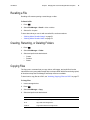
Recalling a File . . . . . . . . . . . . . . . . . . . . . . . . . . . . . . . . . . . . . . . . . . . . . . . . . . 75
Creating, Renaming, or Deleting Folders . . . . . . . . . . . . . . . . . . . . . . . . . . . . . . 75
Copying Files . . . . . . . . . . . . . . . . . . . . . . . . . . . . . . . . . . . . . . . . . . . . . . . . . . . 75
Deleting Files . . . . . . . . . . . . . . . . . . . . . . . . . . . . . . . . . . . . . . . . . . . . . . . . . . . 76
Renaming a File . . . . . . . . . . . . . . . . . . . . . . . . . . . . . . . . . . . . . . . . . . . . . . . . . 76
Archiving (Copying) Files to a DVD . . . . . . . . . . . . . . . . . . . . . . . . . . . . . . . . . . 77
Using the Desktop . . . . . . . . . . . . . . . . . . . . . . . . . . . . . . . . . . . . . . . . . . . . . . . 78
Sharing Files or Live Video With a PC . . . . . . . . . . . . . . . . . . . . . . . . . . . . . . . . 80
7 - Measuring Features and Defects. . . . . . . . . . . . . . . . . . . . . . . . . . . 87
About Measuring. . . . . . . . . . . . . . . . . . . . . . . . . . . . . . . . . . . . . . . . . . . . . . . . . 87
Stereo Measurements. . . . . . . . . . . . . . . . . . . . . . . . . . . . . . . . . . . . . . . . . . . . . 90
Shadow Measurements . . . . . . . . . . . . . . . . . . . . . . . . . . . . . . . . . . . . . . . . . . . 98
Comparison Measurements . . . . . . . . . . . . . . . . . . . . . . . . . . . . . . . . . . . . . . . 104
Verifying Measurement Tips . . . . . . . . . . . . . . . . . . . . . . . . . . . . . . . . . . . . . . . 106
Troubleshooting Measurements . . . . . . . . . . . . . . . . . . . . . . . . . . . . . . . . . . . . 107
8 - Maintenance . . . . . . . . . . . . . . . . . . . . . . . . . . . . . . . . . . . . . . . . . . 109
Inspecting and Cleaning the System . . . . . . . . . . . . . . . . . . . . . . . . . . . . . . . . 109
Replacing the Lamp . . . . . . . . . . . . . . . . . . . . . . . . . . . . . . . . . . . . . . . . . . . . . 112
Checking and Replacing the Fuses . . . . . . . . . . . . . . . . . . . . . . . . . . . . . . . . . 114
Maintaining the Battery . . . . . . . . . . . . . . . . . . . . . . . . . . . . . . . . . . . . . . . . . . . 116
Replacing the Internal Memory Card . . . . . . . . . . . . . . . . . . . . . . . . . . . . . . . . 119
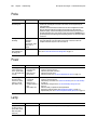
9 - Troubleshooting . . . . . . . . . . . . . . . . . . . . . . . . . . . . . . . . . . . . . . . 121
Image . . . . . . . . . . . . . . . . . . . . . . . . . . . . . . . . . . . . . . . . . . . . . . . . . . . . . . . .
Probe . . . . . . . . . . . . . . . . . . . . . . . . . . . . . . . . . . . . . . . . . . . . . . . . . . . . . . . .
Power . . . . . . . . . . . . . . . . . . . . . . . . . . . . . . . . . . . . . . . . . . . . . . . . . . . . . . . .
Lamp. . . . . . . . . . . . . . . . . . . . . . . . . . . . . . . . . . . . . . . . . . . . . . . . . . . . . . . . .
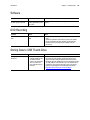
Software . . . . . . . . . . . . . . . . . . . . . . . . . . . . . . . . . . . . . . . . . . . . . . . . . . . . . .
DVD Recording. . . . . . . . . . . . . . . . . . . . . . . . . . . . . . . . . . . . . . . . . . . . . . . . .
121
122
122
122
123
123
User Manual
vii
Storing Data to USB Thumb Drive . . . . . . . . . . . . . . . . . . . . . . . . . . . . . . . . . . 123
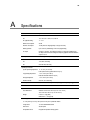
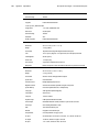
A - Specifications . . . . . . . . . . . . . . . . . . . . . . . . . . . . . . . . . . . . . . . . . 125
B - Agency Certifications. . . . . . . . . . . . . . . . . . . . . . . . . . . . . . . . . . . 129
C - Chemical Compatibility . . . . . . . . . . . . . . . . . . . . . . . . . . . . . . . . . 131
D - Warranty . . . . . . . . . . . . . . . . . . . . . . . . . . . . . . . . . . . . . . . . . . . . . 133
E - Menu Trees . . . . . . . . . . . . . . . . . . . . . . . . . . . . . . . . . . . . . . . . . . . 135
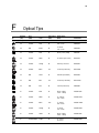
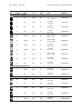
F - Optical Tips . . . . . . . . . . . . . . . . . . . . . . . . . . . . . . . . . . . . . . . . . . . 141
G - Environmental Compliance . . . . . . . . . . . . . . . . . . . . . . . . . . . . . . 145
Index . . . . . . . . . . . . . . . . . . . . . . . . . . . . . . . . . . . . . . . . . . . . . . . . . . . 147
viii
GE Inspection Technologies XLG3 VideoProbe System
1
1
Introduction
About This Manual. . . . . . . . . . . . . . . . . . . . . . . . . . . . . . . . . . . . . . . . . . . . . . . . . 1
Getting Help. . . . . . . . . . . . . . . . . . . . . . . . . . . . . . . . . . . . . . . . . . . . . . . . . . . . . . 1
System Overview. . . . . . . . . . . . . . . . . . . . . . . . . . . . . . . . . . . . . . . . . . . . . . . . . . 2
Frequent Tasks . . . . . . . . . . . . . . . . . . . . . . . . . . . . . . . . . . . . . . . . . . . . . . . . . . . 3
About the Battery . . . . . . . . . . . . . . . . . . . . . . . . . . . . . . . . . . . . . . . . . . . . . . . . . . 4
About the Image Processing Package . . . . . . . . . . . . . . . . . . . . . . . . . . . . . . . . . 4
About the Network Package . . . . . . . . . . . . . . . . . . . . . . . . . . . . . . . . . . . . . . . . . 5
About the Menu Directed Inspection Package . . . . . . . . . . . . . . . . . . . . . . . . . . . 6
Controls, Indicators, Connectors, etc. . . . . . . . . . . . . . . . . . . . . . . . . . . . . . . . . . . 7
Navigating the Menus . . . . . . . . . . . . . . . . . . . . . . . . . . . . . . . . . . . . . . . . . . . . . 15
Safety Information . . . . . . . . . . . . . . . . . . . . . . . . . . . . . . . . . . . . . . . . . . . . . . . . 16
Informations sur la sécurité . . . . . . . . . . . . . . . . . . . . . . . . . . . . . . . . . . . . . . . . . 19
About This Manual
This manual is written for visual inspection technicians who have a basic understanding of
inspection principles and practices, and who are familiar with basic computer operations
(such as using a mouse and managing electronic files and folders), but who may not have
experience with a video borescope.
The manual provides a product overview, step-by-step procedures, and reference
information. It does not include repair information.
To ensure operator safety, read and understand this manual before using the system.
Getting Help
Beyond this manual you can get product help in several ways:
•
Training
Introductory in-person training is free with your system purchase. Additional training is
available for a fee. Contact GE Inspection Technologies.
•
Phone
For phone numbers, see “Service” on page iii.
2
Chapter 1 Introduction
GE Inspection Technologies XLG3 VideoProbe System
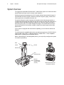
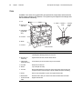
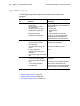
System Overview
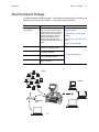
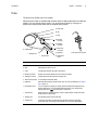
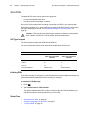
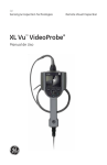
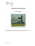
The rugged and dependable Everest XLG3™ VideoProbe® system is an advanced videobased flexible borescope used for remote visual inspection.
Working through access passages, the XLG3 system delivers high-resolution images of
internal details of turbine engines, airframes, automotive engines, piping, vessels, windturbine gear boxes, underwater structures, etc.
The probe’s fiberoptic bundle illuminates the inspection area with light generated by a
75-watt high-intensity discharge (HID) arc lamp in the base unit. At the end of the probe, a
miniature camera assembly converts the image into an electronic image, and sends it
back through the probe. The system displays the image on the handset. No focusing is
required, because the XLG3 system contains a fixed-focus optical system with a large
depth of field.
If your system is equipped with measurement capability, you can measure defects and
features.
The XLG3 system is compatible with various removable storage devices: DVD-R, DVD+R,
compact Flash cards (Type 1), USB thumb drives, portable drives — most compatible
USB-based or compact Flash card-based devices.
With our QuickChange™ interchangeable probes, you can quickly reconfigure the system
for maximum productivity.
GE
Inspection Technologies
Probe
Everest XLG3
Camera
Handset
Remote control
Everest XLG3
Case
(small size shown)
Base unit
(accessible when
case door is open,
as shown)
Base unit removed from case:
two positions for handset
User Manual
Chapter 1 Introduction
Frequent Tasks
Setting Up the System — Summary
For details, see “Setting Up the System” on page 27.
1. Open case’s lids and front door.
2. Verify safe powering and grounding.
Inspect ground prong on power cord.
3. Connect to AC power, or attach battery.
4. Turn on power switch.
5. Remove insertion tube from storage reel.
6. Unwrap handset cable, and remove handset from case.
7. Install optical tip, accessories, and peripheral devices.
Capturing Images — Summary
For details, see “Capturing Images and Videos” on page 47.
1. Steer probe until desired view is displayed.
Position camera by moving joystick toward desired feature.
2. Freeze the image.
When desired image is displayed, press
.
3. Save the image.
Press
. Select Return. The image is saved.
Recording Video — Summary
For details, see “Working With Videos” on page 67.
1. Start recording video.
Press . Select Start Recording.
2. Stop recording video.
Press
. Select Video Record > Stop Recording.
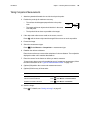
Putting the System Away — Summary
For details, see “Putting the System Away” on page 32.
1.
2.
3.
4.
5.
Straighten bending neck.
Turn off system, and disconnect from power source.
Detach peripheral devices and accessories.
Return insertion tube to storage reel, and wrap handset cable.
Store system and components in case.
3
4
Chapter 1 Introduction
GE Inspection Technologies XLG3 VideoProbe System
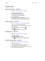
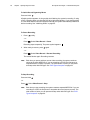
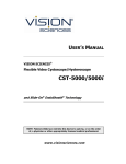
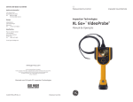
About the Battery
Batteries for the XLG3 system are optional. Two sizes are available: one-hour and
two-hour.
To learn about removing, charging, or installing the battery, see “Maintaining the Battery”
on page 116.
Battery (one-hour size shown)
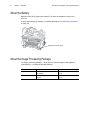
About the Image Processing Package
The image processing package — which lets you enhance images under particular
circumstances — includes the following features.
Feature
Description
Details
Distortion correction
Flattens image edges when you use a
120° optical tip.
“Correcting Wide-Angle Distortion” on
page 56
Adaptive noise reduction
Sharpens images when the probe is in a
dark area.
“Reducing “Noise” in Dark Images” on
page 54
User Manual
Chapter 1 Introduction
5
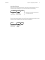
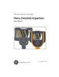
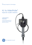
About the Network Package
The optional network software package — which delivers communication, file sharing, and
network functions for the XLG3 system — includes the following features.
Feature
Description
Details
PC and network
communications
You can communicate between the XLG3
system and a PC via a wired or wireless
network connection. Then you can browse
the XLG3 system from the PC and view,
download, or upload files. You can also
view live video from the PC (“video
streaming”). Note: The XLG3 system
cannot be connected directly to a PC. See
page 34.
“Communicating to a PC Through a Router
or Network” on page 34
“Reviewing Settings for Communications”
on page 45
“Sharing Files or Live Video With a PC” on
page 80
“To Save an Image” on page 66
Virtual desktop
You can manage files and access other
applications via a graphical interface.
Internet browsing
You can access web pages for viewing,
downloading, or uploading.
E-mail
You can access any outside e-mail service
to send e-mail with files attached.
Internal WiFi
A built-in wireless card lets you connect to a
wireless access point.
“Using the Desktop” on page 78
Internet
Network
Wired/Wireless
Router
PC
6
Chapter 1 Introduction
GE Inspection Technologies XLG3 VideoProbe System
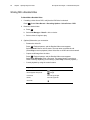
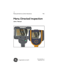
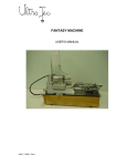
About the Menu Directed Inspection Package
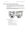
Menu Directed Inspection (MDI) is the first software tool to standardize the inspection
process in the NDT industry. MDI software helps guide inspectors through the inspection
process and intelligently auto-generates a report—saving time, improving quality and
increasing productivity.
Menu Directed Inspection (MDI) software provides an advantage and convenience during
the inspection process. MDI makes labeling images and videos easier and automatically
generates reports from the VideoProbe within a few steps.
SYSTEM TOOLS
SYSTEM INFO
MDI
POWER MANAGEMENT
SYSTEM TOOLS
SYSTEM INFO
MDI
POWER MANAGEMENT
UNLOAD
ANNOTATE
LOAD
UNLOAD
ANNOTATE
BACK
SELECT
Benefits to using MDI include:
•
Standardized Inspection Lists.
•
Consistent Report Creation in MS Word format
•
Data Management
•
Decreased reporting time by up to 70%
•
Increased speed and ease of sharing data
•
Reduction of errors with guided inspections
LOAD
User Manual
Chapter 1 Introduction
Controls, Indicators, Connectors, etc.
This section describes the controls, indicators, connectors, and other key elements for
each main system component:
•
•
•
•
•
“Handset” on page 7
“Control Buttons” on page 8
“Probe” on page 9
“Base Unit” on page 10
“Case” on page 14
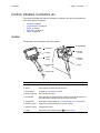
Handset
The handset is your interface to the XLG3 system.
hnolog
F. Flashlight LEDs
A. Microphone
ies
Tec
GE
ection
Insp
B. Display
G. Electrical
connector
C. Control
buttons
H. Fiberoptic
connector
D. Shoulder-strap
loops
I. Trigger
G3
st XL
Evere
E. Handset cable
Item
Description
A. Microphone
Lets you record voice comments for video or still images.
B. Display
Large, bright, high-resolution wide-VGA LCD screen.
C. Control buttons
For details, see “Control Buttons” on page 8.
D. Shoulder-strap loops
Strap is an optional accessory.
E. Handset cable
Plugs into the base unit. Powers the handset, enables communication with the base unit,
and conducts light via a fiberoptic bundle from the lamp to the handset.
F. Flashlight LEDs
Provide light for reading or writing. See “To Turn the Flashlight On and Off” on page 29.
G. Electrical connector
Enables communication between base unit, handset, and probe.
H. Fiberoptic connector
Couples light to the probe.
I. Trigger
Same functions as the freeze/enter button
(item B. on page 8).
7
8
Chapter 1 Introduction
GE Inspection Technologies XLG3 VideoProbe System
Control Buttons
The control buttons are conveniently located directly below the handset display. The same
controls are available on the optional remote control.
Remote
Control
(Optional)
Handset
Everest XLG3
Everest XLG3
A. Record
H. Save
B. Freeze/enter
G. Exit/back
F. Menu
C. Zoom
E. Joystick
D. Home &
Steer-and-Stay
Item
Description
A. Record
Starts and pauses video recording. See “Working With Videos” on page 67.
B. Freeze/enter
Performs same functions as the trigger (item I. on page 7).
• Freezes and unfreezes images.
• Selects highlighted items.
• One-click report (see “Menu-Directed Mode”)
C. Zoom
Changes the zoom level. See “Zooming” on page 58.
D. Home &
Steer-and-Stay
Performs two functions:
• Home (press and hold). See “To Straighten the Bending Neck (HOME)” on page 49.
• Steer-and-Stay (press quickly). See “To Hold the Bending Neck in Place
(Steer-and-Stay Mode)” on page 49.
E. Joystick
Moves the probe tip, pans around zoomed images, moves through menus, and navigates
the desktop.
F. Menu
Opens and exits menus. See “Navigating the Menus” on page 15.
G. Exit/back
Exits a menu or operation.
H. Save
Opens the save menu. See “Saving an Image” on page 65.
I. Restore factory
Restores factory defaults for system settings. See “Restoring Factory Defaults” on page 16.
defaults
+
(5 seconds)
User Manual
Chapter 1 Introduction
9
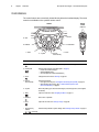
Probe
The probe is the flexible eye of the system.
Various probe models are available with insertion tubes of different diameters and different
lengths. You can change probes quickly. You can also travel lighter by carrying one
system and a spare probe rather than a complete spare system.
A. Strain relief
B. Clip
C. Latch
D. Electrical
connector
E. Fiberoptic
connector
F. Motor shaft
connectors
K. Insertion tube
G. Optical tip
J. Bending neck
I. Camera head
Probe inserted into handset
H. Temperature
sensor
Item
Description
A. Strain relief
Allows the insertion tube to twist up to 180 degrees in either direction.
B. Clip
Holds probe end when not in use.
C. Latch
C-shaped piece that locks the probe in the handset.
D. Electrical connector
Enables communication between base unit, handset, and probe.
E. Fiberoptic connector
Couples light from the handset into the insertion tube.
F. Motor shaft connectors For controlling the articulation cables.
G. Optical tip
Removable part containing unique precision optics. For a list of available tips, see “Optical
Tips” on page 141.
H. Temperature sensor
For 6.1 mm probes only. Displays a warning symbol and beeps when temperature at the
probe tip approaches or exceeds operating temperature limits. For an example of the
warning symbol, press
, and select Setup > Temp Sensor.
I. Camera head
Made of titanium for superior protection. Contains a high-resolution, durable camera that
provides clear, true-color images.
J. Bending neck
The articulating section of the insertion tube.
K. Insertion tube
A woven tube of tungsten wire that protects the electrical conductors and the lighttransmission fibers. Conducts light to the inspection area, and returns digital images.
10
Chapter 1 Introduction
GE Inspection Technologies XLG3 VideoProbe System
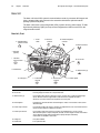
Base Unit
The base unit is the XLG3 system’s communications center. It processes still images and
video, manages data, and connects to the external world with the optional network
package (via the front panel).
The base unit houses a processing board (CPU), system memory, power supply, 75-watt
high-intensity discharge (HID) arc lamp, and an integrated reel that can store even the
longest insertion tubes.
Base Unit, Front
K. Headset/external
speaker connector
L. Power
switch
M. Audio out
connector
N. External microphone
connector
A. Ethernet connector
J. DVD drive
(optional)
I. VGA video
output connector
B. CF card slot
H. Air filter frame
G. Cooling fans
C. USB connectors (3)
F. S-video input
connector
E. S-video output
connector
D. Internal speaker
Item
Description
A. Ethernet connector
For connecting to a network or to the Internet with the optional network package.
B. CF card slot
For saving images and videos onto a compact Flash card.
C. USB connectors (3)
For connecting various devices: a keyboard, a mouse, a memory stick, or other removable storage
devices. All three connectors support USB 2.0 data rates and are compatible with USB 1.1
devices.You can connect or disconnect a keyboard or mouse any time.
D. Internal speaker
For playback of comments that were saved with images or videos. The menu-driven volume control
affects this output.
E. S-video output connector
For connecting a cable to the “video in” connector of a peripheral device, such as an external monitor or
recorder. S-video cables are available as accessories.
F. S-video input connector
For connecting a cable to the “video out” connector of a peripheral device, such as a camera.
Allows the XLG3 system to capture, manipulate, annotate, and store images and videos from external
sources. When the system detects external input, it displays that input automatically.
S-video cables are available as accessories.
G. Cooling fans
For system ventilation.
H. Air filter frame
For an optional air filter.
User Manual
Chapter 1 Introduction
11
Item (cont.)
Description (cont.)
I. VGA video output connector
For connecting a PC-type monitor.
J. DVD drive (optional)
For storing video files.
K. Headset/external speaker
connector
3.5 mm phone jack for a standard stereo headset or an external speaker. The menu-driven volume
control affects this output. If headset is plugged in, the internal speaker is automatically disabled.
L. Power switch
Turns the system on and off.
M. Audio out connector
3.5 mm phone jack for a recording device (VCR, digital video tape recorder, etc.), or for powered
speakers with their own volume control. Transmits line-level output signals (~2V RMS max). The menudriven volume control does not affect this output.
N. External microphone connector
3.5 mm phone jack for a headset microphone or standalone microphone. An external microphone has
the same function as the built-in microphone. When an external microphone is plugged in, the system
automatically uses it for audio recording rather than the built-in microphone.
12
Chapter 1 Introduction
GE Inspection Technologies XLG3 VideoProbe System
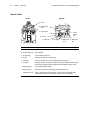
Base Unit, Sides
Right Side
Left Side
A. Funnel
B. Shoulder-strap
hooks
C. AC power inlet
I. Internal
memory
card
D. AC fuse
E. Ground lug
F. AC output
G. Battery (DC) H. Battery (DC)
input
fuse
Item
Description
A. Funnel
Guides the insertion tube into the storage reel.
B. Shoulder-strap hooks
Strap is included.
C. AC power inlet
For connecting the power cord.
D. AC fuse
Protects the circuitry when using AC power.
E. Ground lug
Provides an earth ground if one is not available through the AC outlet.
F. AC output
IEC-type F connector. The voltage and frequency of the power available at the AC output is
the same as the voltage and frequency applied to the inlet. Maximum output is 100 W.
G. Battery (DC) input
For connecting a battery (optional).
H. Battery (DC) fuse
Protects the circuitry when using a battery or other DC power source.
I. Internal memory card
Card is in the drive behind the access panel. This card contains the operating system
software and the memory for storing images. This card is not user serviceable.
User Manual
Chapter 1 Introduction
Base Unit, Top and Bottom
Top
Bottom
E. Battery connection
points
A. Funnel
B. Socket for handset
holder
C. Power switch
D. Shoulder-strap
hooks
F. Lamp
Item
Description
A. Funnel
Guides the insertion tube into the storage reel.
B. Socket for handset holder
Supports the handset holder.
C. Power switch
Turns the system on and off.
D. Shoulder-strap hooks
Strap is an optional accessory.
E. Battery connection points
For holding the optional battery in place. The bracket is part of the battery assembly.
F. Lamp
High-intensity discharge (HID) arc lamp, behind access panel.
Base Unit, Back
A. Handset power plug
B. Lock screw ring
C. Pocket
Item
Description
A. Handset power plug
Connects the handset cable to the base unit.
B. Lock screw ring
Latch that disconnects the power plug.
C. Pocket
Mesh storage pocket.
13
14
Chapter 1 Introduction
GE Inspection Technologies XLG3 VideoProbe System
Case
Available in two sizes, the rugged XLG3 case protects the components and accessories
during storage, shipping, and operation. The system may be shipped in the storage case
without additional overboxing.
A. Lids
G. Handle
B. Rear latch (not
visible here)
H. Release I. Socket for
handset
button
holder
C. Lifting handles
(top and both
sides)
D. Front latch
E. Wheels
F. Front door
Small size shown
Item
Description
A. Lids
Allow access to components and accessories. Also provide ventilation to prevent
overheating when operating with base unit in the case.
B. Rear latch (not
visible here)
Together with the front latch, this latch releases the lids.
C. Lifting handles
(top and both sides)
Three handles let you lift case whichever way is most convenient.
D. Front latch
Releases lids and front door.
E. Wheels
Let you transport case easily.
F. Front door
When operating with base unit in the case, the front door provides access to base unit’s
front panel. Front door must be left open to provide ventilation and prevent overheating.
G. Handle
Allows for easy transportation of system. Also supports handset holder.
H. Release button
Releases handle to allow you to extend it. Also releases handset holder from handle.
I. Socket for handset
holder
Supports handset holder.
User Manual
Chapter 1 Introduction
15
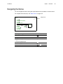
Navigating the Menus
You can navigate the menus using the control buttons on the handset or remote control.
For complete menu structure, see “Menu Trees” on page 135.
Example menu
Live
Image
Menu Directed Inspection
Lamp
Probe Shut Down
Add
Live Annotation
Edit
Video Record
Clear
Desktop
Show
Flashlight
File Manager
Setup Menu
Text
Preset
Arrow
Desired Type of Navigation
Control Button
To open a main menu
To highlight an item
Joystick
To move between a parent menu and submenu
or
To change the highlighted option
Joystick
To select the highlighted item
To exit menus
or
16
Chapter 1 Introduction
GE Inspection Technologies XLG3 VideoProbe System
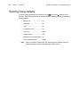
Restoring Factory Defaults
To restore factory defaults press and hold the Save
and Record
Buttons for five
seconds. Then confirm restoration of factory defaults. Performing this action restores the
following options.
•
Battery Icon.
•
Date/Time............................. ..... On
•
Logo..................................... ..... On..
•
Temperature Icon.................. ..... On
•
Text Color.............................. ..... Green
•
Image Format....................... ..... JPG
•
Measurement Accuracy Index ... On
•
Units of Measurement................. Inches
Note
....... ............ ..... On
Upon next restart of VideoProbe, after restoring factory defaults, select the
desired language from the initial language selection screen.
User Manual
Chapter 1 Introduction
17
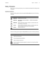
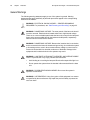
Safety Information
Before using or servicing the system, you must read and understand the following safety
information.
Symbols and Terms
When the following symbols and terms appear in this manual, they have the following
meanings:
Symbol
Term
Meaning
WARNING
DANGEROUS VOLTAGE.
WARNING
ELECTRICAL SHOCK HAZARD — PROPER GROUNDING
REQUIRED.
WARNING
Warning statements indicate conditions or practices that could
result in injury or loss of life.
Caution
Caution statements indicate conditions or practices that could
result in damage to this product or other property.
Caution
Surfaces may be hot.
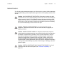
When the following symbols appear on the product, they have the following meanings:
Symbol
Meaning
Chassis grounding point.
See accompanying documentation.
Caution: Surfaces may be hot.
Fuse. For continued protection against fire, replace fuse only with specified
type and rating.
18
Chapter 1 Introduction
GE Inspection Technologies XLG3 VideoProbe System
General Warnings
The following warning statements apply to use of the system in general. Warning
statements that apply specifically to particular procedures appear in the corresponding
sections of the manual.
WARNING ELECTRICAL SHOCK HAZARD — PROPER GROUNDING
REQUIRED. For procedures, see “Safe Powering and Grounding” on page 23.
WARNING DANGEROUS VOLTAGE. The outer panels of the base unit should
never be removed. Electrical shock hazard exists due to high internal voltage.
There are no user serviceable parts inside the base unit, except for the lamp and
fuses, which are accessible through the bottom and side panels, respectively.
Refer all service to listed service centers.
WARNING DANGEROUS VOLTAGE. Because the insertion tube is conductive,
and is connected to the base unit chassis and ground lug, do not allow the system
or its working tools to come in direct contact with any voltage or current source.
Prevent all contact with live electrical conductors or terminals. Damage to the
equipment and/or electrical shock to the operator may result.
WARNING LAMP EMITS ULTRAVIOLET, INFRARED, AND INTENSE VISIBLE
LIGHT. To prevent skin or eye injury, follow these instructions:
•
Avoid looking at or touching the lamp and fiber bundle output while light is on.
•
Do not operate the system when the handset is disconnected from the base
unit.
WARNING POSSIBLE EXPLOSION HAZARD. Do not use this system in
explosive environments.
WARNING USE PROPERLY. Using of any piece of this equipment in a manner
not specified by the manufacturer may impair the product’s ability to protect the
user from harm.
User Manual
Chapter 1 Introduction
19
General Cautions
The following caution statements apply to use of the device in general. Caution statements
that apply specifically to particular procedures appear in the corresponding sections of the
manual.
Caution ALLOW ADEQUATE VENTILATION. Otherwise, the base unit might
overheat. Do not cover or drape anything over the base unit. To ensure adequate
airflow, provide a 3 inch (7.6 cm) distance between the base unit and any solid
objects. When the base unit is installed in the case (the preferred configuration),
the front door of the case must be open during operation to prevent overheating.
It is recommended that you also leave the lids open.
Caution REMOVE POWER PROPERLY. To remove all power from the
equipment, the disconnect device is the AC mains cord and, if equipped, the
battery connector.
Caution HANDLE PROBE CAREFULLY. Keep the insertion tube away from
sharp objects that might penetrate its outer sheath. Keep the whole insertion tube
as straight as possible during operation; loops or bends anywhere in the tube
decrease your ability to steer the probe tip. Avoid bending the insertion tube
sharply; the fragile fibers contained inside may break. Always use the Home
button to straighten the bending neck before withdrawing insertion tube from
inspection area or putting probe away. Never pull, twist, or straighten the bending
neck by hand; internal damage may result. At the first sign of damage, return the
probe for repair.
Caution CERTAIN SUBSTANCES MAY DAMAGE THE PROBE. For a list of
substances that are safe for the probe, see “Chemical Compatibility” on
page 131.
20
Chapter 1 Introduction
GE Inspection Technologies XLG3 VideoProbe System
Informations sur la sécurité
Avant l'utilisation ou l'entretien du système, vous devez lire et comprendre les
informations de sécurité qui suivent.
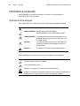
Symboles et termes employés
Voici la signification des symboles et termes suivants employés dans ce manuel :
AVERTISSEMENT TENSION DANGEREUSE.
AVERTISSEMENT RISQUE DE CHOC ELECTRIQUE RACCORDEMENT À LA TERRE OBLIGATOIRE.
AVERTISSEMENT Les avertissements préviennent de situations ou de
pratiques risquant de provoquer des blessures, voire
un danger de mort.
Attention
Les mentions Attention préviennent de situations ou
de pratiques risquant d'endommager le produit ou
d'autres biens.
Attention
Les surfaces concernées peuvent être brûlantes.
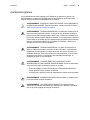
Voici la signification des symboles et termes suivants apposés sur le produit :
Point de retour à la terre sur le châssis.
Voir la documentation jointe.
Attention: Les surfaces concernées peuvent être brûlantes.
Fusible. Pour maintenir la protection contre les risques d'incendie, remplacer le
fusible uniquement par un fusible du type et de l'ampérage spécifié.
User Manual
Chapter 1 Introduction
21
Avertissements généraux
Les avertissements suivants s'appliquent à l'utilisation du système en général. Les
avertissements qui s'appliquent spécifiquement à des procédures particulières sont
indiqués dans les sections correspondantes de ce manuel.
AVERTISSEMENT RISQUE DE CHOC ELECTRIQUE - RACCORDEMENT À
LA TERRE OBLIGATOIRE. Pour les procédures, veuillez consulter la rubrique
“Safe Powering and Grounding” en page 23.
AVERTISSEMENT TENSION DANGEREUSE. Les panneaux extérieurs de la
base ne doivent jamais être enlevés. Le risque de choc électrique est dû à la
présence de tension électrique élevée dans l'unité. La base ne contient aucune
pièce dont l'utilisateur puisse effectuer l'entretien ; les seuls éléments concernés
sont la lampe et les fusibles qui sont respectivement accessibles par le panneau
inférieur et le panneau latéral. Pour les opérations d'entretien, veuillez vous
adresser aux centres de service indiqués.
AVERTISSEMENT TENSION DANGEREUSE. La gaine est conductrice et
reliée au châssis de la base et à la borne de retour à la terre ; ne laissez pas
l'appareil ni ses outils entrer en contact direct avec une source de tension ou
d'intensité électrique. Évitez tout contact avec des conducteurs ou des bornes
électriques sous tension. L'équipement risquerait d'être endommagé, ou
l'opérateur de subir un choc électrique.
AVERTISSEMENT LA LAMPE ÉMET DES ULTRAVIOLETS, DES
INFRAROUGES ET UNE LUMIÈRE VISIBLE INTENSE. Suivez les instructions
ci-dessous pour éviter une blessure cutanée ou oculaire :
•
Évitez de regarder ou de toucher la lampe ou l'extrémité du faisceau de
fibres optiques lorsque la lampe est allumée.
•
N'utilisez pas le système lorsque le manipulateur est déconnecté de la base.
AVERTISSEMENT RISQUE D'EXPLOSION. Ne pas utiliser ce système dans
un environnement à risque d'explosion.
AVERTISSEMENT UTILISER CORRECTEMENT. Si un élément de cet
équipement est utilisé d'une manière non indiquée par le fabricant, l'utilisateur
peut ne plus être protégé des risques de blessure.
22
Chapter 1 Introduction
GE Inspection Technologies XLG3 VideoProbe System
Mentions générales Attention
Les mentions Attention qui suivent s'appliquent à l'utilisation de l'appareil en général. Les
mentions Attention qui s'appliquent spécifiquement à des procédures particulières sont
indiqués dans les sections correspondantes du manuel.
Attention PERMETTRE UNE VENTILATION ADÉQUATE. La base risque de
surchauffer si elle n'est pas bien ventilée. Ne la recouvrez pas avec un tissu ou
quoi que ce soit. Pour assurer un flux d'air adéquat, laissez un écart d'au moins
3 pouces (7,6 cm) entre la base et tout autre objet solide. Lorsque la base est
installée dans son boîtier (configuration recommandée), le panneau avant de
celui-ci doit être ouvert pour éviter la surchauffe de l'appareil pendant son
utilisation. Nous vous recommander de laisser aussi les couvercles ouverts.
Attention METTRE HORS TENSION CORRECTEMENT. Pour mettre
l'appareil totalement hors tension, débranchez le cordon d'alimentation CA et le
connecteur de batterie (le cas échéant).
Attention MANIPULER LA SONDE AVEC PRÉCAUTION. Maintenez la gaine
de la sonde à l'écart d'objets pointus ou tranchants qui risqueraient de traverser
son fourreau. Maintenez toute la gaine aussi droite que possible pendant
l'utilisation : en cas de boucle ou de courbure, il est plus difficile de piloter le bout
de la sonde. Évitez de trop courber la gaine car les fibres optiques qu'elle
contient sont fragiles et risquent de casser. Utilisez toujours le bouton de
rangement pour redresser le collet avant de rétracter la gaine de la zone
d'inspection ou de ranger la sonde. Ne manipulez jamais le collet à la main pour
le tirer, le courber ou le redresser : vous risqueriez de l'endommager à l'intérieur.
Envoyez la sonde en réparation au premier signe d'endommagement.
Attention CERTAINES SUBSTANCES RISQUENT D'ENDOMMAGER LA
SONDE. Pour consulter la liste des substances sans danger pour la sonde, voir
“Chemical Compatibility” en page 131.
23
2
Safe Powering and Grounding
Overview of Safe Powering and Grounding . . . . . . . . . . . . . . . . . . . . . . . . . . . . 23
Verifying AC Earth Ground Path . . . . . . . . . . . . . . . . . . . . . . . . . . . . . . . . . . . . . 24
Grounding With a DC Source (Battery) . . . . . . . . . . . . . . . . . . . . . . . . . . . . . . . . 25
Special Grounding Situations . . . . . . . . . . . . . . . . . . . . . . . . . . . . . . . . . . . . . . . 25
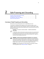
Overview of Safe Powering and Grounding
Safe powering and grounding practices are the responsibility of the user.
In most cases, as described in this chapter, you must connect the system to a lowimpedance earth ground before using it. With that connection, any stray voltage or static
electrical charge on the equipment being inspected will be conducted safely to ground and
will bypass the operator.
WARNING ELECTRICAL SHOCK HAZARD — PROPER GROUNDING
REQUIRED.
In most cases, safe use of this product requires the presence of a protective earth
ground path at the A/C power source. Use of two-conductor extension cords or
any other action that may result in the loss of this ground path are in violation of
the product's safe operating requirements.
WARNING INSPECTION OF ENERGIZED EQUIPMENT. If the equipment
being inspected could be energized relative to earth ground, connect both the
system and the equipment being inspected to earth ground. If that is not possible,
connect the system either to earth ground or to the equipment being inspected,
whichever the user needs to touch. The user should maintain personal electrical
isolation from the other so as to avoid becoming a path to earth ground.
WARNING Before attempting any of the procedures in this chapter, carefully
review all guidelines under “Safety Information” on page 17.
24
Chapter 2 Safe Powering and Grounding
GE Inspection Technologies XLG3 VideoProbe System
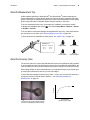
Verifying AC Earth Ground Path
In most cases when using an AC power source, safe use of the XLG3 system requires
verifying a protective earth ground path.
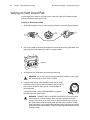
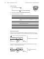
To Verify AC Earth Ground Path
1. Verify that the plugs on the AC cable, and any extension cord, have a ground prong.
Ground prong examples
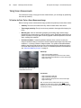
2. Use an ohm meter to measure the resistance from the ground prong to the base unit’s
ground lug to be sure that the AC cable is in good condition.
Ground lug
3. Verify that the AC outlet has a hole for the ground prong.
WARNING Do not use a three-prong grounded plug adapter in a two-prong
wall outlet. Doing so could result in a shock.
4. If a good earth ground is not available through the AC outlet,
connect an external ground wire to the base unit’s ground lug,
then connect the wire to earth ground or to the equipment
being inspected.
Ground
wire
A ground wire (part number XLG3AGROUND) is available
from GE Inspection Technologies.
WARNING CONNECTING TO A VEHICLE INVERTER. If you connect the
XLG3 system to a vehicle inverter, which converts a vehicle's 12-volt DC
power to 110-volt AC, even if the inverter's power outlet has a ground plug,
the XLG3 system is not necessarily earth grounded, since vehicles usually
have rubber tires. You must still connect the base unit’s ground lug to a proper
earth ground and vehicle chassis. Failure to properly ground the base unit can
result in a shock.
User Manual
Chapter 2 Safe Powering and Grounding
25
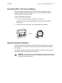
Grounding With a DC Source (Battery)
If you are using an external DC power source, such as the optional battery, while
inspecting potentially energized equipment, safe use of the XLG3 system requires
verifying a protective earth ground path.
To Provide DC Earth Ground Path
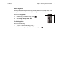
1. Connect an external ground wire to the base unit’s ground lug.
A ground wire (part number XLG3AGROUND) is available from GE Inspection
Technologies.
2. Connect the wire to earth ground or to the equipment being inspected.
Ground lug
Ground
wire
Special Grounding Situations
Contact GE Inspection Technologies Technical Support for guidance prior to using the
XLG3 system in any situation where the probe may come into contact with energized
wires or parts.
For example, inspecting buried pipes that are electrically energized to prevent galvanic
corrosion may require special grounding techniques.
WARNING The XLG3 system and its working tools should never come in direct
contact with any voltage or current source. Damage to the equipment or electrical
shock to the operator may result.
26
Chapter 2 Safe Powering and Grounding
GE Inspection Technologies XLG3 VideoProbe System
27
3
Setting Up and
Putting Away the System
Setting Up the System. . . . . . . . . . . . . . . . . . . . . . . . . . . . . . . . . . . . . . . . . . . . . 27
Changing the Probe. . . . . . . . . . . . . . . . . . . . . . . . . . . . . . . . . . . . . . . . . . . . . . . 30
Changing the Optical Tip . . . . . . . . . . . . . . . . . . . . . . . . . . . . . . . . . . . . . . . . . . . 31
Putting the System Away. . . . . . . . . . . . . . . . . . . . . . . . . . . . . . . . . . . . . . . . . . . 32
Communicating to a PC Through a Router or Network . . . . . . . . . . . . . . . . . . . . 34
Setting Up the System
GE
Inspection Technologies
Everest XLG3
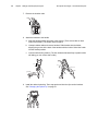
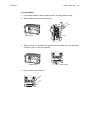
1. Open the case’s lids and front door.
Pull out and turn the front and back latches
counterclockwise. Lift the center handle to open the first
lid. Then open the other lid.
Everest XLG3
2. Determine whether to remove the base unit.
•
If possible, leave the base unit in the case.
•
If necessary for your application, remove the base
unit.
Caution If you leave the base unit in the case, leave the front door open to
prevent overheating. It is recommended that you also leave the lids open.
If you remove the base unit, verify that no accessories or cords are installed
in any of the connectors on the front panel. Otherwise, damage might occur.
3. Verify safe powering and grounding. See “Safe Powering and Grounding” on page 23.
4. Connect to AC power, or attach battery.
•
If using AC power, plug the power cord into a grounded 110 or 220 VAC outlet.
•
If using battery for powering or backup, make sure battery is installed.
5. Turn on the power switch.
6. If this is the first time the system has been powered on, select the desired language.
28
Chapter 3 Setting Up and Putting Away the System
GE Inspection Technologies XLG3 VideoProbe System
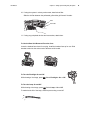
7. Remove the insertion tube.
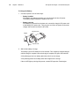
8. Attach the handset to the handle.
a. Slide the handset holder into either of the sockets. (There are sockets on both
sides of the handle.) The holder clicks into place.
b. Unwrap handset cable and remove handset. Slide handset into the holder,
aligning the grooves in the back of the handset with the holder. Swivel the holder
into the desired position.
c.
Lock the swivel ball in position. (The lock holds the handset firmly in position while
still letting you turn it from side to side.)
a
b
c
9. Install the desired optical tip. Then snap probe end into the clip near the handset.
See “Changing the Optical Tip” on page 31.
GE
Inspection Technologies
Everest XLG3
User Manual
Chapter 3 Setting Up and Putting Away the System
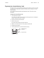
10. If using the system in a dusty environment, install a dust filter.
Slide the air filter between the perforated grill and the grill frame’s five tabs.
Filter
Frame tabs
11. If using any peripheral devices and accessories, attach them.
To Use the Base Unit Removed From the Case
Leave the handset face-down for carrying. Install the handset face-up for use. Slide
handset holder into the socket next to the base unit’s handle.
To Turn the Flashlight On and Off
While viewing a live image, press
. Select Flashlight > On or Off.
To Turn the Lamp On and Off
While viewing a live image, press
. Select Lamp > On or Off.
To maximize the life of the lamp, avoid frequent turning on and off.
29
30
Chapter 3 Setting Up and Putting Away the System
GE Inspection Technologies XLG3 VideoProbe System
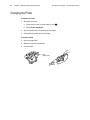
Changing the Probe
To Remove a Probe
1. Shut down the probe.
a. While viewing a live or frozen image, press
b. Select Probe Shut Down.
2. Open the probe latch. The probe pops out slightly.
3. Gently slide the probe out of the handset.
To Install a Probe
1. Open the probe latch.
2. Slide the probe into the handset.
3. Close the latch.
Latch
(partially open)
.
User Manual
Chapter 3 Setting Up and Putting Away the System
31
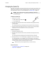
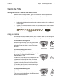
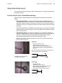
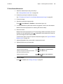
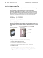
Changing the Optical Tip
Optical tips are threaded onto the probe with a double set of threads to prevent them from
falling into the inspection area. Each optical tip provides a unique depth of field, field of
view, and direction of view. For a list of available tips, see “Optical Tips” on page 141.
Caution Use only finger pressure to remove or attach tips. Using force —
including pliers or other tools — might damage the bending neck. Take care not
to cross the threads.
To Remove an Optical Tip
1. (Optional) Turn off lamp.
a. While viewing a live image, press
.
b. Select Lamp > Off.
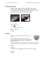
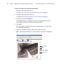
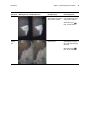
2. Grasp the head of the probe with one hand, and with the other gently turn the tip
counterclockwise.
Turn until the tip spins freely, indicating that it has cleared the first set of threads.
3. Gently pull the tip forward (away from probe). Continue turning counterclockwise,
engaging the second set of threads. Turn until you can remove it.
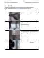
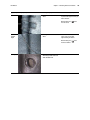
To Attach an Optical Tip
1. Verify that the optical tip is clean.
2. Grasp the head of the probe with one hand, and with the other gently turn the tip
clockwise.
Turn until it spins freely, indicating that it has cleared the first set of threads.
3. Gently push the tip in. Turn clockwise again, engaging the second set of threads.
Turn until finger tight. Do not overtighten. Pull on the tip gently to verify that it is
securely attached. If the second set of threads does not engage, turn the tip slightly in
a counterclockwise direction to allow the threads to connect.
Note
Measurement tips must be tightened firmly to ensure accuracy.
Related Information
•
•
“To Inspect and Clean an Optical Tip” on page 109
“Optical Tips” on page 141
32
Chapter 3 Setting Up and Putting Away the System
GE Inspection Technologies XLG3 VideoProbe System
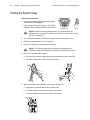
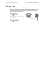
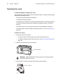
Putting the System Away
To Put the System Away
Everest XLG3
1. Press and hold the button just below the joystick.
The bending neck straightens.
2. If any storage devices are in place, use the Eject
Hardware menu command and then remove them.
Hold this button.
Home
Caution Before removing storage devices, you must use the Eject
Hardware menu command. For details, see “To Eject a Storage Device Other
than DVD” on page 74.
3. Turn off the power switch, and disconnect power cord from the power source.
4. Detach any peripheral devices or accessories.
5. Remove the optical tip, and install the head guard.
Caution The head guard prevents damage to the tip attachment
mechanism. Keep the head guard on whenever no optical tip is in place.
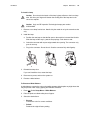
6. Remove the handset and its holder.
a. Pull up on the handset, slightly twisting in either direction until it comes free.
b. Push the release button, and pull up on the holder.
a
b
7. Store the insertion tube in the base unit’s internal storage reel.
a. Straighten any loops or twists in the insertion tube.
b. Feed the insertion tube as far as it goes into the funnel.
c.
Place the handset face-down in the base unit’s handle.
c
b
User Manual
Chapter 3 Setting Up and Putting Away the System
33
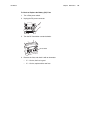
8. Wrap handset cable around the top of the base unit.
Holding the loop in your hand, wrap the cable clockwise under the first lug. Tuck the
cable under the insertion tube. Hook it around the other lug.
Lugs
9. Pack the system into the case.
a. Verify that no accessories or cords are installed in any of the connectors on the
front panel.
b. Pack components securely into case so that no parts will be pinched in the lids.
c.
If you have 6-inch or 12-inch rigidizers, insert them into the holes on the back of
the case. The 6-inch rigidizer rests in the groove. The 12-inch rigidizer sticks out
at the bottom end.
d. Close the lids.
Caution If you do not pack the system carefully, as described here, damage
might occur.
a, b
c
d
34
Chapter 3 Setting Up and Putting Away the System
GE Inspection Technologies XLG3 VideoProbe System
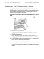
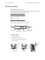
Communicating to a PC Through a Router or Network
PC and network connectivity — wired or wireless — are part of the optional network
package. (See “About the Network Package” on page 5.)
If the XLG3 system is connected to a PC or network, you can send images and videos to
other computers for review, further manipulation, or remeasuring. You can also send
images from other computers to the XLG3 system.
To Connect the XLG3 System to a PC Through a Router or Network Via an Ethernet
Cable
1. At the base unit, plug an Ethernet cable into the Ethernet connector
.
2. Plug Ethernet cable into a network port.
The XLG3 Ethernet connector’s LEDs light up to indicate that the connection is
established.
3. Connecting the XLG3 to a PC:
If a local area network (LAN) port is not available, connect the XLG3 to the PC by
placing an Ethernet router between them. The router will generate an IP address as
described on page 43.
4. No additional software is needed to simply share files with a PC or network via a direct
Ethernet connection, using Microsoft™ Internet Explorer.
5. PC Based Re-Measurement iView - This application lets you manage and measure
images that were captured by the XLG3 system. It also lets you create reports from
those images. To obtain iVIEW PC, contact GE Inspection Technologies.
No software is needed to simply share files with a PC or network via a direct Ethernet
connection.
User Manual
Chapter 3 Setting Up and Putting Away the System
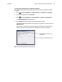
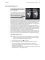
To Connect the XLG3 System to a Wireless Network
The instructions that follow include both “open” (non-encryption) and WEP and WPA
encryption.
1. Press
. Select Setup Menu > Communications > IP Address > Automatic.
2. A checkmark appears next to Automatic.
3. Press
. Select Setup Menu > Communications > Wireless Configuration.
The WiFi Configurations window opens.
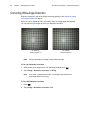
4. Select Detect. Please be patient; this may take several minutes.
If the system detects any network access points, they appear now, listed under the
Auto Detect tab
If the system is connected to a network using both an Ethernet connection and a
wireless connection, the system will use the Ethernet connection by default.
The MAC address is the wireless card’s
unique identifier.
Any detected access points appear here.
Note: The XLG3 supports both wireless B & G.
35
36
Chapter 3 Setting Up and Putting Away the System
GE Inspection Technologies XLG3 VideoProbe System
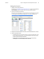
5. Select or enter a network access point.
•
If at least one wireless network name (SSID) - access point is listed under the
Auto Detect tab (shown previously), select the desired access point. Select Save
and Make Default.
•
If no access points are listed, see Manual Entry below.
•
Under SSID, enter the name of the local access point. If a pass key is required for
security, enter the pass key (from your network administrator.) Select Save and
Make Default.
•
If you want to see or manage the access points that have been saved, click the
Saved Settings tab.
You can enter access points manually
under the Manual Entry tab.
Up to five access points may be listed under
the Saved Settings tab. If five access points
are already saved and you want to use a
different one, delete one from this list.
User Manual
Chapter 3 Setting Up and Putting Away the System
37
Manual Entry - Wireless Access Point
The Manual Entry tab is used to enter network information that is either for “hidden “
networks (non-broadcast of wireless name (SSIS)), or to enter networks that are not
presently available.
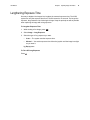
1. To create a manual entry, select the Manual Entry tab, as shown below.
2. Under SSID, enter the name of the local access point (SSID). If a pass key is required
for security, select your appropriate security format (WEP or WPA). Select None when
no security encryption is used.
3. Selecting WPA encryption will require you to define encryption type as AES or TKIP.
Contact your local network administrator to define this information.
4. When WEP or WPA are selected, the appropriate entry field will be enabled. Next,
select Save or Save and Make Default.
5. Return to the Setup Menu > Communications, select Automatic. A check mark will
appear next to Automatic.
6. Exit out of the Communications Menu by selecting the Back button. Wait
approximately 20 seconds and then return to the Setup Menu > Communications
and an IP address should now be present.
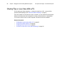
For FireFox browser access, see Using the Desktop (page 90).
38
Chapter 3 Setting Up and Putting Away the System
GE Inspection Technologies XLG3 VideoProbe System
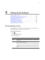
39
4
Setting Up the Software
Reviewing Settings for Audio. . . . . . . . . . . . . . . . . . . . . . . . . . . . . . . . . . . . . . . . 39
Reviewing Settings for Image Format and Quality . . . . . . . . . . . . . . . . . . . . . . . 40
Reviewing the Setting for Video Quality . . . . . . . . . . . . . . . . . . . . . . . . . . . . . . . 41
Reviewing Settings for Text Color . . . . . . . . . . . . . . . . . . . . . . . . . . . . . . . . . . . . 42
Reviewing Settings for a Logo . . . . . . . . . . . . . . . . . . . . . . . . . . . . . . . . . . . . . . . 42
Reviewing Settings for Measurement . . . . . . . . . . . . . . . . . . . . . . . . . . . . . . . . . 43
Reviewing Settings for the System . . . . . . . . . . . . . . . . . . . . . . . . . . . . . . . . . . . 44
Reviewing Settings for Communications . . . . . . . . . . . . . . . . . . . . . . . . . . . . . . . 45
Reviewing Settings for Audio
Audio settings affect only audio output, not input. If you want to turn off audio input for
video recording, you can do so before you start recording.
To Review Settings for Audio
1. Press
.
2. Select Setup Menu > Audio.
3. Select the desired item:
Item
Description
Volume
Adjust the volume to the internal speaker and headphone output. This control does not affect
line-level output.
Mic
On, muted or disabled. When on, live audio is sent from the microphone to the line-level output,
and audio is saved during video recording.
When muted, live audio is not recorded, but an audio track is created on MPEG2 recordings.
When disabled, live audio is not sent to any outputs, and no audio track is created on MPEG2
recordings. The system still does save audio comments that you choose to record for still
images.
40
Chapter 4 Setting Up the Software
GE Inspection Technologies XLG3 VideoProbe System
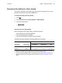
Reviewing Settings for Image Format and Quality
If you want to choose the format or quality for a particular image you want to capture, you
must change the setting before capturing that image.
To Change Settings for Image Format and Quality
1. Press
.
2. Select Setup Menu > Still Save.
3. Select the desired settings:
•
Save Format — JPEG or Bitmap
•
JPEG Quality — High or Low
Stereo measurement JPEGs are always saved at high quality, even if this setting
is Low.
Decision Factors for Image Format and Quality
When changing format and quality settings, consider these factors:
•
•
•
•
which format is required or preferred
(for JPEGs only) whether high or low quality is more appropriate
how much storage space is available
how many files (images and videos) need to be stored
This table may help you determine the best settings for your situation.
Storage Capacities (Approx. Number of Images)b
File Format and
Quality
Typical File Sizea
2.7 GB
Internal Drivec
512 MB
Removable Storage Device
BMP
900 KB
~3000
568
JPEG High
200 KB
~13,500
2560
JPEG Low
60 KB
~50,000
8533
a. File size varies by image content. These sizes are based on typical NTSC images; PAL images are 10% larger.
b. Audio (WAV) files consume about 120 KB for every 15 seconds of audio. Image storage capacity must be reduced by
the amount of audio recorded.
c. To learn how to check the available memory on your internal drive, see “Reviewing Settings for the System” on page 44.
User Manual
Chapter 4 Setting Up the Software
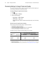
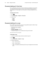
Reviewing the Setting for Video Quality
If you want to choose the video quality, you must change the setting before you record.
All videos are FMV (full-motion video) MPEG2 files.
To Change the Setting for Video Quality
1. Press
.
2. Select Video Record > Recording Options > MPEG Quality.
3. Select the desired setting:
•
•
MPEG2 High
MPEG2 Low
Decision Factors for Video Quality
When changing the video quality setting, consider these factors:
•
•
•
which quality level is required or preferred
how much storage space is available
how many files (images and videos) need to be stored
This table may help you determine the best settings for your situation.
Storage Capacities (Approx. Number of Seconds)b
Typical File Sizea
2.7 GB
Internal Drivec
512 MB Removable
Storage Device
4.3 GB
DVD
MPEG2 High
1 MB/s
~42 min
~8 min
~1 hr, 10 min
MPEG2 Low
0.5 MB/s
~1 hr, 24 min
~17 min
~2 hr, 20 min
MPEG Quality
a. File size varies by image content. These sizes are based on typical NTSC images; PAL images are 10% larger.
b. Audio files, which consume approx. 300 KB per second of video, are saved with video files.
c. To learn how to check the available memory on your internal drive, see “Reviewing Settings for the System” on
page 44. The available memory also appears on the Recording Options screen; see “Recording Live Video” on
page 69.
41
42
Chapter 4 Setting Up the Software
GE Inspection Technologies XLG3 VideoProbe System
Reviewing Settings for Text Color
You can change the color of text and other elements that are displayed over the images
(for example, the dashed line that you center over the shadow when taking shadow
measurements). The most legible color will vary with the coloring and brightness of the
image.
To Change the Text Color
1. Press
.
2. Select Setup Menu > Graphics > Text Color.
3. Select a color:
•
•
•
White
Black
Green
Reviewing Settings for a Logo
You can add a logo to the screen. You can use any graphics program to create the logo,
as long as you save it with these attributes:
•
•
•
•
•
Microsoft Windows-compatible
24-bit color
200 pixels x 200 pixels maximum
file name LOGO.BMP
transparent background color (if desired): red 128, green 128, blue 0
The system can store only one logo file.
To Work With a Logo
1. Insert the removable storage device that contains the logo file.
2. Press
.
3. Select Setup Menu > Graphics > Logo.
4. Select the desired item:
•
On — Turns the logo on.
•
Off — Turns the logo off.
•
Load — Automatically installs the logo file from your storage device to the internal
drive.
User Manual
Chapter 4 Setting Up the Software
43
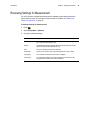
Reviewing Settings for Measurement
For XLG3 systems equipped with measurement capability, these settings determine
system behavior when you are taking measurements. For details, see “Measuring
Features and Defects” on page 87.
To Review Settings for Measurement
1. Press
.
2. Select Setup Menu > Measure.
3. Change any desired settings.
Item
Description
Stereo
The Cal Info option displays calibration data for the selected stereo tip. All other options
are for factory-authorized personnel only.
Shadow
The Cal Info option displays calibration data for the selected shadow tip. All other
options are for factory-authorized personnel only.
Units
Inches, mm. Determines which units are displayed.
Set Min Index
Accuracy index’s minimum value. If the index drops below this value, it flashes.
Index Display
On, off. Determines whether the accuracy index is displayed.
User Prompts
On, off. Determines whether user prompts are displayed in measurement mode.
Only trained professionals should turn these prompts off.
44
Chapter 4 Setting Up the Software
GE Inspection Technologies XLG3 VideoProbe System
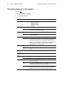
Reviewing Settings for the System
1. Press
.
2. Select Setup Menu > System.
3. Select the desired item:
Item
Choices
System Info
Language
Time/Date
Steering
Description
System information appears:
• Total memory capacity
• Remaining memory
• Software revision levels
• Language
Select
Choose from a list of languages.
Load
System automatically installs a language file from an external storage device,
if any. You must then select the language.
Show
On, off.
Set
Change the time or date. Time is always in 24-hour format. Date is always in
day/month/year format.
Tip Map
On, off. The tip map is a grid that indicates probe-tip position.
Zoom Mode
Steer Only — In this mode, when you move the joystick in a zoomed live
view, the probe tip articulates. The image changes as the camera moves.
Pan Only — In this mode, when you move the joystick in a zoomed live view,
the probe tip does not articulate. The image changes as the system
electronically pans the camera’s full view.
MDI
Load, Unload
Load or unload an existing inspection on the XLG3.
Annotate -- On,
Off
If off, the menu-directed inspection on-screen prompts are not saved in the
image.
Update
Software
For use with the XLG3 Update Software CD-ROM or thumbdrive.
Feature
Update
For use with the XLG3 Feature Installation CD-ROM or thumbdrive.
Video Output
Format
NTSC
Standard in US and elsewhere.
PAL
Standard in Europe and elsewhere.
LCD Display
Full
The image fills the screen. The top and bottom are cropped. There are no
black bands at the sides.
4x3
The complete image that the camera “sees” is displayed. The top and bottom
are not cropped. There are bands of black at the sides.
Unscaled
The image nearly fills the screen. The top and bottom are slightly cropped;
there are narrow bands of black at the sides. Unscaled is automatically
selected when measuring for most accurate placement of cursors.
User Manual
Chapter 4 Setting Up the Software
45
Reviewing Settings for Communications
Communications settings are part of the optional network package. (See “About the
Network Package” on page 5.)
The communications settings apply to XLG3 systems connected to a PC or network.
Note
The XLG3 system is designed to operate in a protected computing environment
behind a firewall.
To Review Settings for Communications
1. Press
.
2. Select Setup Menu > Communications.
3. Change any desired settings.
Item
Choices
Unit Name
Description
Displays the system’s serial number.
IP Address
None, Automatic, Displays the system’s IP address and lets you select a setting. Select the
or Advanced
setting recommended by your network administrator. Note: When
establishing communications with a PC, the setting must be Automatic.
Remote File
Access
Disallow
Prevents remote users from accessing files stored on the XLG3 system.
Allow Read
Lets remote users read and copy files stored on the XLG3 system.
Allow Read/
Write
Lets remote users read and copy files stored on the XLG3 system and
transfer files to the system.
Relink Now
Establishes communications between the network and a newly connected
XLG3 system that was already turned on when you connected it.
Wireless
Configuration
Displays wireless settings. Lets you select a wireless access point.
Video
streaming
On/off
Lets remote users view live video. When video streaming is on, video cannot
be recorded to the DVD drive.
46
Chapter 4 Setting Up the Software
GE Inspection Technologies XLG3 VideoProbe System
47
5
Capturing Images and Videos
Process Overview . . . . . . . . . . . . . . . . . . . . . . . . . . . . . . . . . . . . . . . . . . . . . . . . 47
Steering the Probe. . . . . . . . . . . . . . . . . . . . . . . . . . . . . . . . . . . . . . . . . . . . . . . . 49
Freezing an Image. . . . . . . . . . . . . . . . . . . . . . . . . . . . . . . . . . . . . . . . . . . . . . . . 50
Working With a Recalled Image . . . . . . . . . . . . . . . . . . . . . . . . . . . . . . . . . . . . . 51
Working With a Split Screen . . . . . . . . . . . . . . . . . . . . . . . . . . . . . . . . . . . . . . . . 52
Adjusting the Brightness . . . . . . . . . . . . . . . . . . . . . . . . . . . . . . . . . . . . . . . . . . . 53
Reducing “Noise” in Dark Images . . . . . . . . . . . . . . . . . . . . . . . . . . . . . . . . . . . . 54
Correcting Wide-Angle Distortion . . . . . . . . . . . . . . . . . . . . . . . . . . . . . . . . . . . . 56
Lengthening Exposure Time . . . . . . . . . . . . . . . . . . . . . . . . . . . . . . . . . . . . . . . . 57
Enhancing Contrast . . . . . . . . . . . . . . . . . . . . . . . . . . . . . . . . . . . . . . . . . . . . . . . 58
Zooming. . . . . . . . . . . . . . . . . . . . . . . . . . . . . . . . . . . . . . . . . . . . . . . . . . . . . . . . 58
Inverting an Image. . . . . . . . . . . . . . . . . . . . . . . . . . . . . . . . . . . . . . . . . . . . . . . . 59
Annotating With Text or Arrows . . . . . . . . . . . . . . . . . . . . . . . . . . . . . . . . . . . . . . 60
Saving an Image . . . . . . . . . . . . . . . . . . . . . . . . . . . . . . . . . . . . . . . . . . . . . . . . . 65
Working With Videos . . . . . . . . . . . . . . . . . . . . . . . . . . . . . . . . . . . . . . . . . . . . . . 67
Process Overview
The process of capturing images and recording videos may be simple or complex,
depending on what you want to accomplish.
You can record audio comments for still images or videos using the built-in microphone in
the handset, an external microphone, or a headset microphone.
For an illustration, see “Process Diagram: Capturing Images and Videos” on page 48.
48
Chapter 5 Capturing Images and Videos
GE Inspection Technologies XLG3 VideoProbe System
Process Diagram: Capturing Images and Videos
Steer probe.
(Optional)
Start recording video.
Make audio comments if desired.
(Optional)
Work with the displayed image.
“Steering the Probe” on page 49
“Working With Videos” on page 67
“Freezing an Image” on page 50
“Working With a Recalled Image” on page 51
“Working With a Split Screen” on page 52
“Adjusting the Brightness” on page 53
“Reducing “Noise” in Dark Images” on page 54
“Correcting Wide-Angle Distortion” on page 56
“Lengthening Exposure Time” on page 57
“Enhancing Contrast” on page 58
“Zooming” on page 58
“Inverting an Image” on page 59
“Annotating With Text or Arrows” on page 60
“Measuring Features and Defects” on page 87
(Optional)
Save still images.
Make audio comments if desired.
“Saving an Image” on page 65
If recording video, stop.
“To Stop Recording” on page 70
Done
User Manual
Chapter 5 Capturing Images and Videos
49
Steering the Probe
Guiding the Insertion Tube Into the Inspection Area
With the desired optical tip installed, guide the insertion tube into the inspection area.
Use your hands to push the tube until it reaches an area you want to inspect.
Twist the insertion tube gently to bring the desired scene into view.
Accessories are available to make it easier to maneuver the tube:
•
Rigidizers, long thin pipes that keep the tube straight as you insert it, are available in
different lengths.
•
A gripper is a cylindrical handle that slides over the insertion tube to make it easier to
control. Grippers are threaded to connect to rigidizers and to access port couplers.
Rigidizer
Gripper
Aiming the Camera
A live image is the image that the camera “sees” in real time. When you are viewing a live
image, you can aim the camera by controlling the bending neck in various ways.
To Articulate the Bending Neck
Everest XLG3
While viewing a live image, move the joystick toward
the feature you want to see. The bending neck
articulates so that the probe tip moves in that same
direction.
Move the joystick.
360q All-Way®
articulation
To Hold the Bending Neck in Place
(Steer-and-Stay Mode)
Press the button just below the joystick. Press quickly;
do not hold. The letters SS appear, indicating
Steer-and-Stay™ mode.
In this mode, the bending neck holds its position even
when you let go of the joystick. If you move the
joystick while in Steer-and-Stay mode, the bending
neck articulates slowly. When you stop moving the
joystick, the bending neck stays in the new position.
Everest XLG3
Press this button.
Steer-and-Stay
To exit Steer-and-Stay mode, press the button again.
The letters SS disappear.
To Straighten the Bending Neck
(HOME)
Everest XLG3
Press and hold the button just below the joystick.
The bending neck straightens for safe withdrawal and
storage of the insertion tube.
Hold this button.
Home
50
Chapter 5 Capturing Images and Videos
GE Inspection Technologies XLG3 VideoProbe System
Freezing an Image
Freezing an image captures it temporarily for review or adjustment.
When you move the joystick in a frozen view, the probe tip does not articulate. If you zoom
in on a frozen image and then move the joystick, the image changes as the system
electronically pans the camera’s full view.
To Freeze an Image
Everest XLG3
Press
or the trigger.
The image freezes. The letters FF (for freeze
frame) appear.
Freeze
To Unfreeze an Image
Press
, or the trigger, or
.
User Manual
Chapter 5 Capturing Images and Videos
51
Working With a Recalled Image
To Work With a Recalled Image
1. Recall the desired image.
a. Press
.
b. Select File Manager > Recall > drive or device.
c.
Select a file. It opens.
Note
When viewing a recalled image, you can cycle through the other images
stored in the same folder by moving the joystick.
2. Determine your next action.
•
To rename the image, press
. Select Rename Image. Enter a new file name.
The new name overwrites the old.
•
To play recorded audio comments, if any, press
•
To record comments, press
the microphone.
. Select Play Audio.
. Select Record (or Re-record) Audio. Speak into
For information on general tasks — adjusting brightness, zooming, annotating, saving,
etc. — see “Process Diagram: Capturing Images and Videos” on page 48.
52
Chapter 5 Capturing Images and Videos
GE Inspection Technologies XLG3 VideoProbe System
Working With a Split Screen
A split screen displays two images side-by-side in
any combination of live, frozen, or recalled. Only one
side is active at a time, as indicated by an arrow.
Live
FF
Still images in half-screen view are cropped
horizontally. You can use the joystick to pan side-toside within these images.
Active
To Work With a Split Screen
1. Split the screen.
Press
. Select Image > Split Screen.
On the left, a live image appears. On the right, the previous full-screen image appears
at half-screen size. If it was previously live, it is now frozen.
2. (Optional) Change active sides, or temporarily view one image at full size.
a. Press
.
b. Select Split Options.
c.
Select any items:
Item
Description
Left/Right > Active
The selected side becomes active.
Left/Right > Full Screen
The selected side’s image fills the screen.
When finished viewing, press
Back to split screen
. Select View other image or
For information on general tasks — adjusting brightness, zooming, annotating, saving,
etc. — see “Process Diagram: Capturing Images and Videos” on page 48.
3. When ready, exit the split screen.
•
To return immediately to a live image, press
.
•
To select one of the displayed images to view upon exiting, press
Select Split Options > Left/Right > Close.
.
User Manual
Chapter 5 Capturing Images and Videos
53
Adjusting the Brightness
You can adjust the brightness of live, frozen, and recalled images as well as recorded
video.
When viewing live images, adjusting the brightness means controlling exposure time and
camera gain. When viewing still images or recorded video, adjusting the brightness
means controlling digital gain.
The brightness saved will be the brightness recalled.
To Adjust the Brightness
1. Press
.
2. Select Image > Brightness.
3. Adjust.
54
Chapter 5 Capturing Images and Videos
GE Inspection Technologies XLG3 VideoProbe System
Reducing “Noise” in Dark Images
Adaptive Noise Reduction (ANR) is part of the image processing package. (See “About
the Image Processing Package” on page 4.)
When the probe is in a dark area, the live image is often noisy, or grainy (“crawling pixels”).
You can improve such images by turning on ANR in either of two modes:
•
ANR normal — Reduces noise without any brightening.
•
ANR enhanced — Reduces noise and brightens dark areas. (Does not brighten areas
that are already bright.)
Note
ANR annotation is saved with image.
ANR off
ANR off
ANR normal
(Noise is reduced without brightening.)
ANR enhanced
(Noise is reduced and dark areas are brightened.)
User Manual
Chapter 5 Capturing Images and Videos
To Turn On ANR
1. While viewing a live image, press
.
2. Select Image > Adaptive Noise Reduction > Normal or Enhanced.
Note
When ready to capture an image, keep the probe head as still as possible.
When the probe head is moving, noise increases.
To Turn Off ANR
1. Press
.
2. Select Image > Adaptive Noise Reduction > Off.
55
56
Chapter 5 Capturing Images and Videos
GE Inspection Technologies XLG3 VideoProbe System
Correcting Wide-Angle Distortion
Distortion correction is part of the image processing package. (See “About the Image
Processing Package” on page 4.)
When you use an optical tip with a 120° field of view, the image edges are distorted.
You can improve such images by turning on distortion correction.
120° optical tip,
distortion correction off
Note
120° optical tip,
distortion correction on
120 Deg annotation on image is saved with the image.
To Turn On Distortion Correction
1. While viewing a live image with a 120° optical tip installed, press
.
2. Select Image > Distortion Correction > 120 Deg.
Note
If you enter a measurement mode, a corrected image reverts to its
uncorrected state for accuracy.
To Turn Off Distortion Correction
1. Press
.
2. Select Image > Distortion Correction > Off.
User Manual
Chapter 5 Capturing Images and Videos
57
Lengthening Exposure Time
One way to brighten live images is to lengthen the camera’s exposure time. The XLG3
system can vary the exposure time from 1/10,000 second to 12 seconds. The longer the
exposure, the greater the risk of blurring the image. Keep the probe tip as still as possible
when capturing an image with a long exposure.
To Lengthen Exposure Time
1. While viewing a live image, press
.
2. Select Image > Long Exposure.
3. Select the type of long exposure you want.
•
Auto — The system sets the exposure time.
•
Manual — You set the exposure time. Move the joystick until the image is as light
as you want it.
Lg Exp appears.
To Turn Off Long Exposure
Press
.
58
Chapter 5 Capturing Images and Videos
GE Inspection Technologies XLG3 VideoProbe System
Enhancing Contrast
When there is not enough light or contrast to see important features or defects —
for example, when you need to position cursors accurately for measurements —
“Inverse +” may help. This feature reverses the brightness like a photographic negative.
It enhances the image contrast, making subtle details more visible.
You can enable “Inverse +” for any live, frozen, or recalled image.
“Inverse +” off
“Inverse +” on
To Turn “Inverse +” On
1. Press
.
2. Select Image > Inverse + > On.
To Turn “Inverse +” Off
Press
.
Zooming
You can zoom in and out for all types of images: live, frozen, and
recalled.
Everest XLG3
Zooming is digital, so pixelation increases as you zoom in.
The system cycles through the zoom levels in increments up to 3.0x.
When an image is zoomed, its zoom level (for example ZM 2.6)
appears on the screen.
Zoom
To learn about the two zoom modes, which determine what happens when you move the
joystick in a zoomed live view, see “Reviewing Settings for the System” on page 44.
To Zoom
Press
.
For larger increments, press
To Unzoom
Press
.
repeatedly. For smaller increments, hold
.
User Manual
Chapter 5 Capturing Images and Videos
59
Inverting an Image
The Invert function flips an image horizontally. You can invert a live, frozen, or recalled
image.
You may want to invert images when using a side-view optical tip, since these tips contain
a prism that inverts images, causing text to appear backwards.
Invert
Invert off
To Invert an Image
1. Press
.
2. Select Image > Invert > On.
To Uninvert an Image
Press
.
Invert on
60
Chapter 5 Capturing Images and Videos
GE Inspection Technologies XLG3 VideoProbe System
Annotating With Text or Arrows
Annotating an XLG3 image means adding text or arrows to point out areas of interest:
cracks, defects, etc. You can annotate live, frozen, and recalled images.
You can create two types of annotation:
•
Live annotation is general information — relevant to the entire inspection or a
significant portion of it — to be displayed constantly except when hidden. You can
show or hide live annotation any time. You would use live annotation, for example,
while recording video. To add or clear live annotation, you must be viewing a live
image. When you’re viewing a still image, you can choose whether to show or hide the
live annotation.
•
Still annotation is information that is specific to a particular image. To display or add
still annotation, you must be viewing a still image (frozen or recalled). When you return
to a live image, still annotation is cleared.
If you anticipate using certain text over and over, you may want to create one or more
presets — ready-to-use annotations. You can create multiple presets for use in either live
or still annotations. Maximum = 100 presets, 5 lines per preset, 28 characters per line.
To Annotate a Live Image
1. Press
.
2. Select Live Annotation.
3. Select the desired item:
Item
Choices
Description
Text
Add
Create text for use in a live annotation.
Edit
Edit existing live text annotations.
Delete
Deletes all live annotation text from the screen and from memory.
Add
Create an arrow for use in a live annotation.
Edit
Edit existing live arrow annotations.
Delete
Deletes all live annotation arrows from the screen and from memory.
Create
Add a new text annotation to the preset manager.
Recall
Select an existing text annotation from the preset manager to place.
Edit
Edit an existing text annotation from the preset manager.
Delete
Delete an existing text annotation from the preset manager.
Import
Load a .txt file containing presets (see page 61 for details).
Export
Export a .txt file containing presets.
On, Off
Turns live annotation (text and arrows) on or off.
Arrow
Preset
Show
User Manual
Chapter 5 Capturing Images and Videos
61
To Annotate a Still Image
1. Press
.
2. Determine whether to display or hide live annotation, if any.
Select Live Annotation > Show > On or Off.
3. Select Still Annotation.
4. Select the desired item.
Item
Choices
Description
Text
Add
Create text for use in a still annotation.
Edit
Edit existing still text annotations.
Delete
Deletes all still annotation text from the screen and from memory.
Add
Create an arrow for use in a still annotation.
Edit
Edit existing still arrow annotations.
Delete
Deletes all still annotation arrows from the screen and from memory.
Create
Add a new text annotation to the preset manager.
Recall
Select an existing text annotation from the preset manager to place.
Edit
Edit an existing text annotation from the preset manager.
Delete
Delete an existing text annotation from the preset manager.
Import
Load a .txt file containing presets (see page 61 for details).
Export
Export a .txt file containing presets.
On, Off
Turns still annotation (text and arrows) on or off.
Arrow
Preset
Show
Note
In addition to annotating with text and arrows, you can also add audio comments
to a still image in either of two ways:
•
Immediately after saving an image, you can select Record Audio.
•
If viewing a recalled image, you can press
Record Audio.
, and then select Audio >
Note
Changing the display size will change annotations location and may cause
annotation to be cut off.
Note
•
Preset .txt files may contain presets less than 28 characters each.
•
Up to 100 presets may be loaded.
62
Chapter 5 Capturing Images and Videos
GE Inspection Technologies XLG3 VideoProbe System
To Use the Text-Entry Screen
You use the text-entry screen when creating an annotation or preset.
Note
For faster text entry, you can use a USB keyboard.
Use Joystick/
to place characters
when done
YOUR TEXT HERE.
Your text cursor
Character window
!@#$%^&*()_+~|
ÀÁÂÄACR
1234567890-= \
ÈÉÊËÇDS
ABCDEFGHIJ[]{}
Ì Í Î Ï ÑNT
KLMNOPQRS;:
ÒÓÔÖŸÝ
TUVWXYZ,./?<>
ÙÚÛÜUZ
Add to Presets
Preset
Enter
Backspace
Highlighted character
Delete
1. If necessary, position your text cursor.
a. Move the joystick to highlight an arrow key
b. Press
c.
in the character window.
on the handset. Your text cursor moves in the selected direction.
Repeat until your text cursor is in the desired position
2. Move the joystick to highlight the desired item in the character window.
•
If you want to add a character, highlight that character.
For a space, highlight any blank.
•
If you want to start a new line, highlight .
•
If you want to delete a character, highlight
3. Press
or
.
on the handset to activate the highlighted item.
4. Repeat from Step 1 until you are finished creating your annotation.
5. Press
. The text-entry screen disappears. Your text is displayed.
6. Determine what to do next.
•
If you have just created an annotation, move it to the desired location.
•
If you have just created a preset, follow the on-screen instructions.
User Manual
Chapter 5 Capturing Images and Videos
63
To Load a Preset File
To load a file containing multiple presets onto the XLG3 VideoProbe, a file may be created
on a PC. This file must conform to the following:
•
Line-delimited (each preset must be on a separate line)
•
File Type - .txt
•
Encoding - UTF-8
•
Recommended Program - Microsoft Notepad
At the time of saving the document, select .txt as the File Type and UTF-8 as the Encoding
(as shown below).
Loading the File
1. Save the Preset.txt file onto external media (CF Card, USB ThumbDrive, etc.).
2. Insert the external media in your XLG3 VideoProbe.
3. Press
.
4. Select Live Annotation.
5. Select Preset > Load.
6. Locate the file that you have created.
64
Chapter 5 Capturing Images and Videos
GE Inspection Technologies XLG3 VideoProbe System
Annotating with Alternate Input Methods
The XLG3 VideoProbe supports text entry with advanced input methods for Simplified
Chinese (Pinyin) and Japanese (Hiragana to Katakana/Kanji). To utilize these input
methods the user must have an external keyboard connected to their VideoProbe. These
input methods default as active when either Chinese or Japanese are selected as the
system language. To return to an on-screen keyboard that doesn’t utilize an input method,
toggle the button that reads “Input Method -/O“.
Chinese
The XLG3 VideoProbe supports the Pinyin text entry method. For each word or phrase
that you wish to enter, follow the steps below:
1. Using the external keyboard, type the Pinyin representation of the character to be
entered.
2. Use the numbers on the external keyboard to select the desired character from the
candidate list.
3. Press the enter key on the external keyboard to confirm the selection.
Japanese
The XLG3 VideoProbe supports a text entry method that converts Hiragana to Katakana
and Kanji characters. For each word or phrase that you wish to enter, follow the steps
below:
1. Using the external keyboard, type the Hiragana that make up the word being entered.
2. When all of the Hiragana that make up the word are entered, press the space bar on
the external keyboard to get a candidate list of Katakana and Kanji characters.
3. Use the numbers on the external keyboard to select the desired word or phrase from
the candidate list.
4. Press the enter key on the external keyboard to confirm the selection.
Note
•
If the desired word or phrase is not shown in the candidate list, press Page
Up/Page Down on the external keyboard to cycle through more candidates.
•
A maximum of 6 Hiragana may be entered for each word or phrase for
Japanese text entry
User Manual
Chapter 5 Capturing Images and Videos
65
Saving an Image
Saving an image is like taking a snapshot. Most screen elements — date, time, zoom
level, annotations, measurements, etc. — become part of the saved image. What you see
is what you save.
You can save live, frozen, split-screen, or recalled images.
There are two save modes:
•
Normal
Saves the image without calibration data. When you recall a normal image, you
cannot take measurements.
•
Measurement
Saves the image with calibration data for the selected measurement tip. When you
recall a measurement image, you can take measurements.
Related Information
•
•
•
“To Save an Image” on page 66
“Reviewing Settings for Image Format and Quality” on page 40
“Managing Files & Communicating With Other Computers” on page 73
66
Chapter 5 Capturing Images and Videos
GE Inspection Technologies XLG3 VideoProbe System
To Save an Image
Everest XLG3
1. (Live or still images) Press
.
-or(Still images only) Press
. Select Save or Save Image.
Save
2. If the choice is available, select Normal or Measurement.
3. Select the desired option or options.
Option
Description
Save
Saves the image file.
Select Save Folder
Lets you select a save folder before you save the file. If you insert a storage
device after selecting this menu item, select Refresh Drive List to update the list
of choices.
Eject Hardware
(Applicable only for removable storage devices.) Ejects the storage device.
Rename Image
Lets you name the file before you save it. If you do not name the file before
saving it, the system assigns a name.
Record Audio
Lets you speak into the microphone to record comments.
Play Audio
Plays recorded comments, if any.
Delete Audio
Deletes recorded comments, if any.
About Image File Names
Unless you run a menu directed inspection, images have a generic format. You can
rename them after recalling them, or you can rename them any time from the desktop.
M = shadow or stereo image saved with measurement data
YYMMDDXXXX.FFF
Date
(year, month, day)
Unique identifier
(from 0001
to 9999)
Default naming scheme for image files
Format
(BMP or JPG)
During a menu directed inspection, the file names are determined by the on-screen
selections — files are automatically named.
XYZ . . . . XXXX.FFF
Determined by menu
directed inspection
Unique identifier
(from 0001
to 9999)
Format
(BMP or JPG)
Menu directed inspection naming
scheme
User Manual
Chapter 5 Capturing Images and Videos
67
Working With Videos
Any time during your inspection you can record video “in the background” while doing
other tasks, such as adjusting brightness, comparing images on a split screen, capturing
still images, taking measurements, managing files and folders, etc.
When you record video, the XLG3 system saves everything that appears on the display,
including menus that you open, as well as background sounds and comments made near
the microphone (unless you turn off the audio).
You can record video onto the internal drive, a DVD, or any other removable storage
device.
Related Information
•
•
•
“About DVDs” on page 68
“Recording Live Video” on page 69
“Working With a Recalled Video” on page 72
68
Chapter 5 Capturing Images and Videos
GE Inspection Technologies XLG3 VideoProbe System
About DVDs
The optional DVD drive can be used for two purposes:
•
•
to record live MPEG2 video files
to archive saved files (images or videos)
Do not turn off the system while recording or archiving to a DVD, or you will lose data.
When video streaming is on, video cannot be recorded to the DVD drive. To learn how to
turn video streaming on and off, see “Reviewing Settings for Communications” on
page 45.
Caution DVD recording and archiving are sensitive to extremes of temperature,
dust, vibration, and shock. For best results, minimize these factors.
DVD Types Accepted
The XLG3 system accepts both DVD+Rs and DVD-Rs.
You can record and/or archive to the same DVD multiple times until it is full.
SCB Version
DVD-R
DVD+R
Maximum umber of allowed
starts, stops, and archived
commands
Maximum umber of allowed
starts, stops, and archived
commands
02.00.06
35
14
02.00.09
35
14
02.01.XX
33
10
Recommended Brands
Verbatim or Sony
Verbatim or Maxell
Initializing DVDs
If you start recording or archiving to a new DVD that has not been initialized manually, the
system automatically initializes it before recording or archiving.
To Initialize a DVD Manually
1. Press
.
2. Select Video Record > DVD Initialize.
The system initializes the DVD for about 2 minutes. After the DVD is initialized, you
can start recording or archiving whenever you are ready.
Related Tasks
•
•
•
“Recording Live Video” on page 69
“Archiving (Copying) Files to a DVD” on page 77
“To Eject a DVD” on page 74
User Manual
Chapter 5 Capturing Images and Videos
69
Recording Live Video
Before recording video to a DVD, read “About DVDs” on page 68.
To Start Recording, Using Menus
1. Press
quickly.
- or Press
. Select Video Record > Recording Options.
The Video Recording Options menu appears.
2. Select the desired option or options.
Option
Description
Start Recording
A flashing red dot appears. As long as this dot is flashing, the system is recording.
If using a DVD, recording starts only after the DVD drive light stops flashing. If you start
recording to a new DVD that has not been initialized manually, the system
automatically initializes it before recording. See “Initializing DVDs” on page 68.
Cancel
Exits the menu without recording.
MPEG Quality
MPEG2 High or MPEG2 Low.
For decision factors, see “Reviewing the Setting for Video Quality” on page 41.
Mic
On, muted or disabled.
Select Drives
Lets you select the drive or drives to record to. When you record to a DVD, it is
recommended that you select a backup drive for simultaneous recording. When you
record to a compact flash card, special considerations apply:
• If you use a compact flash card, it must be an industrial card.
• Videos are always saved to the compact flash slot at MPEG2 low quality, even if you
select MPEG2 high.
• If you record simultaneously to the compact flash slot and a DVD, videos are always
saved at MPEG2 low quality to both media.
Select Save Folder
(For any drive other than DVD) Lets you select a save folder on the selected drive.
Name Video
Lets you name the file before recording. If you do not name the file before recording,
the system assigns a name.
70
Chapter 5 Capturing Images and Videos
GE Inspection Technologies XLG3 VideoProbe System
To Quick-Record, Bypassing Menus
Press and hold
.
A flashing red dot appears. As long as this dot is flashing, the system is recording. If using
a DVD, recording starts only after the DVD drive light stops flashing. If you start recording
to a new DVD that has not been initialized manually, the system automatically initializes it
before recording. See “Initializing DVDs” on page 68.
To Pause Recording
1. Press
quickly.
- or Press
. Select Video Record > Pause.
Recording stops temporarily. The pause symbol appears:
2. When ready to resume, press
again.
- or Press
. Select Video Record > Resume Recording.
The red dot flashes again. Recording resumes.
Note
Each time you pause and then resume video recording, the system continues
saving to the same MPEG file. If you are recording to a DVD, the first pause or
stop takes about a minute to process. The total number of times you can pause
and stop varies with DVD type. See “DVD Types Accepted” on page 68.
To Stop Recording
Press and hold
.
-orPress
Note
. Select Video Record > Stop.
Each time you stop recording, the system creates a separate MPEG file. If you are
recording to a DVD, the first pause or stop takes about a minute to process. The
total number of times you can pause and stop varies with DVD type. See “DVD
Types Accepted” on page 68.
User Manual
Chapter 5 Capturing Images and Videos
71
About Video File Names
Unless you run a menu directed inspection, video files are named generically. You can
rename them after recalling them, or you can rename them from the desktop.
YYMMDDXXXX.MPG
Date
(year, month, day)
Unique identifier
(from 0001 to 9999)
Naming scheme for video files on the internal drive or
on removable storage devices.
During a menu-directed inspection, the video file names are determined by the on-screen
selections, which automatically name video files for that inspection.
XYZ . . . . XXXX.MPG
Determined by menu
directed inspection
Unique identifier
(from 0001
to 9999)
72
Chapter 5 Capturing Images and Videos
GE Inspection Technologies XLG3 VideoProbe System
Working With a Recalled Video
To Work With a Recalled Video
1. If recalling a video from a DVD, verify that the DVD drive is selected.
Press
. Select Video Record > Recording Options > Select Drives > DVD.
2. Recall the desired video.
a. Press
.
b. Select File Manager > Recall > drive or device.
c.
Select a video. It begins to play.
3. (Optional) Determine your next action.
•
Rename the video file.
Press
. Playback pauses, and the Recalled Video menu appears.
Select Rename. Enter a new file name. The new name overwrites the old.
(Select Play to resume playback.) Note: Video files on a DVD cannot be renamed.
•
Capture a still image from the video.
Press
. Playback pauses, and the Recalled Video menu appears.
Select Save Still Image. Enter a file name. The paused image is saved as a
JPEG or bitmap, depending on the settings. (Select Play to resume playback.)
•
Control playback by using the control buttons:
Playback Option
Control Button
Pause.
or trigger
Resume playback when paused.
or trigger
Fast-forward.
Pause then joystick right
Rewind.
Pause then joystick left
Close video.
73
6
Managing Files & Communicating
With Other Computers
About the Thumbnail Screen . . . . . . . . . . . . . . . . . . . . . . . . . . . . . . . . . . . . . . . . 73
Working With Removable Storage Devices . . . . . . . . . . . . . . . . . . . . . . . . . . . . . 74
Recalling a File . . . . . . . . . . . . . . . . . . . . . . . . . . . . . . . . . . . . . . . . . . . . . . . . . . 75
Creating, Renaming, or Deleting Folders . . . . . . . . . . . . . . . . . . . . . . . . . . . . . . 75
Copying Files . . . . . . . . . . . . . . . . . . . . . . . . . . . . . . . . . . . . . . . . . . . . . . . . . . . . 75
Deleting Files . . . . . . . . . . . . . . . . . . . . . . . . . . . . . . . . . . . . . . . . . . . . . . . . . . . . 76
Renaming a File . . . . . . . . . . . . . . . . . . . . . . . . . . . . . . . . . . . . . . . . . . . . . . . . . 76
Archiving (Copying) Files to a DVD . . . . . . . . . . . . . . . . . . . . . . . . . . . . . . . . . . . 77
Using the Desktop . . . . . . . . . . . . . . . . . . . . . . . . . . . . . . . . . . . . . . . . . . . . . . . . 78
Sharing Files or Live Video With a PC. . . . . . . . . . . . . . . . . . . . . . . . . . . . . . . . . 80
About the Thumbnail Screen
One way to manage files on the XLG3 system is to use the File Manager menu. When you
use this menu, you select files from a thumbnail screen. Here is an example of a
thumbnail screen showing an internal drive (DriveC) that contains the following items:
•
•
•
a folder named “G3”
two JPEG files
two video files
The instructions on a thumbnail screen vary with the task: recalling, copying, deleting, etc.
To learn about an alternative way to manage files, see “Using the Desktop” on page 78.
Use JOYSTICK/
to select
= audio comments
= video
“M” at beginning of default file name =
measurement image
to cancel
74
Chapter 6 Managing Files & Communicating With Other Computers
GE Inspection Technologies XLG3 VideoProbe System
Working With Removable Storage Devices
The XLG3 system is compatible with various removable storage devices: DVDs, Compact
Flash cards, memory sticks, portable drives — any compatible USB-based or Compact
Flash-based device.
All devices must be Windows formatted.
To Insert a Storage Device
Insert the device into the appropriate drive.
The system automatically detects and names the device. The system tries to assign each
device a name based on information on the device itself. If no information is available, the
system uses the name “Generic Storage Device.”
To Eject a Storage Device Other than DVD
1. Press
.
2. Select File Manager > Eject Hardware > device.
3. When you see a message confirming that it is now safe to remove the device, remove
the device.
Caution Always use the Eject Hardware menu command before you remove
any storage device from any drive other than a DVD. If you remove a device
without first using this command, data corruption or loss may result. The drive or
device may also become temporarily unavailable.
To Eject a DVD
Press the button to the left of the DVD drive. You do not need to use the Eject Hardware
menu command for DVDs.
For more, see “About DVDs” on page 68.
User Manual
Chapter 6 Managing Files & Communicating With Other Computers
75
Recalling a File
Recalling a file means opening a saved image or video.
To Recall a File
1. Press
.
2. Select File Manager > Recall > drive or device.
3. Select a file. It opens.
To learn about what you can do with a recalled file, see these sections:
•
•
“Working With a Recalled Image” on page 51
“Working With a Recalled Video” on page 72.
Creating, Renaming, or Deleting Folders
1. Press
.
2. Select File Manager > Folder.
3. Select and perform the desired task.
•
•
•
Create
Rename
Delete
Copying Files
The Copy menu command lets you copy videos, still images, and audio files from the
internal drive to any removable storage device except a DVD. While files are being copied,
all functions except the File Manager and Setup menus are available.
To learn how to copy files to a DVD, see “Archiving (Copying) Files to a DVD” on page 77.
To Copy Files
1. Insert a storage device.
2. Press
.
3. Select File Manager > Copy.
4. Select and perform the desired task.
Item
Description
Selected To
Copy selected files to the storage device.
All To
Copy all files to the storage device.
Folders To
Copy selected folders to the storage device.
76
Chapter 6 Managing Files & Communicating With Other Computers
GE Inspection Technologies XLG3 VideoProbe System
Deleting Files
You can delete files from any removable storage device except a DVD.
To Delete Files
1. Press
.
2. Select File Manager > Delete.
3. Select and perform the desired task.
Item
Description
Selected
Delete selected files.
All
Delete all files from the selected drive.
Folder
Delete the selected folder.
Renaming a File
You do not use the File Manager menu to rename files.
To Rename an Image or Video File
1. Recall the desired file.
2. Press
.
3. Select Rename or Rename Image.
4. Enter a new file name. The new name overwrites the old.
User Manual
Chapter 6 Managing Files & Communicating With Other Computers
77
Archiving (Copying) Files to a DVD
The Archive menu command lets you copy videos, still images, and audio files from the
internal drive or from a removable storage device to a DVD. While files are being archived,
all functions except the File Manager and Setup menus are available.
Before archiving, read “About DVDs” on page 68.
To learn how to copy files to other storage devices, see “Copying Files” on page 75.
To Archive Files to a DVD
1. Insert a DVD.
2. Press
.
3. Select File Manager > Archive.
4. Select and perform the desired task.
Item
Description
Selected From
Copy selected files from the selected location.
All From
Copy all files from the selected location.
Folders From
Copy selected folders from the selected location.
If you start archiving to a new DVD that has not been initialized manually, the system
automatically initializes it before archiving. See “Initializing DVDs” on page 68.
78
Chapter 6 Managing Files & Communicating With Other Computers
GE Inspection Technologies XLG3 VideoProbe System
Using the Desktop
The virtual desktop is part of the optional network package. (See “About the Network
Package” on page 5.)
With its graphical interface, the desktop does all of the following:
•
Provides a familiar way to manage your files as an alternative to the File Manager
menu.
•
Gives you access to the Internet for viewing, downloading, or uploading web pages.
•
Lets you use any outside e-mail service to send e-mail with files attached.
•
Gives you access other applications, for example, a PDF reader.
The time and date icon on the desktop are for display only. To learn about changing the
time and date, see “Reviewing Settings for the System” on page 44.
Exit desktop
Time and date (display only)
Virtual keyboard
File manager
Browser
To Open the Desktop
1. While viewing a live image, press
.
2. Select Desktop.
To Navigate the Desktop
If you do not have a mouse connected to your system, use the handset buttons to
navigate the desktop.
Everest XLG3
Use these like a left mouse button (click, double-click).
Also use the joystick to drag items or scroll.
Use this like a right mouse button (brings up menus).
User Manual
Chapter 6 Managing Files & Communicating With Other Computers
79
To Manage Files from the Desktop
1. Double-click
.
2. If you do not have a keyboard connected to your system, double-click
.
3. Perform the desired tasks — create, rename, move, or delete files or folders — as you
would from any computer desktop.
Note
When using the desktop, if you copy or delete still images, the system does not
copy or delete associated audio (WAV) files. Normally, when you use the File
Manager menu to copy and delete, WAV files are treated as part of the image file,
but when you manage files using the desktop, you must copy or delete WAV files
manually.
To Open the Browser
Double-click
.
A Firefox browser window opens for Internet access.
To Exit the Desktop
Press
.
- or Double-click the XLG3 icon on the desktop.
80
Chapter 6 Managing Files & Communicating With Other Computers
GE Inspection Technologies XLG3 VideoProbe System
Sharing Files or Live Video With a PC
PC file sharing and video streaming — viewing live video from a PC — are part of the
optional network package. (See “About the Network Package” on page 5.)
If the XLG3 system is connected to a router or network, you can send files back and forth
between the system and other computers for viewing, remeasurement, or manipulation.
You can also view live video on other computers. No drivers need to be installed.
Related Information
•
•
•
•
“To Establish Communication With a PC” on page 81
“To View XLG3 Files at the PC” on page 83
“To Manage Files From the PC” on page 85
“To View Live Video From a PC (Video Streaming)” on page 86
User Manual
Chapter 6 Managing Files & Communicating With Other Computers
81
To Establish Communication With a PC
1. Connect the XLG3 system to the PC through a router or network.
For details, see “Communicating to a PC Through a Router or Network” on page 34.
2. At the XLG3 system, adjust communications settings as desired.
a. Press
. Select Setup Menu > Communications.
b. Select one of these Remote File Access settings:
c.
•
Allow Read — Select this if you only want to transfer files from the XLG3
system to the PC. Most people choose this option.
•
Allow Read/Write — Select this if you also want to transfer files from the PC
to the XLG3 system.
Verify that all other XLG3 communications settings are set as needed.
For details, see “Reviewing Settings for Communications” on page 45.
d. Note the IP address. You will need it in Step 4.
IP Address Troubleshooting Tips
If you do not see an IP address in the XLG3
Communications menu and you are using
Windows XP, verify your LAN settings as follows:
1.
2.
3.
4.
At the PC, open a browser window.
Select Tools > Internet Options.
Select the Connections tab.
Select LAN Settings. The Local Area Network
(LAN) Settings screen appears, as shown here.
5. Verify that the Automatically detect settings box
is checked, and the Use a Proxy server for your
LAN box is unchecked.
6. Click OK.
If you still do not see an IP address in the XLG3 Communications menu, refresh the screen by exiting and then
wait approximately 20 seconds before reopening the Communications menu. (Press
. Select Setup
Menu > Communications.)
If you still do not see an IP address in the XLG3 Communications menu, reboot your XLG3 with the Ethernet
cable connected to the XLG3 system.
The PC needs to be on the same network as the XLG3 system to be able to establish communication.
82
Chapter 6 Managing Files & Communicating With Other Computers
GE Inspection Technologies XLG3 VideoProbe System
3. At the PC, open a browser window.
4. In the URL address field, type http:// then the XLG3 system’s IP address, as shown in
this example. Do not include XLG3. Press Enter.
http://3.67.37.43/
The Remote Browsing screen appears, as shown in this example.
You have now established communication.
Note: The first time this remote browse-in feature is accessed, your computer will be
asked to download a Java application that allows Windows Internet Explorer to perform
this remote browse in application. An Internet connection will be required to access this
Java applet. Contact GE Inspection Technologies for this applet on CD-ROM if an internet
connection is not available. To check if Java is running on your PC, or to determine if a
newer version is available, go to: http://java.com
User Manual
Chapter 6 Managing Files & Communicating With Other Computers
To View XLG3 Files at the PC
1. Establish communication with the PC.
For details, see “To Establish Communication With a PC” on page 81.
2. At the PC, select the Thumbnail View tab.
Thumbnail versions of files stored on the XLG3 system appear.
If no files appear, download the free software Java 1.5 or later at www.java.com.
3. Navigate to the desired location on the XLG3 internal drive or any external drive.
83
84
Chapter 6 Managing Files & Communicating With Other Computers
GE Inspection Technologies XLG3 VideoProbe System
4. Double-click any thumbnail image. It becomes enlarged.
Manipulate it as desired using the buttons at the bottom of the screen.
Previous
Next
Zoom
in
Zoom
out
Flip
horiz.
Flip
vert.
Rotate
left
Rotate
right
Save to
PC
Print
Slide
show
Original
size
User Manual
Chapter 6 Managing Files & Communicating With Other Computers
85
To Manage Files From the PC
1. Establish communication with the PC.
For details, see “To Establish Communication With a PC” on page 81. Remember that
Allow Read/Write must be selected in the XLG3 Communications settings.
2. At the PC, select the File Transfer tab.
Files stored on the XLG3 appear on the left; files stored on the PC appear on the right.
If no files appear, download the free software Java 1.5 or later at www.java.com.
3. Navigate to the desired locations on each side, and select the desired files or folders.
4. Select the desired task button.
•
If transfering files to the XLG3 system, before you select the Transfer button, open
the XLG3 folder named Internal, or one of the subfolders inside Internal, so that
you will be able to find the files easily later.
•
If deleting files from the XLG3 system, note that you cannot delete folders
containing files. You must first delete all files in the folder.
86
Chapter 6 Managing Files & Communicating With Other Computers
GE Inspection Technologies XLG3 VideoProbe System
To View Live Video From a PC (Video Streaming)
1. Establish communication with the PC.
For details, see “To Establish Communication With a PC” on page 81.
2. Verify that video streaming is turned on.
For details, see “Reviewing Settings for Communications” on page 45.
3. At the PC, select the Live Video tab.
If VLC Media Player is not installed on your PC, a prompt appears, including
downloading instructions. Download and install this plug-in.
4. Select Play.
Live video appears on the PC screen in near real-time (up to a 10-second lag).
Live audio is also transmitted.
5. Control your viewing by using the buttons to the right of the video.
Note
When video streaming is on, video cannot be recorded to the DVD drive.
Pause or play
Stop
Future capabilities
Audio on or off
87
7
Measuring Features and Defects
About Measuring . . . . . . . . . . . . . . . . . . . . . . . . . . . . . . . . . . . . . . . . . . . . . . . . . 87
Stereo Measurements . . . . . . . . . . . . . . . . . . . . . . . . . . . . . . . . . . . . . . . . . . . . . 90
Shadow Measurements . . . . . . . . . . . . . . . . . . . . . . . . . . . . . . . . . . . . . . . . . . . . 98
Comparison Measurements. . . . . . . . . . . . . . . . . . . . . . . . . . . . . . . . . . . . . . . . 104
Verifying Measurement Tips . . . . . . . . . . . . . . . . . . . . . . . . . . . . . . . . . . . . . . . 106
Troubleshooting Measurements . . . . . . . . . . . . . . . . . . . . . . . . . . . . . . . . . . . . 107
About Measuring
Measurement capability is a standard feature on the XLG3 system. You can measure
features or defects either before or after saving an image (if the image was saved in
measurement mode). You can save up to five measurements per image. In order to
perform stereo or shadow measurements, the image must be captured using a stereo or
shadow tip.
Measurement results are valid only for measurements taken in air. For measurements
taken in liquid, contact GE Inspection Technologies.
GE Inspection Technologies cannot guarantee the accuracy of measurements calculated
by the XLG3 system. Accuracy varies with the operator’s ability.
All measurement images saved using the XLG3 system can be remeasured on a PC
using iView PC or the re-measurement feature of the Rhythm Review data management
software program. For details, see “Communicating to a PC Through a Router or Network”
on page 34 (Step 5).
The XLG3 system can display measurement images that were captured on the Everest
XL PRO™ VideoProbe system, including their previously captured measurements.
However, you cannot remeasure these images on the XLG3 system.
About Measurement File Formats
You can save measurement images as JPEGs or bitmaps. You can view these files,
including the measurement results, in most .BMP or .JPG viewing applications, such as
Windows Paint. To learn how to change the file format, see “Reviewing Settings for Image
Format and Quality” on page 40. Since all .JPG images are created using a lossy
compression algorithm, it is recommended that all measurement images be captured in
the .BMP file format.
88
Chapter 7 Measuring Features and Defects
GE Inspection Technologies XLG3 VideoProbe System
Types of Measurement
The XLG3 system supports three types of measurement: stereo, shadow, and
comparison.
Measurement
Type
Stereo
Advantages
Disadvantages
Over comparison measurements:
• More accurate.
• No known reference is needed.
• Can measure depth.
• The surface does not need to be
perpendicular to the probe view.
The system may be unable to position the matching
cursors accurately with any of these conditions in the
measurement area:
Over shadow measurements:
• The surface does not need to be
perpendicular to the probe view.
Shadow
Over comparison measurements:
• More accurate.
• No known reference is needed.
• Can measure depth.
• Can measure distance along a skew
surface.
•
•
•
•
Insufficient detail
Repeating patterns
Glare
Smooth, straight lines to measure along
In some cases, you can eliminate the problem by
repositioning the probe tip and adjusting the
brightness. Otherwise, try shadow measurement.
Measurement surface must be nearly perpendicular
to the probe view for an accurate measurement
(except for “skew” measurements).
The shadow is sometimes difficult to see.
You cannot always place the shadow where you
Over stereo measurements:
want it.
• Height and depth contours are more
discernible.
• You can measure along smooth, straight
lines.
Comparison
Over shadow and stereo measurements:
• You can use a standard optical tip.
• You can measure with probe tip farther
away.
• You can measure large objects.
• You can check the approximate size of
many items quickly.
Related Information
•
•
•
“Stereo Measurements” on page 90
“Shadow Measurements” on page 98
“Comparison Measurements” on page 104
Less accurate than shadow or stereo
measurements.
Known references may not be present and may be
difficult to deliver to the measurement site.
Measurement surface must be nearly perpendicular
to the probe view for an accurate measurement.
User Manual
Chapter 7 Measuring Features and Defects
89
About the Measurement Tips
Unlike standard optical tips, ShadowProbe® and StereoProbe® measurement tips are
factory-calibrated for use with specific probes and will not measure accurately with other
probes. These tips are matched to probes by the serial numbers identified on each optical
tip and each probe label. Calibration data is stored in memory in the probe.
To ensure measurement accuracy, check each tip’s calibration every twelve months.
To display the calibration data, press
. Then select Setup Menu > Measure > Stereo
or Shadow > Cal Info.
To ensure that no mechanical damage has degraded their accuracy, verify measurement
tips each time you use them. See “Verifying Measurement Tips” on page 106.
To learn which tips are available for which probes, see “Optical Tips” on page 141.
MEASUREMENT TIPS
STEREO TIPS
BLK 101
BLU 102
SHADOW TIPS
WHT 103
BLU 104
BLK 101
Forward stereo
BLU 102
Side-view stereo
WHT 103
Forward shadow
BLU 104
Side-view shadow
About the Accuracy Index
The accuracy index is a number that indicates the amount of magnification during shadow
or stereo measurements. The higher the accuracy index, the greater the magnification, the
more accurately you can place the measurement cursors, the more accurate your results.
When taking shadow or stereo measurements, you magnify the image not by zooming but
by moving the optical tip as close as you can to the target.
Accuracy
To learn about the settings for the accuracy index — how to turn it on and off, and how to
change the minimum value at which it flashes — see “Reviewing Settings for
Measurement” on page 43.
Index=10.9
The accuracy index can be displayed to indicate
the amount of magnification you have achieved.
Accuracy index
(Proximity of tip to target)
90
Chapter 7 Measuring Features and Defects
GE Inspection Technologies XLG3 VideoProbe System
Stereo Measurements
Stereo measurements require the use of StereoProbe measurement tips, which capture
stereoscopic images of a target — two pictures of the same target from two different
angles. To measure the target, the XLG3 processor uses triangulation based on these two
side-by-side images.
You can take stereo measurements on a frozen image or on a recalled image that was
saved in measurement mode.
Related Information
Topic
Sections
Stereo measurement’s advantages
and disadvantages
“Types of Measurement” on page 88
Matching cursors, which make
triangulation possible
“About the Matching Cursors” on page 91
How to perform stereo measurements “To Position the Probe Tip for a Stereo Measurement Image” on page 92
“To Take a Stereo Measurement” on page 94
“Types of Stereo Measurement” on page 96
User Manual
Chapter 7 Measuring Features and Defects
91
About the Matching Cursors
For each cursor you place on the left image
during stereo measurement, the system
places a matching cursor on the right image
for use in triangulation.
This distance must be accurate.
You must place each left cursor on an image
point (a pixel) that has sufficient surrounding
detail to differentiate it from its neighboring
pixels. If the neighboring pixels look the
same as the point you choose — especially
the pixels to the point’s left and right, for
Your cursors
Matching cursors
example, pixels along a smooth horizontal
line — the system cannot accurately place
the matching cursor. When there is enough
differentiating detail, the “match strength” is high (meaning that the generated match point
clearly matches better than its neighboring pixels — the system’s confidence in the match
is high). But if there is not enough detail, the match strength is low (meaning that the
generated point and its neighboring pixels match almost equally well — the match may be
correct, but the system’s confidence in the match is low).
For every matching cursor, the system calculates a match strength value between <0>
(lowest confidence) and <5> (highest confidence). If too little detail is present, the system
simply does not generate a matching cursor. Whenever possible, you want to achieve a
match strength of at least <3>. If you can’t, try capturing another image with less glare or
more image details. (Adjust the tip orientation or brighten the image.)
Even when match strength is <5>, and especially when the match strength is lower, you
need to verify that the matching cursor appears to be placed properly. A matching cursor
that is off by just one pixel can have a significant impact on the measurement accuracy.
To Reposition a Matching Cursor
Note
Matching cursors are most likely to be misplaced when the measurement area
contains a repeating pattern. Generally, you get the best results by leaving the
matching cursors exactly where the system places them.
1. If zoom windows are open, press
to close them.
2. Move the matching cursor to the correct position, as described on the screen.
When you stop moving the cursor, the system optimizes the match position.
(If you leave zoom windows on while moving the matching cursor, the system does
not optimize the match position.)
Each manually corrected matching cursor is indicated by two things: a square around
it, and the absence of a match strength number.
92
Chapter 7 Measuring Features and Defects
GE Inspection Technologies XLG3 VideoProbe System
Taking Stereo Measurements
For maximum accuracy in any type of stereo measurement, you must begin by positioning
the stereo tip carefully.
To Position the Probe Tip for a Stereo Measurement Image
Before freezing a stereo measurement image, position the probe tip to meet these criteria:
•
Visibility. The item to be measured is fully visible on both sides of the screen.
•
Tip-to-target proximity. The tip is as close as possible to the target while keeping it in
focus.
•
Minimal glare. Glare is minimized by adjusting the viewing angle and the image
brightness in the areas where you will be placing cursors. Small glare speckles do not
present a problem, but larger glare areas may appear in different positions on the two
sides, causing false matches.
•
Vertical orientation. If measuring distance between lines or across a circle, the
image is oriented so that you can place cursors at left and right edges of the item to be
measured — not at top, bottom or diagonal points. The system needs differentiated
details to the left and right of each cursor to accurately place the matching cursors in
horizontal relationship to the left-side cursors. For detailed explanation and illustration,
see “About the Matching Cursors” on page 91.
Bad Example
• Object is not fully visible on right side.
• Object is not well lit. (Optical tip needs to move closer to surface.)
• Object is not oriented to allow placement of cursors at left and right
edges of circle or gap.
Both images were captured for length
measurement across the slot.
Good Example
• Object is fully visible on both sides.
• Object is well lit with minimal glare.
• Object is oriented to allow placement of cursors at left and right
edges of circle or gap.
Note: The system cannot accurately match points along a smooth,
straight line. To measure along a smooth, straight line, use shadow
measurement. (If you must use stereo measurement, orient the image
so that the line is vertical.)
User Manual
Chapter 7 Measuring Features and Defects
About Single View
While you are positioning the stereo tip, you may want to turn on Single View, which
temporarily eliminates the second image, making it easier to aim the camera.
To Turn On Single View
1. While viewing a live stereo image, press
.
2. Select Image > Single View > On.
To Exit Single View
Single View
Do one of the following:
•
•
To return to the live dual image, press .
To freeze the image and proceed with measuring, press
.
93
94
Chapter 7 Measuring Features and Defects
GE Inspection Technologies XLG3 VideoProbe System
To Take a Stereo Measurement
1. Attach the stereo tip securely, and verify it.
See “Verifying Measurement Tips” on page 106.
2. Position the probe tip for maximum accuracy.
See “To Position the Probe Tip for a Stereo Measurement Image” on page 92.
3. Freeze the image.
4. Select the measurement type and tip.
Press
. Select Measure > Stereo > measurement type > tip.
5. Place the cursors in the left half-screen, as described on the screen.
Measurement accuracy depends on all cursors being positioned accurately. For best
accuracy in cursor placement, press
to activate the zoom window for a close-up
view of the image around the active cursor.
To learn how to place cursors for specific measurement types, see “Types of Stereo
Measurement” on page 96.
As you move each cursor, the matching cursor in the right half-screen moves
accordingly.
6. Inspect each matching cursor as soon as it appears.
Generally, you get the best results by leaving the matching cursors exactly where the
system places them. However, under certain circumstances, such as when a
repeating pattern exists, you may need to help the system find the correct match.
For details, see “About the Matching Cursors” on page 91.
7. (Optional) Reposition the left-side cursors and the measurement result. Reinspect the
matching cursors.
8. (Optional) Verify your measurement accuracy.
Move each left-side cursor a few pixels. If the matching cursors move identically, and if
the results change only a little, you have probably achieved accurate results. But if a
matching cursor’s movement is erratic, or if the results change significantly, your
results are unreliable. Capture a fresh image, following the guidelines under “To
Position the Probe Tip for a Stereo Measurement Image” on page 92.
Note
This step is especially useful if you have to use a low accuracy index (less
than 5) or low match strength (less than 3). For example, you might have to
use a low accuracy index if you are measuring a large object or if you have
limited access and cannot bring the tip close to the target. You might have to
use low match strength if the surface has few details.
User Manual
Chapter 7 Measuring Features and Defects
9. (Optional) Perform any of these tasks:
Task
Menu Item
Add measurements, up to five total.
Press
. Select Measure > Add.
Clear some or all measurements.
Press
. Select Measure > Clear measurement.
Select the correct tip in the software (if the selected
tip is not the one that you are using).
Press
. Select Measure > Tip.
10. Save the image.
Press
Note
. For details, see “Saving an Image” on page 65.
Stereo images are saved without zoom windows, borders, and certain other
screen graphics. This way, more of the image is visible if you recall it for
remeasurement.
95
96
Chapter 7 Measuring Features and Defects
GE Inspection Technologies XLG3 VideoProbe System
Types of Stereo Measurement
This table specifically addresses cursor placement for each type of stereo measurement.
For the complete procedure, see “To Take a Stereo Measurement” on page 94.
Type
Example —
“Matching Cursors” on Right Image
Description
Cursor Placement
On Left Image
Length
A linear (point-to-point)
measurement.
Place both cursors.
Point to Line
The perpendicular distance
from a point to a line.
Place the first two cursors to
define a reference line. Place
the third cursor at the
perpendicular distance you
want to measure.
Depth
The perpendicular distance
between a surface and a point
above or below it. Used to
evaluate changes due to wear,
misalignment, and other
causes.
Place the first three cursors to
define a reference plane. Place
the fourth cursor at the
perpendicular distance you
want to measure.
Negative measurements
indicate that the point lies
below the plane. Positive
measurements indicate that it
lies above.
Note: Depth measurements
taken at a low accuracy index
are particularly sensitive to the
matching cursor’s position.
If the accuracy index is low,
increase it by bringing the
probe tip closer. If you cannot
increase the accuracy index,
place cursors so that they yield
high match strengths, and
verify your accuracy as
described in Step 8 on
page 94.
User Manual
Type (cont.)
Area
Chapter 7 Measuring Features and Defects
Example —
“Matching Cursors” on Right Image (cont.)
Description (cont.)
Cursor Placement
On Left Image (cont.)
The surface area contained
within multiple cursors placed
around a feature or defect.
Place three or more cursors (up
to 24) around the edge of the
area you want to measure.
When finished, press
twice. The area closes.
Multisegment
line
97
The length of a nonlinear
feature or defect.
Place two or more
measurement cursors (up to
24) to create segments along
the feature.
When finished, press
twice. The line is finalized.
98
Chapter 7 Measuring Features and Defects
GE Inspection Technologies XLG3 VideoProbe System
Shadow Measurements
Shadow measurements require the use of ShadowProbe measurement tips, which project
a shadow onto a target. To measure the target, the XLG3 processor uses triangulation
based on the shadow’s location. You can take shadow measurements on a frozen image
or on a recalled image that was saved in measurement mode.
Related Information
Topic
Sections
Shadow measurement’s advantages
and disadvantages
“Types of Measurement” on page 88
How to perform shadow
measurements
“To Position the Probe Tip for a Shadow Measurement Image” on page 99
“To Take a Shadow Measurement” on page 101
“Types of Shadow Measurement” on page 102
User Manual
Chapter 7 Measuring Features and Defects
99
Taking Shadow Measurements
For maximum accuracy in any type of shadow measurement, you begin by positioning the
shadow tip carefully.
To Position the Probe Tip for a Shadow Measurement Image
Before freezing a shadow measurement image, position the probe tip to meet these
criteria:
•
Tip-to-target proximity. The tip is as close to the surface as possible while still
viewing the entire item to be measured. The shadow moves toward the left as the tip
approaches. Measurements can be made even if the tip is so close that the image is
somewhat out of focus, as long as the features are sharp enough to place the cursors
accurately.
For depth measurements, in particular, the tip needs to be close enough to noticeably
break the shadow so that the system can accurately differentiate between the raised
and recessed surfaces.
•
Perpendicular surface. There are two criteria here. (1) The shadow is straight up
and down, indicating that the surface is vertically perpendicular to the probe view. (2)
Visual cues, such as illumination and perspective, indicate that the surface is
approximately perpendicular to the probe view horizontally as well.
•
Shadow’s proximity to item. The shadow is near, and on the same plane as, the
item you want to measure.
Bad Example
• Shadow is on right side of screen.
(Optical tip needs to move closer to surface.)
• Shadow is not quite vertical, and surface appears skew.
(Surface is neither vertically nor horizontally perpendicular to
probe view.)
Note: Linear measurements can be taken on a skew surface, but
only if you select the “skew” measurement type.
Probe
Both images were captured for length
measurement across the slot.
Good Example
• Shadow is further left.
(Optical tip is very close to surface.)
• Shadow is vertical, and surface does not appear skew.
(Surface is perpendicular to probe view.)
• Shadow is on same plane as item to be measured.
Probe
100
Chapter 7 Measuring Features and Defects
GE Inspection Technologies XLG3 VideoProbe System
Bad Example
From this in-focus distance, there is little difference between the
shadow positions on the raised and recessed surfaces, so you are
unlikely to get an accurate depth measurement.
Both images were captured for depth
measurement.
Good Example
With the tip closer to the surface, even though the image becomes
blurry, the break in the shadow is more significant, so you are more
likely to get an accurate depth measurement.
Note: For both depth and skew measurements, the points that you
want to measure must fall in the horizontal center of the shadow.
User Manual
Chapter 7 Measuring Features and Defects
101
To Take a Shadow Measurement
1. Attach the shadow tip securely, and verify it.
See “Verifying Measurement Tips” on page 106.
2. Position the probe tip for maximum accuracy.
See “To Position the Probe Tip for a Shadow Measurement Image” on page 99.
3. Freeze the image.
4. Select the measurement type and tip.
Press
. Select Measure > Shadow > measurement type > tip.
5. If a vertical dashed line (called the shadow line) appears, center it over the shadow.
Measurement accuracy depends on centering this line accurately.
6. Place the cursors.
Measurement accuracy depends on all cursors being positioned accurately. For best
accuracy in cursor placement, press
to activate the zoom window for a close-up
view of the image around the active cursor.
To learn how to place cursors for specific measurement types, see “Types of Shadow
Measurement” on page 102.
7. (Optional) Reposition the cursors and the measurement result.
8. (Optional) Perform any of these tasks:
Task
Menu Item
Add measurements, up to five total.
Press
. Select Measure > Add.
Clear some or all measurements.
Press
. Select Measure > Clear measurement.
Select the correct tip in the software (if the selected
tip is not the one that you are using).
Press
. Select Measure > Tip.
Adjust the shadow line’s position.
Press
. Select Measure > Move Shadow Line.
(Shortcut: Hold
.)
9. Save the image.
Press
. For details, see “Saving an Image” on page 65.
102
Chapter 7 Measuring Features and Defects
GE Inspection Technologies XLG3 VideoProbe System
Types of Shadow Measurement
This table specifically addresses cursor placement for each type of shadow measurement.
For the complete procedure, see “To Take a Shadow Measurement” on page 101.
Type
Example
Description
Cursor Placement
Distance
A linear (point-to-point)
measurement.
Place cursors on or near the
shadow.
Skew
A linear (point-to-point)
Place cursors in the horizontal
measurement on a surface that is
center of the shadow.
not perpendicular to the probe view.
Take a skew measurement only if
you cannot obtain a vertical shadow.
Depth
The perpendicular distance between Place cursors on the raised and
a surface and a point above or below recessed surfaces in the horizontal
it. Used to evaluate changes due to center of each shadow.
wear, misalignment, and other
causes.
The shadow is further left on the
surface that is closer to the probe tip.
Point to line
The perpendicular distance from a
point to a line.
Place the first two cursors to define a
reference line. Place the third cursor
at the perpendicular distance you
want to measure.
User Manual
Type (cont.)
Area
Chapter 7 Measuring Features and Defects
Example (cont.)
Description (cont.)
Cursor Placement (cont.)
The surface area around a feature or Place three or more cursors (up to
defect.
24) around the edge of the area you
want to measure.
When finished, press
The area closes.
Multisegment
length
The length of a nonlinear feature or
defect.
A quick, “go – no go” method of
determining whether defects fall
within allowable limits.
twice.
Place two or more measurement
cursors (up to 24) to create
segments along the feature.
When finished, press
The line is finalized.
Circle gauge
103
twice.
Place circle on or near the shadow.
104
Chapter 7 Measuring Features and Defects
GE Inspection Technologies XLG3 VideoProbe System
Comparison Measurements
Comparison measurements rely on the known dimensions of an object that has been set
in the field of view either by the manufacturer or by the probe. The XLG3 processor uses
these known dimensions as a reference scale for measuring an unknown target.
You can take comparison measurements on a frozen image or on a recalled image that
was saved in measurement mode.
Related Information
Topic
Sections
Comparison measurement’s
advantages and disadvantages
“Types of Measurement” on page 88
How to perform comparison
measurements
“Taking Comparison Measurements” on page 105
User Manual
Chapter 7 Measuring Features and Defects
105
Taking Comparison Measurements
1. Attach any standard forward-view or side-view tip to the probe.
2. Position the probe tip for maximum accuracy:
•
The surface should appear perpendicular to the probe
view.
•
The target and known object should both be in the same
view and plane.
•
The tip should be as close as possible to the target.
Probe
3. If the object and reference are small on the screen, zoom in.
Press
until the known object and the target fill the screen as much as possible.
4. Freeze the image.
5. Select the measurement type.
Press
. Select Measure > Comparison > measurement type.
6. Establish the reference distance.
Place the two reference cursors at the endpoints of a known distance. Then adjust the
displayed number until it matches that distance.
7. Place the cursors for the feature or defect you want to measure.
To learn how to place cursors for a particular type of comparison measurement, follow
the same instructions as for “Types of Shadow Measurement” on page 102.
8. (Optional) Reposition the cursors and measurement result.
9. (Optional) Perform any of these tasks:
Task
Menu Item
Add measurements, up to five total.
Press
. Select Measure > Add.
Clear some or all measurements.
Press
. Select Measure > Clear measurement.
Establish a new reference dimension.
Press
. Select Measure > New Ref Dim.
10. Save the image.
Press
. For details, see “Saving an Image” on page 65.
106
Chapter 7 Measuring Features and Defects
GE Inspection Technologies XLG3 VideoProbe System
Verifying Measurement Tips
Verify measurement tips each time you use them to ensure that no mechanical damage
has degraded their accuracy.
Every XLG3 system equipped with measurement capability is shipped with a
measurement verification block. This tool lets you verify the accuracy of measurement
tips. It contains optical measurement targets whose accuracy is traceable to the United
States National Institute of Standards and Technology (NIST) measurement standards.
These are the part numbers for the verification blocks used with the XLG3 system:
VER2400B
For 3.9 mm systems
XLG3TM61VER
For 6.1 mm systems
XLG3TM84VER
For 8.4 mm systems
Each measurement verification block comes with a calibration schedule and a certificate
of calibration (C of C), which notes the calibration date and due date.
Each block has four chambers: side-view shadow, forward-view shadow, side-view stereo,
and forward-view stereo. Each chamber contains two calibrated test targets: 0.1 inch and
1 mm.
Measurement verification block
Test targets inside block
0.1-inch target
1-mm target
To Verify a ShadowProbe or StereoProbe Measurement Tip
1. Attach the shadow or stereo tip securely.
2. Insert the tip into the appropriate test chamber.
3. Measure the test target that matches the units you use: inches or mm.
4. Evaluate your results.
An experienced user can achieve a measurement of 0.100 ± 0.005 inches
(1.00 ± 0.05 mm). If your measurement does not fall within these limits, try the
suggestions under “Troubleshooting Measurements” on page 107.
User Manual
Chapter 7 Measuring Features and Defects
107
Troubleshooting Measurements
Help: I’m Getting Inaccurate Stereo or Shadow Measurements
Move the probe tip as close as possible to the target, maximizing magnification.
Verify that the tip that is attached to the probe matches the tip information that is selected
in the software. Press
. Select Measure > Tip.
Verify that you have selected the correct type of measurement. Press
Measure > Shadow or Stereo > measurement type.
. Select
Verify that the optical tip is threaded on to the probe head securely.
Measure the target contained in the verification block to ensure that no tip damage has
occurred. See “Verifying Measurement Tips” on page 106.
Help: I’m Getting Inaccurate Stereo Measurements
Avoid placing cursors in areas of significant glare. If necessary, adjust the brightness or
reposition the probe tip to enhance details and reduce glare.
Verify that the object to be measured is near the center of the screen.
Verify that the matching cursor is correct within 1 pixel. If you cannot clearly see where the
match point should be, select a different point, or capture the image from a different angle
that better reveals details to allow better matching.
Activate the zoom window to most accurately place the measurement cursors.
Try shadow measurement instead if there is little detail in the measurement area, or if you
need to measure along smooth, straight lines.
Review guidelines under “To Position the Probe Tip for a Stereo Measurement Image” on
page 92.
Help: I’m Getting Inaccurate Shadow Measurements
Verify that the surface is perpendicular to the probe view for all but skew measurements.
Verify that the shadow is properly oriented, the vertical dashed line (if any) is centered,
and the cursors are properly placed.
Review guidelines under “To Position the Probe Tip for a Shadow Measurement Image” on
page 99.
108
Chapter 7 Measuring Features and Defects
GE Inspection Technologies XLG3 VideoProbe System
109
8
Maintenance
Inspecting and Cleaning the System . . . . . . . . . . . . . . . . . . . . . . . . . . . . . . . . . 109
Replacing the Lamp. . . . . . . . . . . . . . . . . . . . . . . . . . . . . . . . . . . . . . . . . . . . . . 112
Checking and Replacing the Fuses . . . . . . . . . . . . . . . . . . . . . . . . . . . . . . . . . . 114
Maintaining the Battery . . . . . . . . . . . . . . . . . . . . . . . . . . . . . . . . . . . . . . . . . . . 116
Replacing the Internal Memory Card . . . . . . . . . . . . . . . . . . . . . . . . . . . . . . . . . 119
Inspecting and Cleaning the System
Inspect and clean the XLG3 system before and after each use. If using the system in a
dirty environment, clean the components more frequently as needed.
If images are distorted or blurred within normal range, and if the optical tip is securely
threaded, the most likely problem is dirty optical surfaces. For best image quality, clean
the optical tip and camera head frequently.
If you discover conditions that require evaluation or repair, return the system to
GE Inspection Technologies. Early repair of minor conditions can prevent much more
costly repair.
Caution Do not immerse or soak the handset or the probe power plug.
To Inspect and Clean an Optical Tip
1. Check the optical tip for damage or contamination.
2. Clean all parts of the optical tip. Use glass cleaner or 70% alcohol-to-water solution
and a pointed cotton swab.
110
Chapter 8 Maintenance
GE Inspection Technologies XLG3 VideoProbe System
To Inspect and Clean a Probe
1. Check the probe for damage or contamination. Look for excessive wear in the bending
neck, loose strands of the braided weave, or separation of the bonding joints.
Bonding joints
2. Clean the probe tip, including the lens on the camera head. Use glass cleaner or 70%
alcohol-to-water solution and a pointed cotton swab.
Camera head
3. Clean the rest of the probe, including insertion tube and fiberoptic connector. Use a
soft cloth dampened with glass cleaner or 70% alcohol-to-water solution.
Fiberoptic connector
To Inspect and Clean a Dust Filter
1. Check to see if the dust filter has become clogged, reducing airflow and preventing
proper cooling.
2. If necessary, remove the filter, rinse it with water, and let it dry completely. Or replace it
with a new filter: part number XLG3AFILTER.
User Manual
Chapter 8 Maintenance
To Inspect and Clean the Handset
1. Disconnect the power cord from the power source.
2. Check for damage or contamination, including any bent pins on the electrical
connector.
3. Clean all parts of the handset, including the fiberoptic connector. Use a soft cloth
dampened with glass cleaner or 70% alcohol-to-water solution.
Fiberoptic connector
To Clean the Insertion Tube Storage Reel
1. Disconnect the AC power cord from the power source.
2. Remove the insertion tube from the funnel.
3. Loosen the two screws, and remove the funnel.
Funnel
4. Wipe inside the funnel and inside the reel. Use a soft cloth dampened with glass
cleaner or 70% alcohol-to-water solution.
5. Replace the access panel.
111
112
Chapter 8 Maintenance
GE Inspection Technologies XLG3 VideoProbe System
Replacing the Lamp
To Determine Whether to Replace the Lamp
If the lamp does not come on when you turn the power switch on, verify all of the following
things before replacing the lamp.
•
The probe is properly latched in the handset.
•
The lamp was correctly installed.
•
The system was not turned on too quickly after being turned off. (Leave the system off
for at least 15 seconds so that it can complete its shutdown sequence. Then turn it
back on.)
•
The system is not too hot. (The lamp shuts down in over-temperature conditions.)
•
The power switch’s green LED lights up when the switch is on. If not, see “Power” on
page 122.
To Remove the Lamp
1. Disconnect all sources of power.
•
If using AC power, disconnect the power cord from the power source.
•
If a battery is installed, disconnect and remove it. See “To Remove the Battery” on
page 116.
2. Unscrew and remove the lamp access panel.
Lamp access panel
WARNING LAMP MAY BE HOT. Could cause burns. If the lamp has been
on, wait 10 minutes for it to cool.
3. Disconnect the connector above the lamp. Gently remove the lamp.
Connector
User Manual
Chapter 8 Maintenance
113
To Install a Lamp
Caution Do not touch the interior of the lamp’s glass reflector or the inner lamp
tube. Oils from your fingers will shorten the working life of the lamp and could
cause it to explode.
Caution Only use GE Inspection Technologies lamps, part number
XLG3ALAMP.
1. Remove a new lamp from its box. Handle it by the metal rim or by the ceramic socket
only.
2. Install the lamp.
a. Position the new lamp so that the flat spot on the metal rim is toward the left side.
Slide the lamp all the way in, past the snap springs. Push down to seat.
b. Orient the connector with square edge toward door opening. The connector only
goes in one way.
c.
Plug in the connector. Do not force it. Seat the connector fully with fingertip.
a
b
c
3. Reinstall the lamp door.
If you can’t install the door, reseat the lamp.
4. Reconnect to power, and turn the system on.
5. Execute a white balance.
To Execute a White Balance
A white balance corrects the color so that white appears white despite any slight hues that
may be present under varying lighting and ambient conditions.
1. Press
. Select Setup Menu > White Balance.
2. Point the probe at a blank white piece of paper.
3. Select the desired item:
•
Execute
Corrects the color for current conditions.
•
Default
Restores the original factory setting.
114
Chapter 8 Maintenance
GE Inspection Technologies XLG3 VideoProbe System
Checking and Replacing the Fuses
If the system power switch is on but the system is not powering up, try the troubleshooting
tips under “Power” on page 122. If necessary, check or replace fuses. Use the same fuse
type and rating. For fuse values, see “Fuses” on page 125.
Caution If, after replacing a fuse, the new fuse blows, contact GE Inspection
Technologies.
To Check or Replace the AC Fuses
WARNING Before checking or replacing the AC fuses, always turn power switch
off, and unplug AC power cord from the base unit. Exposure to live AC power
could result in serious injury or death.
1. Turn off the power switch. Unplug the AC power cord from the base unit.
2. Verify that the AC power cord and power source are both working properly.
•
•
If not, fix the problem.
If so, go to Step 3.
3. Squeeze the release tab on the AC fuse block, and remove the fuse block.
Release tab
Fuse block
4. Remove the fuses by pulling both out firmly.
GDB
GDB
AC fuses
5. Inspect each fuse. If the glass appears cloudy, the fuse is blown. Replace any blown
fuse.
6. Reinsert the fuse block.
User Manual
Chapter 8 Maintenance
To Check or Replace the Battery (DC) Fuse
1. Turn off the power switch.
2. Unplug the DC power connector.
E
F
3. Turn the DC fuse holder counterclockwise.
DC fuse holder
4. Remove the fuse, and check it with an ohmmeter.
•
If < 1.0 ohm, the fuse is good.
•
If > 1.0 ohm, replace with a new fuse.
115
116
Chapter 8 Maintenance
GE Inspection Technologies XLG3 VideoProbe System
Maintaining the Battery
To Check the Battery’s Charge Level
While the battery is in use, press the charge-check button. The green and red LEDs light
up according to the battery’s charge level, as shown here.
LED Status
Battery Charge Level
Green on
> 80%
Red on
< 80%
Red flashing
Very low
Both off
No charge
These two LEDs do not light up until you press the button.
E
F
Charge-check button
Charge-level LEDs
To Remove the Battery
1. Turn off the power switch.
2. Unplug the DC power connector.
3. Turn the quarter-turn stud counterclockwise.
4. Remove the battery.
E
F
DC power connector
Quarter-turn stud
User Manual
Chapter 8 Maintenance
117
To Install a Battery
1. If not already installed, install the battery bracket. Use the provided screws.
2. Slide the battery tabs into the bracket slots.
Battery bracket
Tabs
3. Align the quarter-turn stud with the receptacle hole in the base unit. Press the battery
to the base unit. Turn the stud clockwise.
Receptacle hole
4. Plug in the DC power connector.
E
F
Quarter-turn stud
118
Chapter 8 Maintenance
GE Inspection Technologies XLG3 VideoProbe System
To Charge the Battery
1. Connect to power in one of these ways:
•
Battery installed
If the battery is installed in the base unit, plug the base unit into AC power.
The battery charges whether the system is on or off.
•
Battery removed
If the battery is removed from the base unit, connect the charger’s DC power cord
to the battery’s DC power cord. Then plug one end of the AC power cord into the
charger and the other end into the AC outlet.
DC power cords
Charger
AC power cord
2. Wait for the battery to charge.
The battery’s green LED flashes for a few seconds. Then it lights up solid and stays lit
until the charge is complete. When the charge is complete, the green LED shuts off.
A fully discharged one-hour battery takes about four hours to charge.
A fully discharged two-hour battery takes about eight hours to charge.
If the red LED lights up during this process, contact GE Inspection Technologies.
User Manual
Chapter 8 Maintenance
119
Replacing the Internal Memory Card
The internal memory card contains the operating system software as well as your image
and video files. You might want to replace the memory card, for example, to increase
storage capacity.
Only qualified electrical technicians should replace this card. This card is not user
serviceable.
To Replace the Internal Memory Card
1. Turn off all sources of power.
Turn off the power switch. Unplug AC power cord from power source. If a battery is
installed, unplug the DC power connector.
2. Unscrew and remove the access panel.
3. Eject the memory card.
Use a pen to push the button to the left of the drive.
4. Slide the new card into the drive. Push in gently to seat the card.
5. Reinstall the access panel.
6. Turn the system back on. Confirm that it starts correctly.
Internal memory card
access panel
E
F
DC power connector
120
Chapter 8 Maintenance
GE Inspection Technologies XLG3 VideoProbe System
121
9
Troubleshooting
Image. . . . . . . . . . . . . . . . . . . . . . . . . . . . . . . . . . . . . . . . . . . . . . . . . . . . . . . . . 121
Probe . . . . . . . . . . . . . . . . . . . . . . . . . . . . . . . . . . . . . . . . . . . . . . . . . . . . . . . . . 122
Power . . . . . . . . . . . . . . . . . . . . . . . . . . . . . . . . . . . . . . . . . . . . . . . . . . . . . . . . 122
Lamp . . . . . . . . . . . . . . . . . . . . . . . . . . . . . . . . . . . . . . . . . . . . . . . . . . . . . . . . . 122
Software. . . . . . . . . . . . . . . . . . . . . . . . . . . . . . . . . . . . . . . . . . . . . . . . . . . . . . . 123
For measurement, see “Troubleshooting Measurements” on page 107.
Image
Condition
Causes
Actions
• Reinstall the optical tip. See “To Attach an Optical Tip” on page 31.
Images are distorted or • Optical tip is not
• Clean the optical tip and the camera head. See “To Inspect and Clean an Optical Tip” on
threaded onto the
blurred within normal
page 109 and “To Inspect and Clean a Probe” on page 110.
camera head
range.
securely.
• The optical surfaces
are dirty.
Image quality is
otherwise poor.
Various
• Verify that the QuickChange probe is properly seated and latched. See “To Install a
Probe” on page 30.
• Clean the optical tip and camera head. See “To Inspect and Clean an Optical Tip” on
page 109 and “To Inspect and Clean a Probe” on page 110.
• If the problem occurs in DC operation, check battery’s charge and its compliance with
listed specifications. For an illustration of the battery charge indicators, see “Maintaining
the Battery” on page 116.
• Verify that the lamp has been installed properly. See “To Install a Lamp” on page 113.
No image appears in
the display. (Green
LED on the power
switch is lit.)
Various
• Verify that the probe is properly seated and latched. See “To Install a Probe” on
page 30.
• Point the probe tip toward a bright light and see if image appears. If image appears, the
problem is associated with lamp operation. If still no image, contact GE Inspection
Technologies.
• If an external monitor is available, determine whether an image appears on it. Connect
the monitor’s VIDEO IN (or S-VIDEO IN) to the base unit’s VIDEO OUT (or S-VIDEO
OUT) connector. Verify the image.
Frozen image “jitters.”
Probe tip was moving
when image was
captured.
Unfreeze then refreeze the image, keeping probe tip steady.
122
Chapter 9 Troubleshooting
GE Inspection Technologies XLG3 VideoProbe System
Probe
Condition
Causes
Actions
Reduced articulation in Various
the bending neck.
• Whenever using the system, minimize bends throughout the entire length of the
insertion tube, including the end nearest to the handset. Unnecessary bending can
reduce articulation.
• Redistribute the lubricant inside the insertion tube as follows. Straighten the insertion
tube to its full length, with Person A holding it near where it joins the handset (to
stabilize the probe), and Person B holding it just before the bending neck (to prevent
damaging the bending neck). Have Person B shake the entire tube. CAUTION: Do not
pull on the probe tip or the bending neck while shaking the tube. The mechanical cables
could break.
Bending neck is not
articulating.
• Exit any mode the system may be in.
• Turn power switch off. Leave the system off for at least 15 seconds so that it can
complete its shutdown sequence. Then turn it back on.
System is in a mode
that disables
articulation:
Steer-and-Stay, freeze
frame, menu, or
desktop.
Insertion tube does not Tube is obstructed.
freely withdraw from
the storage reel.
Remove the funnel. Clear any obstruction or binding. For an illustration of removing the
funnel, see “To Clean the Insertion Tube Storage Reel” on page 111.
Power
Condition
Causes
Actions
When plugged into AC
power, system won't
turn on. (Power switch
is on, but its green LED
is not lit.)
• Power interruption.
• Faulty AC power
connection.
• Blown AC fuses.
• No AC power.
• Leave the system off for at least 15 seconds so that it can complete its shutdown
sequence. Then turn it back on.
• Check the power cable connections.
• Check the AC power source.
• Check the AC fuses. See “To Check or Replace the AC Fuses” on page 114.
When unplugged from
AC power, system
won't turn on. (Power
switch is on, but its
green LED is not lit.)
• Battery disconnected • Leave the system off for at least 15 seconds so that it can complete its shutdown
sequence. Then turn it back on.
or incorrectly
• Check battery’s connections. See “To Remove the Battery” and “To Install a Battery”
connected.
on page 117.
• Battery low, not
charging, depleted, or • Check battery's charge level. See “To Check the Battery’s Charge Level” on
page 116.
bad.
• Check the battery’s compliance to listed specifications.
• Blown battery fuse.
• Recharge or replace the battery. See “Maintaining the Battery” on page 116.
• Replace battery fuse. See “To Check or Replace the Battery (DC) Fuse” on page 115.
Lamp
Condition
Causes
Actions
Lamp does not come
on when you turn on
power switch. (Green
LED on the power
switch is lit.)
Various
See “To Determine Whether to Replace the Lamp” on page 112.
User Manual
Chapter 9 Troubleshooting
123
Software
Condition
Causes
Actions
Time, date, or other settings are
lost when system is turned off.
Internal battery needs
replacing. (Normal life is five to
seven years.)
Return system to GE Inspection Technologies to have internal battery
replaced.
Condition
Causes
Actions
The XLG3 will not record to the
DVD.
You are not using validated
media.
• The XLG3 has been tested to work with only DVD-R and DVD+R
media.
• At the time of publication of this manual, only Sony and Verbatim
brands of DVD media have been validated. (Contact GEIT RVI
technical support for the latest listing of validated media and
accessories.)
DVD Recording
Storing Data to USB Thumb Drive
Condition
Causes
Actions
• At the time of publication of this manual, only specific brands of USB
The XLG3 will not record to a USB • You are not using a
thumb drive have been validated. (Contact GEIT RVI technical
thumb drive.
validated USB thumb drive.
support for the latest listing of validated media and accessories.)
• The USB thumb drive
contains “U3” software files. • Sandisk (an approved USB thumb drive) has recently begun including
“U3” utility software on the thumb drive. The “U3” software must be
This “U3” software can
uninstalled on a PC before the thumb drive can be used with the
cause read/write errors on
XLG3. An uninstall program can be downloaded from Sandisk:
the XLG3.
http://u3uninstall.s3.amazonaws.com/U3Uninstall.exe
124
Chapter 9 Troubleshooting
GE Inspection Technologies XLG3 VideoProbe System
125
A
Specifications
Feature
Specification
Power
AC
100 – 240 V, 50 – 60 Hz; 115 V, 400 Hz
DC (optional battery)
11 – 16 V
Maximum consumption
300 W
Nominal consumption
150 W (when not charging battery or using accessories)
Battery operation
Up to one hour (small battery) or two hours (large battery)
AC output
IEC-type F connector. The voltage and frequency of the power available at the
AC output is the same as the voltage and frequency applied to the inlet. Maximum
output is 100 W.
Arc lamp
75-watts, high-intensity discharge (HID)
Fuses
AC
:6.3A, 250V, fast acting
DC
20A, 600 VDC, fast acting
Operating environment
System operating temperature
-4° to 115°F (-20° to 46°C)
LCD requires warm-up period below 32°F (0°C) .
Tip operating temperature
-13° to 176°F (-25° to 80°C)
Reduced articulation below 32°F (0°C)
Storage temperature
-13° to 140°F (-25° to 60°C)
Relative humidity
95% max, non condensing
Waterproof:
Insertion tubes are watertight to 1 bar (14.5 psig, 10.2 m [33.5 ft] of H2O)
Hazardous Environments
Not rated for use in hazardous environments
System
Case Dimensions
Standard: 54.6 x 49.5 x 32.0 cm (21.5 x 19.5 x 12.6 in)
Tall: 54.6 x 60.9 x 32.0 cm (21.5 x 24 x 12.6 in)
Weight
In Case: 21.8 kg (48 lb)
Without Case: 10.9 kg (24 lb)
QuickChange™ Probes
6.1 mm (0.242 in), 5.0 mm (0.197 in) and 8.4 mm (0.331 in) Diameter Probes
Image Sensor
1/6” Color SUPER HAD CCD®
Pixel Count
440,000 pixels
Temperature Sensor
Integrated Temperature Warning System
126
Appendix A Specifications
Feature (cont.)
GE Inspection Technologies XLG3 VideoProbe System
Specification (cont.)
Camera Housing
Titanium
Articulation
360° All-Way®
Tip Optics
Double threaded attachment
3.9 mm (0.154 in) Diameter Probes
Image Sensor
1/10” Color, SUPER HAD CCD
Pixel Count:
290,000 pixels
Camera Housing
Titanium
Articulation
360°
All-Way Tip Optics
Double threaded attachment
Handset
Dimensions
39 x 18 x 13 cm (15.4 x 7.1 x 5.1 in)
Weight
1.81 kg (3.98 lb)
Construction
Polycarbonate housing with integrated elastomer bumpers
LCD
16.3 cm (6.4 in) diagonal, 16 x 9 aspect ratio, 800 x 480 pixels, wide VGA
LCD Brightness
380 nits (cd/m2)
Power Tube
2.4 m (8 ft) long
User Controls
Joystick and complete button function set
Microphone
Built-in microphone for audio annotation located at the top center of the handset
Base Unit
Dimensions
44 x 22 x 35 cm (17.3 x 8.7 x 13.8 in)
Weight
7.21 kg (15.90 lb)
Construction
Aluminum chassis with polyurethane bumpers
System CPU
Intel Pentium® M
Video Processors
Multiple digital signal processors
Brightness Control
Automatic and variable, adjustable auto gain and exposure
System Memory
Internal CompactFlash® card, 2.7GB (standard)
Lamp Type
75W High Intensity Discharge (HID)
Lamp Output
4300 Lumens
Lamp Life
1000 hour median
Keyboard Input:
USB keyboard with built-in trackball
Video Outputs
Switchable NTSC/PAL S-Video, Standard 15-pin PC video connector
Video Input
Auto detecting NTSC/PAL S-Video
USB
Three external USB 2.0 ports
Ethernet
Integrated 10/100 Ethernet port
CompactFlash
One CompactFlash card (Type II) slot
AC Input
AC Nominal input: 100 to 240 V, 50 to 60 Hz; 115 V, 400 Hz; 275 W max
AC Output
100 W max; IEC320-2-2 Type F connector
DC Input
11 to 15 VDC; nominal 12 VDC; 150 W max
User Manual
Appendix A Specifications
Feature (cont.)
127
Specification (cont.)
Audio Output Connectors
Built-in front panel speaker, 3.5 mm stereo line level out, 2V RMS max,
3.5 mm stereo headphone
Audio Input Connector
3.5 mm microphone
Software
Operating System
Multitasking with desktop software options
User Interface
Drop-down menu driven operation, joystick, and keypad
File Manager
File and folder creation, naming, copying and deleting
Measurements
StereoProbe®, ShadowProbe® and Comparison
MDI Software (optional)
Provides user defined guided inspection.
Creates DICONDE compatible inspection files
Creates MS Word™ compatible inspection reports
Audio Data
PC compatible, 15 second files (WAV or MP3 format). PCM audio with MPEG2
video recordings
Image Controls
Adjustable brightness, 1/10,000 sec to 12 sec exposure. Left/Right invert for sideview tip correction. Freeze frame, live/still Inverse+ enhancement, side-by-side split
screen
Digital Zoom
1X to 3X – Continuous and 5-level stepped
User Available Memory
2.7GB internal, user-supplied external
Annotation
Text and arrow overlays and custom logos
Articulation Controls
360° All-Way® steering, Steer-and-Stay™, Home
Lamp Control
On/Off, menu-controlled
Software Updates
Field upgradeable via removable media
Temperature Warning
Integrated camera and base unit temperature warning systems
DVD writing
DVD+R, DVD-R, still images, audio clips, MPEG2 video and PCM audio real-time
recording
Languages
Chinese, Czech, English, French, Japanese, Spanish, Russian, German, Italian,
Portuguese, Swedish, or factory supplied custom language.
Tip Articulation
2.0 m, 3.0 m, and 4.5 m Up/Down – 140° min, Left/Right – 140° min
6.0 m Up/Down – 130° min, Left/Right – 130° min
8.0 m Up/Down – 120° min, Left/Right – 120° min
9.6 m Up/Down – 110° min, Left/Right – 110° min
Note: Typical articulation exceeds minimum specifications
128
Appendix A Specifications
GE Inspection Technologies XLG3 VideoProbe System
129
B
Agency Certifications
European Equipment Classification
Group 1, Class A
The
mark on this product indicates it has been tested to and conforms with the
provisions noted within the 2004/108/EEC Electromagnetic Compatibility Directive.
The XLG3 system is in conformance with the following standards: EN61010-1, EN61326,
EN55011.
Declarations of Conformity are held by GE Inspection Technologies GmbH:
GE Inspection Technologies GmbH
Product Service Center
Lotzenäcker 4
72739 Hechingen Germany
Tel: +49(0) 74719882 0
Fax: +49(0) 74719882 16
Safety Mark
The XLG3 system is in compliance with the following standards: UL61010-1 and
CSA-C22.2 No. 61010-1.
Intrinsic Safety
The XLG3 system is not rated for intrinsically safe operation.
130
Appendix B Agency Certifications
GE Inspection Technologies XLG3 VideoProbe System
FCC Compliance
This device complies with part 15 of the FCC rules. Operation is subject to the following
two conditions:
1. This device may not cause harmful interference.
2. This device must accept any interference received, including interference that may
cause undesired operation.
FCC Class A Compliance Statement
This equipment has been tested and found to comply with the limits for a Class A digital
device pursuant to part 15 of the FCC rules. These limits are designed to provide
reasonable protection against harmful interference in a residential installation. This
equipment generates, uses, and can radiate radio frequency energy and, if not installed
and used in accordance with the instructions, may cause harmful interference to radio
communications. However, there is no guarantee that interference will not occur in a
particular installation.
If this equipment does cause harmful interference to radio or television reception, which
can be determined by turning the equipment off and on, the user is encouraged to try to
correct the interference by one or more of the following measures:
•
Reorient or relocate the receiving antenna.
•
Increase the separation between the equipment and receiver.
•
Connect the equipment into an outlet on a circuit different from that to which the
receiver is connected.
Caution: Any changes or modifications made to this device that are not expressly
approved by GE Inspection Technologies may void the user's authority to operate the
equipment.
To maintain compliance with FCC rules and regulations, cables connected to this device
must be shielded cables, in which the cable shield wire(s) have been grounded (tied) to
the connector shell.
Canadian Notice
This equipment does not exceed the Class A limits for radio noise emissions as described
in the Radio Interference Regulations of the Canadian Department of Communications.
Le present appareil numerique n'emet pas de bruits radioelectriques depassant les limites
applicables aux appareils numeriques de la classe A prescrites dans le Reglement sur le
brouillage radioelectrique edicte par le ministere des Communications du Canada.
131
C
Chemical Compatibility
Chemical compatibility refers to the probe’s ability to come into contact with various liquid
substances and not be damaged. There are far too many different liquids in the industrial
environment for GE Inspection Technologies to test each one, so customers must
determine for themselves whether the probe is compatible with their specific chemicals.
However, GE Inspection Technologies has tested the probe to several of the more
common substances and reports the results in the hope that it might be of assistance.
Whatever the liquid, duration of exposure should be minimized and the probe cleaned
after each use before storage.
WARNING POSSIBLE EXPLOSION HAZARD. Do not use this system in
explosive environments.
These substances have no affect on the probe:
Water
Aircraft Gasoline
Jet-A-Fuel
Isopropyl alcohol
JP-4 Fuel
Kerosene
Synthetic Turbo Oil
Gasoline
Diesel Fuel
Hydraulic Oil
Inhibited Transformer Oil
In general, if a liquid is relatively clear and safe for your hand, it is probably safe for the
probe. If it is not safe for your hand, it is probably not safe for the probe.
132
Appendix C Chemical Compatibility
GE Inspection Technologies XLG3 VideoProbe System
133
D
Warranty
GE Inspection Technologies warrants its VideoProbe components, when new, to be free
from defects in material and workmanship and to perform in accordance with
manufacturer's specifications under normal use and service for a period of one year from
the date of purchase from GE Inspection Technologies or its authorized distributors,
except that, where used, servo motors in the articulation drive system are warranted for
the life of this VideoProbe product.
GE Inspection Technologies’ obligation under this warranty is limited to the repair or
replacement of components determined by GE Inspection Technologies to be defective
within the warranty period at no cost to the original purchaser, except for return shipping
expenses. It shall be the purchaser's responsibility to return the product to GE Inspection
Technologies or one of its authorized service centers. The warranty does not cover lamps,
accessories, or optional equipment not manufactured by GE Inspection Technologies, but
these items may be covered by separate manufacturers' warranties. This warranty
extends to the original purchaser and cannot be assigned or transferred to any third party.
This warranty shall not apply to any damage or product failure determined by
GE Inspection Technologies to have been caused by misuse, accident (including shipping
damage), neglect, improper maintenance, modification or repair by someone other than
GE Inspection Technologies or one of its authorized service representatives.
These express warranties are in lieu of any other warranties, express or implied, including
the warranties of merchantability and fitness for a particular purpose, and no other person
has been authorized to assume for GE Inspection Technologies any other liability in
connection with the sale of its VideoProbe products. GE Inspection Technologies shall not
be liable for any loss or damages, whether direct or indirect, incidental, or consequential,
resulting from the breach of any express warranty set forth herein.
134
Appendix D Warranty
GE Inspection Technologies XLG3 VideoProbe System
135
E
Menu Trees
Menus
How to Access
Main Menus:
Live, page 135
Freeze Frame, page 136
Split Screen, page 136
Recalled Image, page 137
Recalled Video, page 137
Shared Menus:
File Manager, page 138
Setup, page 138
Video Record, page 139
Video Recording Options, page 139
Save, page 140
Press
.
The menu that appears depends on the type of image
displayed.
Press
.
Then select the desired menu.
Live Menu
Live image is displayed.
Press
.
Image
Menu Directed Inspection
Lamp
Probe Shut Down
Live Annotation
Video Record
Desktop
Flashlight
File Manager
Setup Menu
Brightness
Adaptive Noise Reduction
Distortion Correction
Long Exposure
Invert
Inverse +
Single View
Split Screen
136
Appendix E Menu Trees
GE Inspection Technologies XLG3 VideoProbe System
Freeze Frame Menu
Frozen image is displayed.
Press
.
Save
Image
Lamp
Probe Shut Down
Measure
Live Annotation
Still Annotation
Video Record
File Manager
Setup Menu
Brightness
Invert
Inverse +
Split Screen
Split Screen Menu
Split screen is displayed.
Press
.
Split Options
Save Image
Image
Audio
Live Annotation
Still Annotation
Video Record
File Manager
Setup Menu
Brightness
Long Exposure*
Invert
Inverse +
* Appears only if a live image is active.
User Manual
Appendix E Menu Trees
Recalled Image Menu
Recalled image is displayed.
Press
.
Save Image
Image
Rename Image
Live Annotation
Still Annotation
Measure
Audio
Video Record
File Manager
Setup Menu
Recalled Video Menu
Recalled video is playing.
Press
. Playback pauses.
Play
Rename
Save Still Image
File Manager
Brightness
Invert
Inverse +
Split Screen
137
138
Appendix E Menu Trees
GE Inspection Technologies XLG3 VideoProbe System
File Manager Menu
Any type of image is displayed.
Press
. Select File Manager. Then select File Manager again.
Recall
Copy
Delete
Folder
Archive
Eject Hardware
Setup Menu
Any type of image is displayed.
Press
. Select Setup.
Still Save
Save Format
JPEG Quality
Graphics
Text Color
Logo
Measure
System
Temp Sensor
Battery
White Balance
Audio
Communications
System Info
Language
Time/Date
Steering
Distortion Values - Load
Menu Directed Inspection
MDI
Update Software
Feature Update
Video Output Format
LCD Display
Unit Name
IP Address
Remote File Access
Remote Handset Control
Relink Now
Wireless Configuration
Video Streaming
User Manual
Appendix E Menu Trees
Video Record Menu
Any type of image is displayed.
Press
. Select Video Record .
Start Recording
Resume Recording
Stop
Pause
DVD Initialize
Recording Options
Only the items that apply to your task will appear.
Video Recording Options Menu
Any type of image is displayed.
Press
quickly.
- orPress
. Select Video Record > Recording Options.
Start Recording
Cancel
MPEG Quality
Mic
Select Drives
Select Save Folder
Name Video
139
140
Appendix E Menu Trees
GE Inspection Technologies XLG3 VideoProbe System
Save Menu
Any type of image is displayed.
Press
.
Normal
Measurement
Save
Select Save Folder
Eject Hardware
Rename Image
Record Audio
Play Audio
Delete Audio
Appears only if applicable.
141
F
Optical Tips
Diameter
Tip
(mm)
Standard Optical Tips
View
(DOV)
Color
Field of View Depth of Field
(FOV)a
(DOF)
3.9
Forward
None
80
6 – 80 mm
0.24 – 3.15 in.
PXT480FG
3.9
Side
Brown
80
4 – 80 mm
0.16 – 3.15 in.
PXT480SG
5.0
Forward
None
50
50 mm (1.97 in)–infinity
PXT550FF
5.0
Forward
White
50
12-.200 mm (0.47-7.87 in)
PXT550FG
5.0
Forward
Orange
80
3-20 mm (0.12-0.79 in
PXT580FN
5.0
Forward
Black
100
5-120 mm (0.20-4.72 in)
PXT5100FG
5.0
Side
Green
50
9-160 mm (0.35-6.30 in)
PXT550SG
5.0
Side
Blue
100
4-100 mm (0.16-3.94 in)
PXT5100SG
5.0
Side
Red
80
1-20 mm (0.04-0.79 in)
PXT580SN
6.1
Forward
None
50
50 mm – infinity
1.97 in. – infinity
XLG3T6150FF
6.1
Forward
White
50
12 – 200 mm
0.47 – 7.87 in.
XLG3T6150FG
6.1
Forward
Black
120b
5 – 120 mm
0.20 – 4.72 in.
XLG3T61120FG
6.1
Forward
Orange
80
3 – 20 mm
0.12 – 0.79 in.
XLG3T6180FN
6.1
Forward
Yellow
90
20 mm – infinity
0.79 in. – infinity
XLG3T6190FF
6.1
Forward Oblique
Purple
50
12 – 80 mm
0.5 – 3.2 in.
XLG3T6150FB
Part Number
142
Appendix F Optical Tips
Diameter
View
Tip
(mm)
(DOV)
Standard Optical Tips (continued)
GE Inspection Technologies XLG3 VideoProbe System
Color
Field of View
(FOV)a
Depth of Field
(DOF)
Part Number
6.1
Side
Brown
50
45 mm – infinity
1.77 in. – infinity
XLG3T6150SF
6.1
Side
Green
50
9 – 160 mm
0.35 – 6.30 in.
XLG3T6150SG
6.1
Side
Blue
120b
4 – 100 mm
0.16 – 3.94 in.
XLG3T61120SG
6.1
Side
Red
80
1 – 20 mm
0.04 – 0.79 in.
XLG3T6180SN
8.4
Forward
None
40
250 mm – infinity
9.84 in. – infinity
XLG3T8440FFc
8.4
Forward
Gold
20
500 mm – infinity
19.69 in. – infinity
XLG3T8420FF
8.4
Forward
Yellow
80
25 – 500 mm
0.98 – 19.69 in.
XLG3T8480FG
8.4
Forward
Black
120d
5 – 200 mm
0.20 – 7.87 in.
XLG3T84120FN
8.4
Side
Brown
40
250 mm – infinity
9.84 in. – infinity
XLG3T8440SFc
8.4
Side
Green
80
25 – 500 mm
0.98 – 19.69 in.
XLG3T8480SG
8.4
Side
Blue
120c
5 – 200 mm
0.16 – 7.87 in.
XLG3T84120SN
ShadowProbe Measurement Optical Tips
6.1
Forward
White
50
12 – 30 mm
0.47 – 1.18 in.
XLG3TM6150FG
6.1
Side
Blue
50
7 – 24 mm
0.28 – 0.94 in.
XLG3TM6150SG
StereoProbe Measurement Optical Tips
3.9
Forward
Black
50/50
5 – 45 mm
0.20 – 1.77 in.
PXTM45050FG
3.9
Side
Blue
50/50
4 – 45 mm
0.16 – 1.77 in.
PXTM45050SG
5.0
Forward
Black
60/60
4 – 80 mm
0.16 – 3.15 in
PXTM56060FG
5.0
Side
Blue
45/45
2 – 50 mm
0.08 –1.97 in
PXTM54545SG
6.1
Forward
Black
60/60
4 – 80 mm
0.16 – 3.15 in.
XLG3TM616060FG
User Manual
Appendix F Optical Tips
Diameter
View
Tip
(mm)
(DOV)
Color
StereoProbe Measurement Optical Tips (continued)
Field of View
(FOV)a
Depth of Field
(DOF)
Part Number
6.1
Side
Blue
50/50
2 – 50 mm
0.08 – 1.97 in.
XLG3TM615050SG
8.4
Forward
Black
60/60
4 – 50 mm
0.16 – 1.97 in.
XLG3TM846060FG
8.4
Side
Blue
60/60
4 – 50 mm
0.16 – 1.97 in.
XLG3TM846060SG
a. FOV is specified diagonally.
b. Indicates tips with maximum brightness
c. Distortion correction is available for 120° tips. For details, see “Correcting Wide-Angle Distortion” on page 56.
d.
143
144
Appendix F Optical Tips
GE Inspection Technologies XLG3 VideoProbe System
145
G
Environmental Compliance
The equipment that you bought has required the extraction and use of natural
resources for its production. It may contain hazardous substances that could
impact health and the environment.
In order to avoid the dissemination of those substances in our environment and
to diminish the pressure on the natural resources, we encourage you to use the
appropriate take-back systems. Those systems will reuse or recycle most of the materials
of your end-life equipment in a sound way.
The cross-out wheeled bin symbol invites you to use those systems.
If you need more information on the collection, reuse, and recycling systems, please
contact your local or regional waste administration.
Visit www.ge.com/inspectiontechnologies for take-back instructions and more information
about this initiative.
EU Battery Directive
This product contains a battery that cannot be disposed of as unsorted
municipal waste in the European Union. See the product documentation for
specific battery information. The battery is marked with this symbol, which may
include lettering to indicate cadmium (Cd), lead (Pb), or mercury (Hg). For proper
recycling return the battery to your supplier or to a designated collection point.
What do the markings mean?
Batteries and accumulators must be marked (either on the battery or accumulator or on its
packaging, depending on size) with the separate collection symbol. In addition, the
marking must include the chemical symbols of specific levels of toxic metals as follows:
Cadmium (Cd) over 0.002%
Lead (Pb) over 0.004%
Mercury (Hg) over 0.0005%
The risks and your role in reducing them
Your participation is an important part of the effort to minimize the impact of batteries and
accumulators on the environment and on human health. For proper recycling you can
return this product or the batteries or accumulators it contains to your supplier or to a
designated collection point. Some batteries or accumulators contain toxic metals that pose
serious risks to human health and to the environment. When required, the product
marking includes chemical symbols that indicate the presence toxic metals: Pb for lead,
Hg for mercury, and Cd for cadmium. Cadmium poisoning can result in cancer of the lungs
and prostate gland. Chronic effects include kidney damage, pulmonary emphysema, and
bone diseases such as osteomalcia and osteoporosis. Cadmium may also cause anemia,
146
Appendix G Environmental Compliance
GE Inspection Technologies XLG3 VideoProbe System
discoloration of the teeth, and loss of smell (anosmia). Lead is poisonous in all forms. It
accumulates in the body, so each exposure is significant. Ingestion and inhalation of lead
can cause severe damage to human health. Risks include brain damage, convulsions,
malnutrition, and sterility. Mercury creates hazardous vapors at room temperature.
Exposure to high concentrations of mercury vapor can cause a variety of severe
symptoms. Risks include chronic inflammation of mouth and gums, personality change,
nervousness, fever, and rashes.
Visit www.ge.com/inspectiontechnologies for take-back instructions and more information
about this initiative.
147
Index
120-degree distortion correction, 56
4x3 display setting, 44
A
accuracy index, 43, 89
AC. See power
adaptive noise reduction (ANR), 4, 54
agency certifications, 129
alcohol, probe’s compatibility with, 131
annotations, 60–63
See also audio comments, 60
ANR (adaptive noise reduction), 4, 54
archiving files to a DVD, 77
area measurements, 97, 103
arrows. See annotations
audio comments
about, 47, 48, 79
adding to images, 61, 66
icon, 73
audio files, 40, 41, 79
audio output
connector, 10, 11
settings, 39
B
backup drive for video recording, 69
base unit, 10–13
battery
See also power
about, 4
maintenance, 116–118
bending neck
holding in place (Steer-and-Stay), 49
illustration, 9
straightening (Home), 32, 49
troubleshooting, 122
bitmaps (BMP files). See images (still)
brightness, adjusting, 53, 54
browser, 5, 78, 79
buttons, control, 8, 15, 78
C
calibration
measurement tips, 43, 89
measurement verification block, 106
camera (external), connector for, 10
camera head
about, 2, 9
aiming, 49
cleaning, 110
case, system storage, 14
“caution,” definition of, 17
See also safety
certifications, 129
chemical compatibility, 131
circle gauge measurements, 103
cleaning and inspecting, 109–111
color, text, 42
comments. See audio comments
communications, 5
comparison measurements. See measuring features and
defects
components of system, 7–14
configuration. See set up
contact information, iii
control buttons. See buttons, control
copying files, 75, 77
customer service, iii
D
date and time settings, 44, 123
DC. See battery or power
defaults
file names, 66, 71
white balance settings, 113
deleting files, 76
deleting folders, 75
depth measurements, 96, 102
depth of field, 141
desktop, 5, 78–79
display size, 44
distance (length) measurements, 96, 102
distortion correction, 4, 56
148
Index
dust filter, 29, 110
DVDs
about, 68
archiving files to, 77
drive location, 11
ejecting, 74
initializing, 68
recording video to, 69
storage capacity, 41
GE Inspection Technologies XLG3 VideoProbe System
G
gasoline, probe’s compatibility with, 131
grippers, 49
grounding, 23–25
H
ejecting storage devices, 32, 74
e-mail, 5
energized equipment, 23, 25
environmental compliance, 145
Ethernet connections, 10, 34
exposure time, 57
extension cords, 23
external devices, connectors for, 10
handset
components of, 7, 8
inspecting and cleaning, 111
using with holder, 28, 29, 32
handset cable
about, 7, 13
unwrapping and wrapping, 28, 33
hardware. See set up
headset connector, 11
help, getting, 1
Home function, 32, 49
humidity, relative, 125
F
I
fast-forwarding videos, 72
FCC compliance, 130
Feature Update, 44, 138
field of view, 141
file management, 73–86
See also “save” folders
File Manager menu, 138
file names, default, 66, 71
See also naming and renaming
file sharing. See PC communications
file sizes, typical, 40, 41
filter. See dust filter
Firefox. See browser
flashlight LEDs, 7, 29
FMV (full-motion video) files, 41
folders and files. See file management
formats, image, 40
Freeze Frame menu, 136
freezing an image, 50
frequent tasks, 3
“full” display setting, 44
funnel
about, 12, 13
inserting and removing insertion tube, 28, 32
removing and cleaning, 111
fuses
See also power
checking and replacing, 114–115
specifications, 125
image processing package (optional), 4
images (still)
capturing, 47–66
managing, 73–86
selecting format and quality of, 40
troubleshooting, 121
viewing in other applications, 87
importing files. See PC communications
initializing. See DVDs
insertion tube
See also probe
about, 9
caring for, 18, 19, 110
guiding, 49
inserting and removing from funnel, 28, 32
inspection and cleaning, 109–111
installation. See set up
internal drive (memory card)
about, 12
checking available memory, 44
replacing, 119
storage capacity, 40, 41
Internet access, 5, 78, 79
Inverse +, 58
inverter, vehicle, 24
inverting an image, 59
IP address, 45, 82
E
J
joystick
User Manual
Index
about, 8
for aiming the camera, 49
for navigating menus, 15
for navigating the desktop, 78
for panning a zoomed image, 44, 50
JPEGs. See images (still)
external, 10, 11
location, 7
turning on and off, 39
mouse, USB, 10
MPEG quality, 41, 69
multi-segment line (length) measurements, 97, 103
K
N
kerosene, probe’s compatibility with, 131
keyboard, USB, 10
keyboard, virtual, 78
See also text-entry screen
keys. See buttons, control
name of unit (device), 45
naming and renaming
See also desktop
folders, 75
images, 66
videos, 69, 71
navigating the menus, 15
negative effect (Inverse +), 58
network package (optional), 5
"noise" reduction, 4, 54
normal (nonmeasurement) images, 65
NTSC setting, 44
L
lamp
about, 2, 13
replacing, 112
troubleshooting, 122
turning on and off, 29
warnings, 18
languages, 44
LCD display size, 44
length (distance) measurements, 96, 102
liquids, probe’s compatibility with, 131
live annotations. See annotations
Live menu, 135
logo use, 42
long exposures, 57
O
oil, probe’s compatibility with, 131
operating temperature, 125
optical tips, 9
inspecting and cleaning, 109
removing and installing, 28, 31, 32
types of, 141–??
overheating. See ventilation
M
P
maintenance, 109–119
matching cursors, 91
measuring features and defects
about, 87–89
comparison measurements, 88, 104–105
measurement files, 65–66, 73
measurement settings, 43
measurement tips, 89, 106, 142, 143
at a PC, 34
shadow measurements, 88, 98–103
stereo measurements, 88, 90–97
troubleshooting, 107
memory, internal. See internal drive
memory sticks (cards). See removable storage devices
Menu Directed Inspection
About, 6
menus
menu trees, 135–140
navigating (example), 15
microphone
PAL setting, 44
panning a zoomed image, 44, 50
pausing a video
when playing back, 72
when recording, 70
PC cards. See removable storage devices
PC communications
as part of network package, 5
connecting to a PC or network, 34
reviewing settings, 45
sharing files, 80–86
PDF files, viewing, 78
peripheral devices, connectors for, 10
phone numbers, iii
playing a video, 72
point-to-line measurements, 96, 102
power
See also fuses
grounding, 23–25
specifications, 125
149
150
Index
troubleshooting, 122
probe
See also insertion tube
about, 2, 9
inspecting and cleaning, 110
removing and installing, 30
problem-solving. See troubleshooting
Proview. See Inverse +
Q
quality settings
for JPEGs, 40
for videos, 41, 69
QuickChange. See probe
R
reading files. See PC communications
recalling files
images, 51, 75, 137
videos, 72, 75, 137
recording. See video files
recycling, 145
relative humidity, 125
relinking to a network, 45
remote access. See PC communications
remote control (handheld), 2, 8
removable storage devices
drives for, 10
PC card slot considerations when recording video, 69
storage capacities of, 40, 41
working with, 74
renaming. See naming and renaming
repairs, iii
rewinding videos, 72
rigidizers, 33, 49
S
safety
certifications, 129
general warnings and cautions, 17–22
grounding, 23–25
“save” folders, selecting, 66, 69
“save” formats for images, 40
Save menu, 140
saving (still) images, 65–66
service centers, iii
set up
hardware, 27–33
software, 39–45
Setup menu, 138
ShadowProbe. See measuring features and defects
GE Inspection Technologies XLG3 VideoProbe System
sharing files. See PC communications
shoulder strap, 7, 12, 13
Single View, 93
skew measurements, 102
software, updating, 44, 138
software. See set up
sound. See audio or volume control
speakers, 10, 11
specifications, 125
split screen, 52
Split Screen menu, 136
steering the probe, 44, 49
StereoProbe. See measuring features and defects
still annotations. See annotations
storage case, 14
storage devices. See removable storage devices
storage procedure, 32–33
storage reel. See funnel
storage temperature, 125
strap. See shoulder strap
streaming video, 5, 45, 80, 86
S-video input and output, 10
symbols, safety, 17
system settings, 44
system storage case, 14
T
technical support, iii
telephone numbers, iii
temperature, operating and storage, 125
temperature sensor, 9
text annotations. See annotations
text color, 42
text-entry screen, 62
thumbnail screen, 73
time and date settings, 44, 123
tip map, 44
tips. See optical tips
training, 1
transferring files. See PC communications
trigger, 7, 50
troubleshooting, 107, 121–123
U
umbilical. See handset cable
unit (device) name, 45
units, measurement, 43
unscaled display setting, 44
update to software or features, 44, 138
uploading files. See PC communications
USB-based storage devices. See removable storage devices
USB connectors, 10
User Manual
V
vehicle inverter, 24
ventilation, 19, 27, 33
VGA output, 11
video files
managing, 73–86
selecting quality of, 41, 69
working with, 67–72
video input and output connectors, 10, 11
Video Recording Options menu, 139
Video Record menu, 139
video streaming, 5, 45, 80, 86
virtual keyboard, 78
See also text-entry screen
volume control, 39
W
“warning,” definition of, 17
See also safety
warranty, 133
water, probe’s compatibility with, 131
.WAV files. See audio files
Web access, 5, 78
Web site for GE Inspection Technologies, iii
white balance, 113
wide-angle distortion correction, 4, 56
wireless (WiFi) communications, 5, 35–??, 45
writing files. See PC communications
X
XL PRO compatibility, 87
Z
zooming, 44, 58
Index
151
152
Index
GE Inspection Technologies XLG3 VideoProbe System
Customer Support Centers
North/South America
721 Visions Drive
Skaneateles, NY 13152
Tel: 888-332-3848
315-554-2000 ext. 1
Europe
Lotzenäcker 4
72379 Hechingen
Germany
Tel: +49 (0) 7471 9882 0
Asia/Pacific
Unit 1602, 16/F Sing Pao Building
101 King’s Road
North Point
Hong Kong
Tel: +852 2877 0801
E-mail: [email protected]
www.geinspectiontechnologies.com
©2008 General Electric Company.
All rights reserved. Specifications subject to change without notice.
Assembled in USA by GE Sensing & Inspection Technologies
XLG3A-MAN Rev. J