1
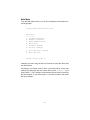
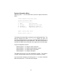
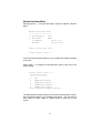
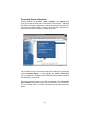
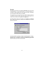
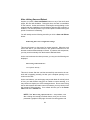
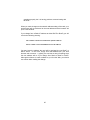
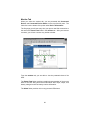
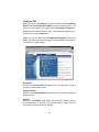
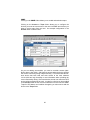
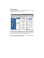
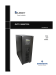
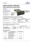
Intellislot SNMP / Web Card
TM
TM
for use with the PowerSure, GXT & Nfinity UPS
®
User Manual
English
TABLE OF CONTENTS
INTRODUCTION ..................................................................................... 1
About this User Manual ..................................................................... 1
About the Quick Start Guide ............................................................. 1
About the Text Formatting ................................................................ 1
Introduction ....................................................................................... 2
INSTALLATION ...................................................................................... 5
Installing the Card ............................................................................. 5
Connecting the Card to the Network ................................................. 5
Configuring the Card ......................................................................... 6
SERVICE TERMINAL ............................................................................. 7
Opening a Service Terminal Connection .......................................... 7
Main Menu ........................................................................................ 9
System Information Menu ............................................................... 10
Network Interface Menu .................................................................. 11
SNMP Communication Menu .......................................................... 13
Web Server Menu ........................................................................... 16
Firmware Updates Menu ................................................................. 17
Factory Settings Menu .................................................................... 18
WEB ...................................................................................................... 19
Opening a Web Connection ............................................................ 19
Connected Device Information ........................................................ 21
Security ........................................................................................... 22
Before clicking Save and Reboot .................................................... 23
After clicking Save and Reboot ....................................................... 24
Monitor Tab ..................................................................................... 26
Control Tab ..................................................................................... 28
Configure Tab ................................................................................. 29
Support Tab .................................................................................... 32
SNMP .................................................................................................... 33
APPENDICES ....................................................................................... 35
MultiLink Support ............................................................................ 35
Nfinity™ Support ............................................................................. 37
INTRODUCTION
About this User Manual
Welcome to the User Manual for the Intellislot SNMP/Web Card. This
manual is available from Liebert's web site at www.liebert.com. The most
recent version is always located online and you should consult the Web if
you feel you have an older copy.
About the Quick Start Guide
In the Appendices, you will find a copy of the Quick Start Guide. The
Quick Start Guide ships in the box with the Intellislot SNMP/Web Card
and provides the most important information you need to install and configure of the card. It included with this manual for your reference.
About the Text Formatting
·Whenever a Liebert product is referred to, the product name appears in
Italics.
·Text from Service Terminal screens is shown using Courier.
·Text representing tabs and folders on the Web interface are show in
bold.
·Text that you need to enter from the keyboard is also shown using Courier and the required text is in quotations.
1
Introduction
The Intellislot SNMP/Web Card delivers SNMP (Simple Network Management Protocol) and Web support to the UPS in which it is installed. The
card is designed for use in a Liebert UPS with an Intellislot bay. This
includes the PowerSure Interactive, UPStation GXT, UPStation GXT2U,
and Nfinity.
The Intellislot SNMP/Web Card requires an Ethernet network connection
and supports both 10Mbit and 100Mbit communication speeds and either
half or full duplex.
The Intellislot SNMP/Web Card enables in-band communication via the
Web from computers running web browser software.
The Intellislot SNMP/Web Card enables in-band communication with network management systems (NMS) via SNMP.
The Intellislot SNMP/Web Card integrates with Liebert's MultiLink™ software to provide notification for unattended, graceful operating system
shutdown of PCs, servers, and workstations. MultiLink is available for
most operating systems. For more information on MultiLink and downloadable version of MultiLink software, please visit www.liebert.com.
2
INSTALLATION
Installing the Card
The Intellislot SNMP/Web Card is hot swappable and user-serviceable.
You do not need to turn off the UPS, disconnect any loads, or restart the
UPS to install or remove the card.
CAUTION: The Intellislot Bay is located in close proximity to the
UPS' output and the UPS' electrical receptacles. Whenever possible, you should turn the UPS OFF when installing the card.
To install the card:
1.Locate the Intellislot bay on the back of the UPS. For Nfinity,
use the Intellislot labeled "COM1".
2.Remove the plastic Intellislot cover and save the screws for
Step 4.
3.Insert the Intellislot SNMP/Web Card into the Intellislot bay.
4.Secure the card with the screws you removed in Step 2.
NOTE: The card is powered by the UPS during both normal and
on battery operation. If the UPS is ON, the card will operate normally after a brief boot up period.
Connecting the Card to the Network
To connect the card to the network, simply plug an Ethernet cable to the
RJ-45 connector on the card.
The card supports 10Mbit and 100Mbit communication speeds at either
half or full duplex. The card ships from the factory in an auto-sensing
mode. In this mode, the card works to negotiate the optimal setting for
your network environment. To turn off the auto-sensing mode and force
the card's communication speed or duplex setting, you will need to open a
Service Terminal connection to the card. Please refer to the Service Terminal section.
5
Configuring the Card
The card ships from the factory with DHCP service enabled. The MAC
address is located on the outside of the box and is also printed on a
sticker affixed to the top of card.
To give the card a static IP address, you will need to open a Service Terminal connection to the card. Please see the following section for more
on the Service Terminal.
6
SERVICE TERMINAL
Opening a Service Terminal Connection
This section covers the Service Terminal in detail. From the Service Terminal, you can configure all settings of the card.
NOTE: You can also configure many of the settings discussed in
this section from the Web. To specify that the card communicate
at either 10Mbit or 100Mbit instead of it trying to auto-negotiate,
you must use the Service Terminal
You access the Service Terminal by opening a direct serial connection to
the Intellislot SNMP/Web Card.
1.Locate the blue serial configuration cable that shipped with the
card.
NOTE: If you have misplaced the cable provided, you
can use a null modem cable with a DB-9F connector at
both ends.
2.Connect one end of the blue serial configuration cable to the DB-9M
serial port on the Intellislot SNMP/Web Card.
3.Connect the other end of the blue serial configuration cable to a terminal or a PC running terminal emulator software, like HyperTerminal™ or ProComm™.
NOTE: If you are using a laptop or PC without any connected serial devices, your active serial port is most likely
COM1. If you have the correct cable and are unable to
open a connection, please confirm that you do not have
a COM port conflict.
4.Use the following communication settings:
BAUD RATE:
DATA BITS:
PARITY:
STOP BITS:
FLOW CONTROL:
9600
8
NONE
1
NONE
5. Press "Enter" to see the Main Menu.
7
If you do not see the Main Menu, press "Enter" again several times. If
the Main Menu fails to appear, confirm that the blue configuration cable is
installed properly, that your PC or terminal COM port is active, and that
you are using the correct communication settings. If, after verifying the
cable and your communication settings are correct you still do not see the
Main Menu, reinstall the card in the Intellislot bay.
NOTE: The card is powered by the UPS. If the UPS is ON, the
card will operate automatically. If you have the cable connected
while inserting the card, you will see initialization text scroll on
your screen. If the card has already been powered, you will not
see this information.
8
Main Menu
From the Main Menu screen, you will find configuration information functionally grouped.
Liebert Network Interface Card
Main Menu
---------1: System Information
2: Network Interface
3: SNMP Communications
4: Web Server
5: Firmware Updates
6: Factory Settings
q: Quit and abort changes
x: Exit and save
Please select a key ?>
Changes you make using the Service Terminal will only take effect after
the card reboots.
Accordingly, you always need to return to the Main Menu screen after
making any change(s) and then select either option "q" or "x". If you
select option "q" your changes will be aborted and the card will retain its
previous settings. If you select option "x" the card will reboot and restart
with your changes.
9
System Information Menu
Selecting option "1" from the Main Menu opens the System Information
Menu.
Liebert Network Interface Card
System Information Menu
-----------------------1: Name
Data Room UPS
2: Contact
Network Services x100
3: Location
Building 2, Floor 4
4: Description
Supporting Main Server
<ESC>: Cancel menu level
Please select a key ?>
The System Information Menu contains four user-defined data fields. The
Service Terminal will report Uninitialized where you have not
entered personalized data. The System Information Menu allows you to
enter useful location and contact information. The data in these fields is
available via SNMP and is presented in the support tab on the Web page.
A typical configuration includes:
Selecting option "1" to assign a name to the UPS.
Selecting option "2" to assign an administrative contact
Selecting option "3" to assign location information.
Selecting option "4" to assign a description.
The Name field can be up to 255 characters in length. The Contact,
Location, and Description fields can be up to 64 characters in length.
If you have made a change, you need to press "Esc" to return to the Main
Menu and then press "x" to exit and save changes.
10
Network Interface Menu
Selecting Option "2" from the Main Menu opens the Network Interface
Menu.
Network Interface Menu
----------------------1: Speed/Duplex
Auto
2: Boot mode
DHCP
IP Address
126.4.1.19
Netmask
255.255.255.0
<ESC>: Cancel menu level
Please select a key ?>
From the Network Interface Menu you can configure the Network settings
of the card
Select option "1" to change the communication speed of the card or the
duplex setting.
Please select a key ?> 1
Valid Selections:
-----------------1. Auto
2. 10Mbs/Half Duplex
3. 10Mbs/Full Duplex
4. 100Mbs/Half Duplex
5. 100Mbs/Full Duplex
Select Speed and Duplex Setting:
The Speed/Duplex default setting is Auto and the card attempts to negotiate the optimal setting for your network environment. You can select a
fixed setting for either 10Mbit or 100Mbit speed, at either full or half
duplex.
11
Select option "2" to change Boot mode settings of the card.
Valid Selections:
-----------------1. Static
2. BootP
3. DHCP
Select Boot Mode:
Your Boot mode setting options are Static, BootP, and DHCP. The card
ships from the factory with DHCP service enabled. DHCP allows the card
to obtain an address dynamically from a DHCP server on your network.
The card also supports BootP dynamic configuration. If you are using
DHCP or BootP you may find want to configure your DHCP or BootP
server with the MAC Address of the card so that the server always
assigns the card a specific address. The MAC Address is printed on a
sticker affixed to the top of the card.
To assign the card a fixed IP address, you need to change the Boot mode
to Static and then provide an IP Address, Netmask, and Default Route.
Network Interface Menu
----------------------1: Speed/Duplex
Auto
2: Boot mode
Static
3: IP Address
126.4.1.102
4: Netmask
255.255.255.0
5: Default Gateway 126.4.1.1
If you have made a change, you need to press "Esc" to return to the Main
Menu and then press "x" to exit and save changes.
12
SNMP Communication Menu
Selecting Option "3" from the Main Menu opens the SNMP Communications Menu.
Liebert Network Interface Card
SNMP Communications Menu
------------------------1: Authentication Traps
2: Display/Modify Communities
3: Display/Modify Trap Communities
'no'
<ESC>: Cancel menu level
Please select a key ?>
From the SNMP Communications Menu you can configure the SNMP settings and behavior of the card.
Select option "1" to turn authentication traps on or off. Enter "y" to enable
authentication traps. Enter "n" to disable authentication traps.
Select option "2" to edit the list of devices you want to have access to the
card via SNMP.
Display/Modify Communities Menu
-------------------------------1:
126.4.1.100
write
MyCommunity
<ESC>: Cancel menu level
<a>dd <d>elete <e>dit
Complex lines allowed. e.g.
<a 198.1.1.1 write public> ?>
The options "a" "d" and "e" allow you to manage your list of network
devices with access to the card. These options can be used as a com13
plex instruction to add a single device, specify read/write access rights,
and designate the Community String. For, example, entering:
"a 126.4.1.200 read NewCommunity"
adds device 126.4.1.200 to the community list. The menu will update:
Display/Modify Communities Menu
-------------------------------1: 126.4.1.100
2: 126.4.1.200
write
read
MyCommunity
NewCommunity
<ESC>: Cancel menu level
<a>dd <d>elete <e>dit
As you are adding communities, you need to consider access rights.
Notice above, that 126.4.1.100 has write access when the device passes
the correct Community String of MyCommunity. This means that this network device has both read and write access to the card, whereas
126.4.1.200 has only the ability to read information when providing the
correct Community String. Devices with write access can control the UPS
and reconfigure settings of the card. In order for a device you have added
to the Communities Menu to also receive notification from the card via
SNMP Traps for UPS alarms and condition changed, you also need to
add the device to the Trap Communities Menu. See below for details.
Select option "3" to edit the list of devices you want to receive traps from
the card via SNMP.
Display/Modify Trap Communities Menu
------------------------------------1:
126.4.1.100
MyCommunity
<ESC>: Cancel menu level
<a>dd <d>elete <e>dit
Complex lines allowed. e.g.
<a 198.1.1.1 public> ?>
The options "a" "d" and "e" allow you to manage you list of network
devices that will receive SNMP Traps from the card. These options can
14
be used as a complex instruction to add a single device and designate the
Community String. For, example, entering:
"a 126.4.1.200 NewCommunity"
adds device 126.4.1.200 to the trap community list. The menu will update:
Display/Modify Trap Communities Menu
------------------------------------1:
2:
126.4.1.100
126.4.1.200
MyCommunity
NewCommunity
<ESC>: Cancel menu level
<a>dd <d>elete <e>dit
It is important to remember that you will often need to add a network
device to both the Communities Menu and the Trap Communities Menu
for your SNMP implementation to work as designed.
If you have made a change, you need to press "Esc" to return to the Main
Menu and then press "x" to exit and save changes.
15
Web Server Menu
Selecting Option "4" from the Main Menu opens the Web Server Menu.
Web Server Menu
---------------1: Web Server
'enabled'
2: Change Username/Password
<ESC>: Cancel menu level
Please select a key ?>
From the Web Server Menu you can enable/disable the Web functionality
of the card and edit the User Name and Password, which regulate access
to the Web control and configuration tabs.
Select option "1" to turn the entire Web Server ON or OFF.
NOTE: If you select disabled, the card will be totally inaccessible
from the Web, although it will continue to operate as an SNMPonly agent.
Select option "2" to edit the User Name or Password that must both be
entered correctly to control the UPS or to change configuration settings of
the card from the Web.
The factory default User Name is “Liebert” and the Password is “Liebert”.
Because this is a well-known username and password, you should
change it as soon as possible. You can also change the User Name or
Password from the Web.
From the service terminal, you do not need to know the current User
Name or Password to make a change.
NOTE: When changing the Username of Password from the Service Terminal, it is possible to leave either field blank. If you omit
either the Username or Password field, the Service Terminal will
accept the input but it will set the response to the default of Liebert.
If you have made a change, you need to press "Esc" to return to the Main
Menu and then press "x" to exit and save changes.
16
Firmware Updates Menu
Selecting Option "5" from the Main Menu opens the Firmware Updates
Menu.
Firmware Updates Menu
---------------------1: Initiate XMODEM session...
<ESC>: Cancel menu level
Please select a key ?>
From the Firmware Updates Menu you can reload the firmware of the
card. Please consult the instructions you downloaded or received with
you new firmware version.
17
Factory Settings Menu
Selecting Option "6" from the Main Menu opens Factory Settings Menu.
Factory Settings Menu
---------------------1: Reset to Factory Defaults
Manufacture Date
OCT 27,2000
MAC Address
00-00-68-16-00-03
Serial Number
415981G101D2000OCT270003
<ESC>: Cancel menu level
Please select a key ?>
The Factory Settings Menu displays information you may be asked by
Liebert Technical Applications Support and is the only electronic place
you can access the MAC address on demand. From the menu, you also
have the option of resetting all the settings of the card the factory default.
Selecting "1" will likely cause the card to be inaccessible from the network
so its use should be applied with caution.
If you have made a change, you need to press "Esc" to return to the Main
Menu and then press "x" to exit and save changes.
18
WEB
Opening a Web Connection
This section explains the Web interface in detail. From the Web, you can
monitor and control the UPS in which the card is installed. You can also
configure many settings of the card.
NOTE: To specify that the card communicates at either 10Mbit or
100Mbit, instead of it trying to auto-negotiate, you must use the
Service Terminal.
You access the Web Interface of the Intellislot SNMP/Web Card by opening a direct web browser. The card utilizes functionality of Microsoft®
Internet Explorer™ 5.0 or higher. Whenever possible, you should use the
latest copy of IE.
1. Open Internet Explorer.
2. Enter the IP address or hostname of the card in the address line
of your browser.
The first page you will see every time you open a new Web connection to
the card is the Power Flow folder in the monitor tab. After your browser
connects, you will see a screen very similar to below:
19
You will notice that information on the Web page is grouped in Tabs and
Folders. The card organizes similar information together in folders, and
similar functions in tabs.
Tabs: Across the top of the screen are four tabs: monitor, control, configure, and support. As the tab names suggest, different information is presented and different operations are available
to you under each tab.
Folders: Within each tab, you will see a different list of folders on
left pane of your screen. Here, display, control, and configuration
information is grouped logically. If, for example, you click the
Input folder under the monitor tab, you will see only information
about the UPS' input power.
20
Connected Device Information
Clicking between the monitor, contol, configure, and support tabs
gives you access to folder lists on the bottom of the left pane. Although
the folder list changes, depending on the tab selected, the top portion of
the left pane remains constant. In the top of the left pane, summary network and connected UPS status is always presented.
The IP address of the card and the Liebert UPS model type is presented
under Connected Device:. In this example, the Intellislot SNMP/Web
Card is installed in a UPStation GXT 700VA UPS and has been assigned
the IP address, 126.4.20.92.
The current operating state of the UPS is presented under Connected
Device Status: along with the most serious UPS alarm, if one is present.
For our example above, the UPS is operating normally with good utility
power.
21
Security
By opening a connection to the Intellislot SNMP/Web Card, you are able
to do three things. You can monitor the UPS. You can also configure, or
reconfigure, network settings and access rights of the card. And finally,
you can control the UPS in which it is installed.
The card allows any user with access to the network segment on which it
is installed to monitor the UPS. This means anyone on the segment can
view the entire contents of the monitor and support tabs.
The card restricts access to the folders in the control and configure
tabs. When a user clicks on a folder, the are prompted to for a User
Name and Password.
The factory default User Name is "Liebert" and the Password is "Liebert".
Because this is a well-known username and password, you should
change it as soon as possible. If you have not made this change from the
Service Terminal, you can do so from the Web.
22
Before clicking Save and Reboot
Just as you discovered when using the Service Terminal, every time you
make a configuration change, the card must reboot for that change to
take effect. Making changes from the Web is the same. As you navigate
between the card's web pages, you will notice that configuration screens
include buttons with text Save and Reboot.
As an example, the screen shot below shows the edit fields available
under the configure tab when you select the Network folder:
When you click any of the web page Save and Reboot buttons, the card
saves any changes you have made and then restarts. During this time,
the card is unavailable on the network. When this process begins, your
web browser may be instructed to open a new page.
23
After clicking Save and Reboot
Anytime you press a Save and Reboot button on any of the card's web
pages, the card will reinitialize. During this time, the card is unavailable
on the network. As the card reboots, it first begins communicating on the
network and then establishes communications with the UPS in which it is
installed. The card will present to you some helpful information during the
period of time that it is restarting.
You will usually see the following text after you click a Save and Reboot
button:
Redirecting due to user configuration change!
This text will remain on the screen for several seconds. When the card
serves this text to your web browser it also passes instructions for the
browser to wait and then attempt to refresh. If, however, this text persists,
you may need to manually click the browser's Refresh button.
As the card continues the reboot process, you may see the following text
displayed:
Discovering connected device...
Last updated: Monday ...
This text is shown after the card has successfully connected to the network and is operating normally, but has yet to complete opening a connection to the UPS.
As the card reboots, your active page may remain blank for a brief period
of time, your web browser may give an unable to connect warning, or it
may continue to display one of the messages above. Due to some timing
issues with networks and static nature of browsers, you may need to click
the browser's Refresh button. Your refresh will take you to the Power
Flow folder in the monitor tab.
NOTE: If the “Discovering connected device...” text persists, even
after clicking the browser's Refresh button, and you are never
presented a graphical UPS page, the card is receiving power and
24
operating properly but it is having problems communicating with
the UPS.
When you make changes to the network address setting of the card, your
web browser will be redirected to the new address and the browser will
open a new window.
If you change from a Static IP address to either DHCP or BootP, you will
receive the following warning.
The card has rebooted to an unknown dynamic address!
Please consult a network administrator for the address!
You may know the address the card will be assigned by your BootP or
DHCP server. In this case, simply enter that address into your web
browser and reconnect. Logically, the card has no way of knowing what
the new address will be if you change from Static to BootP or DHCP.
Although this feature is made available to you from the Web, you should
use caution when making the change.
25
Monitor Tab
When you select the monitor tab, you are presented with Connected
Device: and Connected Device Status: on the top of the left pane. The
folder list is at the bottom of the pane under Device Information:.
The first page you will see every time you open a new Web connection to
the card is the Power Flow folder in the monitor tab. After your browser
connects, you will see a screen very similar to below:
From the monitor tab, you are able to view the parametric data of the
UPS.
The Power Flow folder provides a graphical representation of the current
state of the UPS along with useful information about input, output, and
battery voltages as well as battery runtime information.
The Alarm folder provides a list or any present UPS alarms.
26
Clicking on the Battery, Output, Input, Bypass (not supported in PowerSure Interactive), or Internals folder replaces the summary data presented on the graphical power flow pane with a tabular view of the
complete list of data points reported by the UPS. Clicking on the Input
folder presents a screen similar to:
In the tabular view data, like input voltage, that changes over time is
grouped as a Parameter. Values, which are known to the UPS, like nominal input frequency, are reported in Information. Finally, condition
parameters, like utility failed, are together in a table labeled, Condition.
The list of data in each of these sections and folders varies across UPS
product lines and sizes and will change depending on the UPS in which
you have installed the card.
27
Control Tab
When you select the control tab, you are presented with Connected
Device: and Connected Device Status: on the top of the left pane. The
folder list is at the bottom of the pane under Control Operations:.
As detailed in the Web Security section, a Username and Password protect the folders in the control tab.
From the control tab you can do things like turn the UPS' output ON or
OFF. Each folder represents a different control behavior and this list will
vary across UPS product lines and sizes.
28
Configure Tab
When you select the configure tab, you are presented with Connected
Device: and Connected Device Status: on the top of the left pane. The
folder list is at the bottom of the pane under Configuration Categories:.
As detailed in the Web Security section, a Username and Password protect the folders in the configure tab.
When you click on a folder under Configuration Categories: you will be
able to edit network and device settings, including SNMP community lists.
The folder list is shown below:
Device Info
Clicking on the Device Info folder allows you to edit the Name, Contact,
Location, and Description fields.
Factory Defaults
Clicking on the Factory Defaults folder allows you to reset the card to the
factory settings.
Network
Clicking on the Network folder allows you edit the IP address, Subnet,
and Default Route of the card. You are also able to change the boot
mode setting of Static IP, DHCP, or BootP.
29
SNMP
Clicking on the SNMP folder allows you to enable authentication traps.
Clicking on the Access or Traps folder allows you to configure the
devices you want to have access to the card via SNMP and devices you
want to receive traps from the card. An example configuration in the
Access folder is shown below:
As you are adding communities, you need to consider access rights.
Notice above, that 126.4.1.100 has write access when the device passes
the correct Community String of MyCommunity. This means that this network device has both read and write access to the card, whereas
126.4.1.200 has only the ability to read information when providing the
correct Community String. Devices with write access can control the UPS
and reconfigure settings of the card. In order for a device you have added
to the Access folder to also receive notification from the card via SNMP
Traps for UPS alarms and condition changeds, you also need to add the
device to the Traps folder.
30
Users
Clicking on the Users folder allows you to edit the Username or Password
that must both be entered correctly to control the UPS or change configuration settings of the card from the Web.
The factory default User Name is “Liebert” and the Password is “Liebert”.
Because this is a well-known username and password, you should
change it as soon as possible. You can also change the Username or
Password from the Service Terminal.
From the Web, you need to know the current Username and Password to
make a change.
Web
Clicking on the Web folder allows you to modify the Web browser refresh
rate. Due to the static nature of the Web, the card instructs your Web
browser to refresh many areas of the card's web page at a specific interval.
31
Support Tab
When you select the support tab, you are presented with Connected
Device: and Connected Device Status: on the top of the left pane. A
single device list is at the bottom of the pane under Support:.
The support tab displays the Name, Location, and Description fields as
well as relevant contact information for Liebert Technical Applications
Support team.
32
SNMP
The Intellislot SNMP/Web Card utilizes a SNMPv1 agent and is MIB-II
compliant. The card supports the open standard UPS MIB, RFC1628,
and augments needed functionality in the proprietary Liebert Global Products MIB. A copy of the Liebert Global Products MIB on CD is included in
the box with the card.
33
APPENDICES
MultiLink Support
The most frequently asked question about configuring MultiLink to monitor a SNMP device, like the Intellislot SNMP/Web Card, across the network is, what community string do I use?
NOTE: Use the community string “LiebertEM” for MultiLink.
Configuring for MultiLink support from the Service Terminal
From the Main Menu, select option "3" for SNMP Communications Menu.
In order for MultiLink to monitor the card, the network address information
of the machine on which MultiLink is installed needs to be added to both
the Display/Modify Communities and the Display/Modify Trap Communities.
As an example, you have installed MultiLink on a PC and you will monitor,
across the network, the Intellislot SNMP/Web Card you are now installing.
Your PC has the IP address of 126.4.1.1.
·Select option "2" from the SNMP Communications Menu and
add 126.4.1.1 with the community string “LiebertEM”.
·Select option "3" from the SNMP Communications Menu and
add 126.4.1.1 with the community string “LiebertEM”.
If you have made a change, you need to press "Esc" to return to the Main
Menu and then press "x" to exit and save changes.
Adding to both the Communities list and the Trap Communities list is necessary for MultiLink to work properly.
Configuring for MultiLink support from the Web
Open a web connection to the Intellislot SNMP/Web Card. Click on the
Configure tab. In order for MultiLink to monitor the card, the network
address information of the machine on which MultiLink is installed needs
to be added to both the Access and Traps folders.
35
As an example, you have installed MultiLink on a PC and you will monitor,
across the network, the Intellislot SNMP/Web Card you are now installing.
Your PC has the IP address of 126.4.1.1.
·Select option "2" from the SNMP Communications Menu and
add 126.4.1.1 with the community string “LiebertEM”.
·Select option "3" from the SNMP Communications Menu and
add 126.4.1.1 with the community string “LiebertEM”.
36
Nfinity™ Support
The Intellislot SNMP/Web Card presents additional information on the
Power Flow folder when installed in a Nfinity.
Because the Nfinity is a redundant and scalable UPS, it is important to
know exactly what is installed in its bays. The additional Power Flow
table shows the maximum VA rating of the Nfinity frame along with information about installed Control, Power, and Battery modules.
You will also find Nfinity-specific parameters used for SNMP alarming and
status in the Liebert Global Products MIB.
37
Intellislot SNMP / Web Card
TM
TM
for use with the PowerSure, GXT & Nfinity UPS
®
The Company Behind the Products
With over a million installations around the
globe, Liebert is the world leader in computer
protection systems. Since it’s founding in
1965, Liebert has developed a complete range
of supportand protection systems for sensitive
electronics:
•
•
•
•
•
Environmental systems: close-control air
conditioning from 1.5 to 60 tons.
Power conditioning and UPS with power
ranges from 250 VA to more than 1000
kVA
Integrated systems that provide both
environmental and power protection in a
single, flexible package.
Monitoring and control - from systems of
any size or location, on-site or remote.
Service and support through more than
100 service centers around the world,
and a 24/7 Customer Response Center.
While every precaution has been taken to
ensure accuracy and completeness of this literature, Liebert Corporation assumes no
responsiblity and disclaims all liability for damages resulting from use of this information or
for any errors or omissions.
© 2001 Liebert Corporation.
All rights reserved throughout the world. Specifications subject to change without notice.
® Liebert and the Liebert logo are registered
trademarks of Liebert Corporation. All names
refered to are trademarks or registered tradmarks of their repective owners.
SL-52610 (1/01) Rev. 0