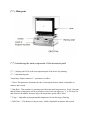
1
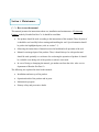
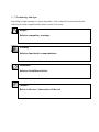
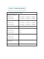
KOUSHA FAN PARS Engineering and Manufacturing Central Office Address: Islamic republic of Iran, shahrake-e-gharb, Farahzadi Blvd., next to Atieh Hospital, Sepehr street, No. 63 Telephone number: (+99)11- 99546963-4 (+99)11-61936 (Special line) Fax number: (+99)11-99541339 E-mail: [email protected] [email protected] (After sales service unit) Factory Address: Tehran-Qom (khalj-e-fars) highway, 53th kilometers, Shamsabad industrial town, Phase 5, Sarvestan Blvd., Gol-e-sorkh 9 street, Segment 1351 Telephone number: (+99)11- 34153163 -9 Fax number: (+99)11-34151331 E-mail: [email protected] Website: www.kfp-dental.com In the name of God Dear customer We thank you for your selectivity and trust in purchasing domestically produced products, and we are pleased that after continuous efforts, we have been able to manufacture Preheating Dental Furnace in Iran and put it at your disposal. This product has been designed by our technical and engineering team of experienced and committed people in the fields of mechanical, electronics and computer engineering, and by utilizing updated technology and building upon on 52 years of experience in manufacturing dental equipment, this product has reached production of export index quality. In designing the product, three principles of accuracy, reliability and safety performance and also being easy to use have been considered, so in order to correctly and completely utilize product features, we ask you to read the instruction manual carefully and if you have any questions or you need more information, contact the after sales services department. User manual is a comprehensive reference for efficient and safe use of the product. Following the instructions of this manual has a great role in reducing consumable costs, avoiding risks and ultimately increasing product life. Instruction manual should always be kept near the product and the user should periodically read it. Please impart us with your constructive guidance, so that we can benefit from your comments, recommendations, and gain knowledge about your needs. With the hope of engrossing your satisfaction, Kousha Fan Pars Engineering and Manufacturing Contents Topic Page Section 1- Introduction (1-1) How to use the manual…………………….......................2 (1-5) Terminology and signs……………………….…...….…….6 Section 5- General information (5-1) Company’s liabilities…………………….……….………...7 (5-5) Guarantee………………………………………….………..7 Section 3- Device introduction (3-1) Main parts………………………………………...…………9 (3-5) Panel description..………………………………...…………9 Section 4- Technical features Section 2- Transportation and installation Section 6- Device applications (6-1) 11 main program planning of furnace …………….………14 (6-5) Idle program………. ……………………………….………14 (6-3) Errors and warning of device …………………….………14 (6-4) Authorized range of parameters………………….………14 Section 7- Safety Section 8- Maintenance (8-1) Clean-up…………………………………………………..53 (8-5) Periodical Cleaning ………………………………………54 Section 1: Maintenance (1-1) How to use the manual This manual presents the instructions about use, installation and maintenance of Preheatung Furnace made by Kousha Fan Pars Co. It should be noted that: The product should be used according to the instructions of this manual. Thus, all parts of it should be read carefully before starting and installing the tool. Special attention should be paid to the highlighted parts. (refer to section 5-1). Observing the instructions of manual assures the health and safe operation of the tool. Manual is an integral part of the product. Thus, it should always be with product and should be used optimally as a reference for use during the operation of product. It should be available even during sale of the product or when it is not used. In case of losing or damaging the manual, get another one from the after- sales service department of Kousha Fan Pars Co. The following are explained in detail in this manual: Installation and start-up of the product Operation details of the product and its parts Maintenance program Primary safety and preventive details (1-1) Terminology and signs Knowledge of signs meanings is of great importance. A list of signs has been introduced in the following for initial recognition and reference to them if necessary. Danger! Indicates compulsory warnings. Warning! Indicates functional recommendations. Forbidden! Indicates forbidden activities. Caution! Refers to the user’s instructions of the tool. Section 2: General information (1-1) Company liabilities Kousha Fan Co. is not liable for any problem involving the following: Failure to follow the instructions of this manual (incorrect use of product), repair by an unauthorized person and part replacement without coordination with after-sales service department, failure due to power fluctuations. (1-1) Guarantee Guarantee of this product includes repairs, supply and replacement. If used appropriately, Kousha Fan Co, guarantee covers all main parts of the device for 1 year. Following cases are not covered by guarantee: power fluctuations incorrect transportation of device inappropriate and frequent use of device despite having obvious flaws not observing the maintenance instructions installation by unauthorized persons any repair or replacement by unauthorized persons. Commutation fees of company representatives to install or repair during guarantee period will be received from buyer at site. User is a representative from the buyer and the necessary instructions should be conveyed to him by the installation team. Generally, activities of a user consist of the following: working with the device according to user manuals, maintenance and periodic inspections, registration and recording incorrect functions and notifying the after the sales unit. Before completing the installation and ensuring the accuracy of productive components, the device is not ready to use. It is strongly recommended that operator should be relatively dominant the content of this manual. The cases of incorrect function in the device operation should be recorded and the after the sales department be notified by operator. Authorized representatives of Kousha Fan pars Co. These persons are endorsed by company to work on the device under any operational circumstances. They are also authorized to do any electrical and mechanical adjustment/repair, maintenance program and authorized parts replacement. Section 3: Device Introduction Preheating furnace is useful for all of thermal operation on dental molded gypsum includes removable prosthesis (cobalt chromium) and fixed prosthesis (porcelain), also in the other laboratory and industrial uses (other than dentistry) are applied. This electric furnace which is able to be planned and computerized control is used in order to plan controllable thermal cycles in thermal speed and adjustable temperature maintenance time and to prevent any unscientific function. In many cases, it can be seen that after the completion of the work, plaster mold cracked or its precision has been missed. This is due to the lack of accurate and programmable furnace, so that thermal shocks hit the mold. By using cylinder furnace, the size and shape of the mold will not be changed either. Advantages of the device: 1. Programmable system and controllable with computer 5. Controlling of temperature, time and speed of heating in 3 steps 3- High speed and precision 4. Set the machine and the program will be performed in an idle time (programming the timer and light up to 111 hours) 2. Equipped with warning system and detector technical violation 6. Equipped with alarm system in different stages of performance 7. Having11 memories for planning and implementing thermal cycles. The information of the system would not be missed in case of power failure and power outages. 8. Showing of working stages with digital display and thermal curves 9. Potential for quick and easy service (5-1) Main parts (3-5) Introducing the main components of the instrument panel (3-5-1) display panel: This is the most important part of the device for planning. (3.5.5) the thermal graph: Temperature Graph contains of 11 parameters as follow: 1. Timer: This parameter determines the time of starting the furnace which is adjustable in minutes and seconds. 5. Heat Rate1: This parameter is warming speed from the initial temperature to Temp1 (It means that the furnace temperature will be increased at a rate of several degrees in ° C or F in min.) So that whatever the number becomes larger, the temperature speed will be faster. 3. Temp 1: Adjustable and programmable temperature for the first stage of heating 4. Hold Time 1: The duration of stop at temp1 which is adjustable in minutes and seconds. 2. Heat Rate5: This parameter is the rate of heating the furnace temperature from Temp1 to Temp5. 6. Temp 5: programmable temperature for the second stage of heating 7. Hold Time 5: The duration of stop at temp5 8. Heat Rate3: This parameter is the rate of heating temperature of furnace from Temp5 to Temp3. 9. Temp 3: programmable temperature for the third stage of heating 11. Hold Time 3: Duration of stop at temp3 (5.1.5) function keys: POWER: To connect and disconnect the electric current. (beside the device) ON / Off: The ON key is to turn on and the Off key is to turn off the device. C / F: To convert temperatures from Celsius to Fahrenheit and vice versa. PROGRAM NUMBER: To select the program number from 1 to 9. PROGRAM EDIT: To view the parameters of inside the program and to change and modify them. CLEAR: To erase the wrong values that they have been entered by mistake and to be used to cut the sound of the alarm. Key numbers: These keys are used to enter numbers and the parameter values. ENTER: To record the entered numbers and parameter value of the programs. TIME: To display the remaining time of time parameter that is running. IDLE: To select the IDLE program. IDLE program is an adjustable program that is configured to heat the furnace. TONE: To enable and disable the Beep sound keys. (5-1-6) Device Monitors: Graphic Monitors: Actually, this curve is a thermal graph at three stages. The process of planning and executing a thermal cycle (heat functions) on the monitor (by LED lights) is shown. Digital Monitors: digital monitors on the left side are to display the values of temperature, time and speed of warming. And monitor on the right side are to display the status of the furnace, number of programs, types of errors or defects (alarms). Section 4: Technical Specifications Technical specifications of the device Dimensions of the Device Cylinder Furnace 1 38 cm (width) * 38 cm (Depth)* 48 cm(height) Cylinder Furnace II 41 cm (width) * 43 cm (Depth)* 22 cm(height) Chamber dimensions: Cylinder Furnace 1 16 cm (width) * 16 cm (Depth)* 11 cm(height) Cylinder Furnace II 51 cm (width) * 53 cm (Depth)* 12 cm(height) Maximum Temperature: 1121 ◦ C (5111 F) Net Weights Cylinder Furnace 1 52 Kg Cylinder Furnace II 36 Kg Cylinder Numbers Cylinder Furnace 1 4 Cylinder Furnace II 6 Maximum power consumption: Functional Voltage 1811 w 511-541 V- AC 21/61 Hertz Section 5: Transportation and installation Upon receiving the product, make sure it is intact. If there is any damage or shortage of parts, inform Koosha Fan Pars Company and its carrier. It is recommended that the original box is kept because it is needed for transporting the furnace safely. Also the box ensures the claim that a safe box has been used during transporting which prevents damage to the device. Installation and Set up the Device 1. Take out the device carefully from its package. To do this, all of the surrounding protectors (EPS) are removed. Then, by taking the "bottom" of the furnace bring it out. Put it on the quite stable, flat and standard laboratory table. It is better to be a minimum distance of 51 cm empty around the furnace. Note that the base or the surface of the table should not be made of metal. If the base of the table has been made of metal and is in contact with the ground. There will be a risk of electric shock. So make sure your furnace is placed on a wooden table or fiberglass one. 5. Connect the power cord on the back of device to a power source of 551 volts. 3. If you use a protection transformer and voltage stabilizer, connect Electric furnace transformer cable to at least 1.2 KW and connect the transformer to the main source. Otherwise, connect the cable directly to independent and secure socket. Your supply power cable and the internal wiring of the laboratory should have the ability to provide the flow of 2 amps. If you are not sure to the wiring of your laboratory use a stabilizer. 4. Power key has been located on the back of the furnace; and by changing its status the system automatically will be tested and checked and after a few seconds the monitor will show the current temperature. If the aforementioned operation is correctly performed, setup of the furnace will be successfully completed and the device is ready to work. Some important points: 1. Put the device in dry and warm place. It should be at least in distance of 52 cm to the nearest wall. 5. Make sure of the resistance of surface below the device against the heat. The sensitive surfaces to heat may lose its color by heating. 3- The wire (Earth) of the device must be connected to AC. (when there is not earth well, the earth wire of the device can be connected to the nearest heater tube (if it is made of metal) or water tube (if it is made of metal)). 4. Prevent the device from direct sunlight. 2. Do not put objects or flammable substances next to the device. 6. While the device is working, do not put any object on the firing chamber. 7. Put the device in an appropriate place in order to prevent any problem in turning on and off the device. 8. The device is designed for indoors usage. 9. The permissible environmental conditions: temperature 12-41 ° C (29 ° F to 114 ° F), with a maximum rate of 727 humidity. Section 6: Device application (4.1) Definition of 13 functional program Put the rings inside the furnace. Note: rings or cylinders or any substances or objects that you put in the furnace chamber, should not be too near or clung to the inside body of thermal chamber (element wires). Press the POWER button to turn on the device. As mentioned before, SUNNY THERM (cylinder) is able to define and store ten independent programs. For programming of each of ten programs, please perform these stages as follow: Before programming, the furnace should be at normal mode. So the right side monitor shows the word’’ Idle’’ and the left one shows the temperature of the furnace. For this purpose only click STOP button. - Click on Key PRG NO once Enter desired program number (1-9) by the number keys - Click on key PRG EDIT button By chart or graphic display, insert thermal cycle’s stages as following. TIMER: This parameter is used to activate the device timer. This parameter is based on time (hours & minutes). It can be programmed for maximum 111 hours (99:29). It means that after passing a preset time, the furnace will be automatically activated then will do the other steps. So enter the desired time and then press ENTER key. Note: If you want to start the furnace immediately, enter zero for this time HEAT RATE 1: This parameter refers to the rate of heating of furnace to reach the first temperature (STAGE 1). The furnace temperature will be increased at a rate of several degrees in ° C or F in min.) . The maximum permissible value for this parameter is 18 ° C or 64 ° F and at least one degree in a minute. Use the number keys to adjust the Parameter and then press ENTER. Note: The actual Heat Rate is achieved through the dynamic structure of Muffle and the AC level. With the current dynamics of the furnace and 551V electricity, the maximum Heat Rate up to temperature of 211 C is about 18 C per minute and up to 811 C is about 11 C to per minute and above the 811 C is about 2 C per minute. STAGE1: It is the temperature of the first stage. For example, enter 311 ° C and then click ENTER. HOLD TIME 1: Duration of stop at the first stage that is adjustable from 1 to 1:31 (GMT). For example, for drying the cylinder plaster enter 41 minutes. HEAT RATE 1: It is the speed of heating the furnace for increasing the temperature from the first heat to the second heat which is in range of 1 to 18 ° C. STAGE 1: It is the temperature of the second stage. Most of the time, it is used for removing wax (Burn out). For example, enter 211 ° C. HOLD TIME 1: Duration of stop at the second stage. For example, enter 42 to 61 minutes for duration of furnace stop at second heat. HEAT Rate 5: It is speed of heating the furnace for increasing the temperature from the second heat to the third heat. For example, enter 11. STAGE 5: It is the final temperature and is for doing the PRE HEATING, therefore increase the temperature for performing CASTINIG. For example enter 911 ° C. HOLD TIME5: Duration of stop at the last stage. For example, enter duration of 31 minutes (11:31). Now, the programming has been done and by clicking the Start button it can be run automatically. If you look at the left side of the graph, you can see that by implementing each phase of the program, a small flicker of lights show the status and stage of the running program. For example, if the furnace is warming to reach Stage1, a small light blinks Heat Rate1. After reaching the final stage STAGE3 temperature and elapsing Hold Time3, for 11 seconds the alarm is heard, it shows that the work is ready. Therefore, for using the cylinder and performing CASTING, furnace temperature will be automatically on the final heat for 61 min in order to let the operator enough time to perform the operation, in this while and every 12 minutes a voice will be heard and after passing 61 minutes the light of Cycle Complete turns on and the furnace temperature starts cooling down. It should be noted that the final stage of 61 minutes can be hindered and stopped by pressing the Stop button. In order not to use the first and second stage of the two stages zero can enter numbers As a result, the furnace will work with the third stage. Therefore, in the third step should be taken STAGE 3 However, the parameters of both the first and second zero can be entered. (4-1) Idle program This program is for heating the furnace temporary or drying the Muffle of device. For this purpose, it is sufficient to follow the blow: The word Idle means unemployment and it is used for keeping warm the furnace in the time of unemployment. The duration of implementing this program completely is 11 minutes. For furnace planning in Idle phase, first press the key Idle and then by pressing PRG EDIT key, it goes into the memory. Please enter the temperature (up to 1111 ° C). Then press ENTER button to let your number enter into the memory and to run by pressing the key STRAT. Note: The speed of heating the HEAT RATE of this program has been set based on the maximum capacity of the furnace. Just press the STOP button to end the IDLE. (4-5) Errors and Alarms of the System: Note: the operating and programming errors always are displayed in your device as Err, but, technical defects along with the sound of the alarm and AL words are displayed on the screen. (4-5-1-) Announced Errors during Programming: ERR 1: If you do not register the program and want to run it, this message appears. ERR 1: If you assign a number for a parameter that is not in the range of furnace operation, by pressing the ENTER key (to record it), this massage will be displayed and the number will not be accepted. To avoid facing with Error 2, the entered numbers and parameters should be in authorized range which is mentioned in listed on page 22. In case of error Err2 you can re-enter the correct number and press the Enter key. If you enter the wrong number by mistake, press the Clear key or zero several times, therefore, the wrong number will be deleted. t If press CLEAR key several times, you can reversely move on the parameters curve of the program which is being edited. The reverse of this action can be done by pressing the STEP key. (4-5-1) Announcing alarms during operation: T-C: At the time of happening failure in thermocouples or lack of proper connection in connector wires of thermocouples occurs. nUFL: occurs at the time of muffle burning or disconnection in the connector wire of thermocouple. (4-6) Authorized range of the parameters As it was noted before, the entered values for programming parameters should be within the authorized ranges. They are listed in the table below: Parameter Minimum Maximum Temperature 111 OC 1111 OC (5115O F) Hold Time 1 Timer 1 Heat Rate 1 (111 Hours) 99.29 (111 Hours) 99.29 18 OC 64O F It is obvious that if these ranges are violated, the Err1 will appear on the display and your program will no longer be executable. Section 7: Safety Kousha Fan Pars Co. makes use of high-quality raw materials for advanced production processes to promote the safety level. In addition to this, the device is tested repeatedly before shipment and is provided for the customer after the confirmation of quality control unit. . Before using the machine, be sure about the accuracy of all parts installation. The device should not be used in case of defects. Following these instructions will increase lifetime of the device: - In case of power fluctuations or weak electricity, use an automatic 5.2 KW transformer manufactured by Faratel Co. - It is recommended to use an independent 5 by 5 cable to supply the furnace. - Avoid turning on/off the furnace frequently and in short spans of time. - If the furnace doesn’t turn on for any reason, wait for at least 1 minute, then press the Power button again. - Read the operational instructions of device before using the device. - Technicians and those who are not trained to use this device are not authorized to use it and Kousha Fan Pars Co. won’t be held liable for wrong operation of the device ant resulting consequences. Don’t clean the device with cleaning solutions while it is ON. Remove the rear cord when cleaning the device. Use the common cleaning solutions. Never keep the panel surface wet for more than 1 minute. Section 8: maintenance 9-1) cleaning To keep the device body clean, please use a dry cloth. Wet the cloth with little water or a nongreasy solution, if needed (only do this for body cleaning). Users should make sure the device is kept clean and free of dust water and other unexpected solutions. At the end of each operation and when the device is on OFF mode and stable, cleaning should be done. Only use dry clothes to clean the device. Before cleaning of the external part of the device, always unplug the device. When using the wind (air compressor) for cleaning, please use eye protection and face masks. In these circumstances do not allow anyone to stand near the device, because of the possibility of damage by particle there. (9-1) Periodic Cleaning Inspection and periodic cleaning of the device depends on operation level. It is suggested for user to inform the company experts about the workflow through consultation after installation and learn the appropriate time for inspection and periodic cleaning from them. If user detects any damage or exhaustion during periodic inspections, he/she should contact the after-sales department, so that measures are taken for maintenance and compulsory service. Periodic service should be determined by user and is performed by the after-sales service department. It is suggested that the maximum time interval for periodic repairs be 15 months. If user detects any defects or problems on the device, he/she should place a warning sign on the device to indicate that it is being maintained and it should not be used (EC warning signs can be purchased at the associated stores). Cleaning, periodic maintenance and appropriate use of the device are important factors in lifetime and safety of it. When any defect is seen in the device operation, it is forbidden to use the device before solving that defect. Safety and protective parts of the device should never be removed from the device unless for repair and maintenance purposes. Thanks for your selectivity Kousha Fan Pars Engineering and Manufacturing