
1
PAMSPAN501x
G.SHDSL.bis EFM Gateway User Manual
Version 1.5
RECYCLABLE
PAMSPAN501x G.SHDSL.bis EFM Gateway
Contents:
INSTRUCTION MANUAL .................................................................................................................... 3
1
Introduction................................................................................................................................ 4
1.1
PAMSPAN501x Overview .................................................................................................................... 4
1.2
Features............................................................................................................................................... 4
1.3
Application .......................................................................................................................................... 5
1.4
Specification ....................................................................................................................................... 5
2
Hardware Setup and Startup ..................................................................................................... 7
2.1
Front Panel LED and Rear Panel description .................................................................................... 7
2.2
DSL Connectors Description.............................................................................................................. 8
2.3
Restore Factory Defaults/Reboot Button ........................................................................................... 8
2.4
Parts check.......................................................................................................................................... 9
2.5
Hardware Connection ......................................................................................................................... 9
2.6
Configuration .................................................................................................................................... 10
2.6.1 Before you begin............................................................................................................................. 10
2.6.2 Assigning static Internet information ................................................................................................ 10
2.6.3 Windows ® XP PCs ........................................................................................................................ 11
2.6.4 Windows 2000 PCs......................................................................................................................... 11
2.6.5 Windows Me PCs ........................................................................................................................... 12
2.6.6 Windows 95, 98 PCs....................................................................................................................... 13
3
3.1
Configure the PAMSPAN501x via EmWeb .............................................................................. 15
Accessing EmWeb ............................................................................................................................ 15
3.2
About EmWeb pages ........................................................................................................................ 15
3.2.1 Status Pages .................................................................................................................................. 16
3.2.1.1
System Information................................................................................................................. 16
3.2.1.2
Physical Port .......................................................................................................................... 16
3.2.1.3
Routing Table ......................................................................................................................... 20
3.2.1.4
Network Interface ................................................................................................................... 21
3.2.1.5
Event Log ............................................................................................................................... 22
3.2.2 System Pages ................................................................................................................................ 23
3.2.2.1
Save config ............................................................................................................................ 23
3.2.2.3
Prompt ................................................................................................................................... 25
3.2.2.4
Firmware Update .................................................................................................................... 26
3.2.2.5
Backup/Restore...................................................................................................................... 27
3.2.2.6
Restart ................................................................................................................................... 28
3.2.3 Configuration pages ........................................................................................................................ 29
3.2.3.1
LAN connections .................................................................................................................... 29
3.2.3.1.1 Supporting multi port router ............................................................................................... 33
3.2.3.1.2 Command Line Interface for LAN....................................................................................... 34
1
PAMSPAN501x G.SHDSL.bis EFM Gateway
3.2.3.2
WAN Connection .................................................................................................................... 35
3.2.3.2.1 Command Line Interface for WAN ..................................................................................... 40
3.2.3.3
DHCP Server.......................................................................................................................... 41
3.2.3.3.1 Command Line Interface for DHCP Server ........................................................................ 44
3.2.3.4
DHCP Relay ........................................................................................................................... 46
3.2.3.4.1 Command Line Interface for DHCP Relay.......................................................................... 48
3.2.3.5
DNS Client ............................................................................................................................. 49
3.2.3.5.1 Command Line Interface for DNS Client ............................................................................ 49
3.2.3.6
DNS Relay ............................................................................................................................. 50
3.2.3.6.1 Command Line Interface for DNS Relay ............................................................................ 53
3.2.3.7
SNTP Client ........................................................................................................................... 53
3.2.3.7.1 Command Line Interface for SNTP Client .......................................................................... 57
3.2.4 Advanced Pages............................................................................................................................. 58
3.2.4.1
Security .................................................................................................................................. 59
3.2.4.1.1 Enabling Security .............................................................................................................. 60
3.2.4.1.2 Enabling Firewall and/or Intrusion Detection ...................................................................... 60
3.2.4.1.3 Setting a default Security Level ......................................................................................... 60
3.2.4.1.4 Configuring Security Interfaces.......................................................................................... 60
3.2.4.1.5 Configuring NAT ................................................................................................................ 61
3.2.4.1.6 Configuring NAT global addresses..................................................................................... 62
3.2.4.1.7 Configuring NAT reserved mapping ................................................................................... 64
3.2.4.1.8 Configuring Firewall policies .............................................................................................. 65
3.2.4.1.9 Configuring validators........................................................................................................ 67
3.2.4.1.10 Configuring triggers ......................................................................................................... 68
3.2.4.1.11 Configuring Intrusion Detection Settings .......................................................................... 69
3.2.4.2
IP Routes ............................................................................................................................... 82
3.2.4.3
Bridge .................................................................................................................................... 84
3.2.4.3.1 Spanning Bridge Configuration .......................................................................................... 87
3.2.4.3.2 Interface Configuration ...................................................................................................... 87
3.2.4.4
VLAN ..................................................................................................................................... 91
3.2.4.4.2 Edit untagged Ports ........................................................................................................... 92
3.2.4.4.3 MGMT VLAN Configuration ............................................................................................... 93
3.2.4.4.4 Destination Based Unicast Filtering Entry Configuration..................................................... 93
3.2.4.4.5 Multicast Filtering Entry Configuration................................................................................ 94
3.2.4.4.6 Forward All/Unregistered Configuration ............................................................................. 95
3.2.4.5
SHDSL ................................................................................................................................... 96
3.2.4.6
QoS........................................................................................................................................ 97
3.2.4.6.1 To add a classifier profile................................................................................................... 98
3.2.4.6.2 To add a scheduler for QoS............................................................................................. 100
3.2.4.6.3 Attach a profile to a transport........................................................................................... 104
4
Diagnostic and Troubleshooting .......................................................................................... 107
Appendix A – Acronyms ................................................................................................................ 108
2
PAMSPAN501x G.SHDSL.bis EFM Gateway
INSTRUCTION MANUAL
3
PAMSPAN501x G.SHDSL.bis EFM Gateway
1 Introduction
Thank you for choosing the PAMSPAN501x as your broadband access solution. This
manual will help you with the setup and configuration of your product.
1.1 PAMSPAN501x Overview
The PAMSPAN501x takes advantage of the latest technology - Extended Rate Bonded
SHDSL – opening up unprecedented possibilities for symmetric transmission.
The PAMSPAN501x comes with EFM bonding or ATM m-pair bonding; higher packet
transport allows symmetric data rates of up to 5.69 Mbps, 11.38Mbps, 17.07 Mbps, or
22.76Mbps over standard 2-wire, 4-wire, 6-wire, or 8-wire telephone lines, respectively.
EFM different rates between pair 4:1 means that speed ratio of 4 between the fastest and
slowest link of a group (according to IEEE 802.-2004)
The PAMSPAN501x is a solution that enables enterprise users to enjoy long distance, high
bandwidth and symmetric data transmission.
Distance & Rate relationship Table
26 AWG_ Without Noise _ EFM mode
1-Pair Longest 2-Pairs Longest 3-Pairs Longest 4-Pairs Longest
Line rate (kbps)
reach (feet)
reach (feet)
reach (feet)
reach (feet)
192
18000
18000
18000
18000
256
18000
18000
18000
18000
384
18000
18000
18000
18000
768
16400
16400
16400
16400
2560
11500
11500
11500
11500
3072
10500
10500
10500
10500
3392
10000
10000
10000
10000
3584
9500
9500
9500
9500
3848
9400
9400
9400
9400
4096
9000
9000
9000
9000
5696
7000
7000
7000
7000
1.2
Features
Rate and Reach Improvements
The symmetric transmission rate can be up to 5.69 Mbps, 11.38Mbps, 17.07 Mbps,
or 22.76Mbps over standard 2-wire, 4-wire, 6-wire, or 8-wire telephone lines,
respectively.
Note: When one pair fails while operating in multiple pairs mode, the connection will
still be maintained. The other pairs can still operate at the maximum rates.
4
PAMSPAN501x G.SHDSL.bis EFM Gateway
CO and CPE Mode selectable
Provides point-to-point connectivity
2-wire/4-wire/6-wire/8-wire EFM bonding or ITU-T G.bonding Mode selectable
Offers flexible rate options
Easy Management
Support both web-based GUI and CLI-based management.
Backward Compatible to G.SHDSL (G.991.2)
1.3 Application
1.4 Specification
Standard Compliance
Protocol
ITU-T G.991.2
Support EFM over G.SHDSL.bis and G.SHDSL
Transmission rate up to 5.69 Mbps on 2-wire
Support ATM over G.SHDSL.bis and G.SHDSL
Transmission rate up to 11.38 Mbps on 4-wire
MAC bridging (IEEE 802.3ah-2004 and 802.1D)
Transmission rate up to 17.07 Mbps on 6-wire
PPPoE (RFC 2416)
Transmission rate up to 22.76 Mbps on 8-wire
Support of Annex A, Annex B, Annex F, and
Annex G
RFC 1483/2684 Bridged encapsulation (routing mode
optional)
IP support TCP, RIPv1, RIPv2, UDP, ICMP, ARP
Auto load balancing with bonded pairs
IEEE802.1P Priority Output Queuing
Support point-to-point configuration
IEEE 802.1Q VLAN
Manual or auto rate selectivity
IEEE802.3u Fast Ethernet 100BaseT
Comply IEEE 802.3ah-2004
MAC Filtering
ITU-T G.994.1
QoS support VBR-rt, VBR-nrt, CBR and UBR
5
PAMSPAN501x G.SHDSL.bis EFM Gateway
Maintenance
Firmware upgradeable via FTP or TFTP (optional)
Support Telnet
Support ATM OAM F5 End to End and Segment loop
backs
Statistics on DSL link and data ports
Sys-log
HTTP web downloadable
Support 8 PVCs
NAT/PAT support
DHCP client/server and DHCP relay functionality
Support IGMP Snooping
DMZ support
Support Port-based VLAN
Management
LED
Password protection
PAP and CHAP support
Remote access management via telnet
Hardware Interface
SNMPv1/SNMPV2
Firewall Security
DSL interface: 2/4 wires one RJ-11 jack. 8 wires two
RJ-11 jacks
Ethernet interface: four RJ-45 jack; 10/100BaseT auto
sensing and crossover
AC power adapter (100VAC ~ 240VAC, 50-60Hz)
One craft Interface for local console access (CID)
Packet Filter
Denial of Service
Stateful Packet Inspection (SPI)
Attack Alert and log
Access Control
Real time log
LED indicator; power, DSL links, Alarm, Ethernet ports
and CO/CPE mode
Dimensions & Weight
Dimensions: 35mm(H)×210mm(W)×193mm(D)
Weight: 914g
MIB-II (RFC 1213, RFC 1573)
Web based GUI
Operating Requirements
Command Line Interface (CLI)
Operating temperature: 0C to +50C
Operating humidity: 5% to 90% RH non-condensing
Power Consumption for 2-pair is 5.6W and 4-pair is
5.8W
6
PAMSPAN501x G.SHDSL.bis EFM Gateway
2 Hardware Setup and Startup
2.1
Front Panel LED and Rear Panel description
Following pictures are the front panel of 4-wire and 8-wire PAMSPAN501x respectively.
Figure 2-1 8-wire PAMSPAN501x Front Panel LED
Figure 2-2 4-wire PAMSPAN501x Front Panel LED
1. PWR
Power Indicator
2. DSL
DSL loop
On--- CO
Off--- CPE
Alarm for error
On---Ethernet Link connected
3. CO
4. ALM
5. LAN
Figure 2-3 8-wire PAMSPAN501x rear view
Figure 2-4 4-wire PAMSPAN501x rear view
7
PAMSPAN501x G.SHDSL.bis EFM Gateway
1. DC IN:
Power Adapter Input
2. Reset Button:
Reset device to factory default setting
3. CID:
Connected to PC serial port for console
4. LAN:
Connected to Ethernet Port
5. DSL 1 to 4
Connected to loop 1 to 4
6. FG
Connected to ground wire
2.2 DSL Connectors Description
DSL Connectors on back of the unit, 2 RJ-11 sockets.
DSL
1
2
3 4
RJ-11 uses a 6P4C connector and cable. The cable has 4 wires and we are using them for
2 pairs of DSL connection.
Pin 1
Pin 2
Pin 3
Pin 4
Pin 5
Pin 6
Not used.
Tip for DSL pair 2 or 4.
Tip for DSL pair 1 or 3
Ring for DSL pair 1 or 3
Ring for DSL pair 2 or 4
Not used.
1
2
3
4
5
6
2.3 Restore Factory Defaults/Reboot Button
Press the reset button to reset the PAMSPAN501X to its factory-default settings (the
default configuration file will be uploaded). If you forget your password or cannot access
the device, you will need to reset the device to the default settings. The procedure is as
follows:
1. Power off the modem.
2. Press the reset default button.
3. Power on the Modem, and check the front panel of the modem.
4. When the “CPE LED” blinks rapidly, release the reset button.
(If you press the button for too long, the configuration file recall won't work. This is to
prevent the user from holding the button continuously)
5. The factory defaults should now be recalled. (This is called a "one-time recall")
8
PAMSPAN501x G.SHDSL.bis EFM Gateway
2.4 Parts check
Check the following items in your package. Contact our sales representatives if any item is
missing or damaged.
PAMSPAN501x
RJ-11 Cable
Power Adapter
Support CD
I
RJ-45 Cable
Quick Installation
Guide
Q.I.G
2.5 Hardware Connection
1.
Connect the RJ11 cable supplied to the port marked DSL at the back of the
PAMSPAN501X. Connect the other end of the cable to your SHDSL signal source.
2.
Insert one end of the RJ45 Ethernet cable into one of the LAN ports on the back of the
PAMSPAN501X. Connect the other end of the cable to the Ethernet Network Interface
Card (NIC) in your PC. Up to four Ethernet devices can be connected to the
PAMSPAN501X.
3.
Connect an earth ground to the grounding terminal (marked FG).
4.
Connect the external AC adapter supplied to the DC power outlet on the back of the
PAMSPAN501X. Connect the power supply to your wall outlet or surge protector.
DSL
LAN
FG
CID
RJ45
RJ11
Internet
Switch
or
Hub
9
Reset
DC IN
05-17665
PAMSPAN501x G.SHDSL.bis EFM Gateway
2.6
Configuration
This section provides instructions for configuring your Internet settings to work with the
router.
2.6.1
Before you begin
By default, the LAN port is assigned this IP address: 192.168.1.1. (You can change this IP
address as you need. For example: IP 192.168.1.2 NetMask 255.255.255.0).
Note: In some cases, you may want to assign Internet information manually to some or all of your
computers rather than allow the PAMSPAN501X to do so. See “Assigning static Internet information” for
instructions.
2.6.2
Assigning static Internet information
If you are like most users, you will not need to assign static Internet information to your
LAN PCs. Your ISP automatically assigns this information.
In some cases however, you may want to assign Internet information to some or all of your
PCs directly (often called “statically”), rather than allowing the PAMSPAN501X to assign it.
This option may be desirable (but not required) if:
•
You have obtained one or more public IP addresses that you want to always associate
with specific computers (for example, if you are using a computer as a public web
server). (suggest to delete)
•
You maintain different subnets on your LAN.
Before you begin, be sure to have the following information on hand, or contact your ISP if
you do not know it:
•
The IP address and subnet mask to be assigned to each PC to which you will be
assigning static IP information.
•
The IP address of the default gateway for your LAN. In most cases, this is the address
assigned to the LAN port on the PAMSPAN501X.
•
The IP address of your ISP’s Domain Name System (DNS) server.
On each PC to which you wish to assign static information, follow the instructions on
checking for and/or installing the IP protocol. Once it is installed, continue to follow the
instructions for displaying each of the Internet Protocol (TCP/IP) properties. Instead of
enabling dynamic assignment of the IP addresses for the computer, DNS server and
default gateway, click the radio buttons that enable you to enter the information manually.
Note: Your PCs must have IP addresses that place them in the same subnet as the
10
PAMSPAN501x G.SHDSL.bis EFM Gateway
PAMSPAN501X LAN port. If you manually assign IP information to all your LAN PCs, you
can use the LAN Connections to update the LAN port IP address accordingly.
2.6.3
Windows ® XP PCs
1.
In the Windows task bar, click the Start button, and then click Control Panel.
2.
Double-click the Network Connections icon.
3.
In the LAN or High-Speed Internet window, right-click on the icon corresponding to
your network interface card (NIC) and select Properties. (Often, this icon is labeled
Local Area Connection). The Local Area Connection dialog box displays with a list of
currently installed network items.
4.
Ensure that the check box to the left of the item labeled Internet Protocol TCP/IP is
checked, and click.
5.
In the Internet Protocol (TCP/IP) Properties dialog box, click the radio button
labeled Obtain an IP address automatically. Also click the radio button labeled
Obtain DNS server address automatically.
6.
2.6.4
Click
twice to confirm your changes, and close the Control Panel.
Windows 2000 PCs
First, check for the IP protocol and, if necessary, install it:
1.
In the Windows task bar, click the Start button, point to Settings, and then click
Control Panel.
2.
Double-click the Network and Dial-up Connections icon.
3.
In the Network and Dial-up Connections window, right-click the Local Area Connection
icon, and then select Properties.
The Local Area Connection Properties dialog box displays with a list of currently
installed network components. If the list includes Internet Protocol (TCP/IP), then the
protocol has already been enabled. Skip to step 10.
4.
If Internet Protocol (TCP/IP) is not displayed as an installed component, click
.
5.
In the Select Network Component Type dialog box, select Protocol, and then click
.
6.
Select Internet Protocol (TCP/IP) in the Network Protocols list, and then click
.
11
PAMSPAN501x G.SHDSL.bis EFM Gateway
You may be prompted to install files from your Windows 2000 installation CD or other
media. Follow the instructions to install the files.
7.
to restart your computer with the new settings.
If prompted, click
Next, configure the PCs to accept IP information assigned by the PAMSPAN501X:
8.
In the Control Panel, double-click the Network and Dial-up Connections icon.
9.
In Network and Dial-up Connections window, right-click the Local Area Connection
icon, and then select Properties.
10. In the Local Area Connection Properties dialog box, select Internet Protocol
(TCP/IP), and then click
.
11. In the Internet Protocol (TCP/IP) Properties dialog box, click the radio button labeled
Obtain an IP address automatically. Also click the radio button labeled Obtain DNS
server address automatically.
12. Click
twice to confirm and save your changes, and then close the Control
Panel.
2.6.5
1.
Windows Me PCs
In the Windows task bar, click the Start button, point to Settings, and then click
Control Panel.
2.
Double-click the Network and Dial-up Connections icon.
3.
In the Network and Dial-up Connections window, right-click the Network icon, and
then select Properties.
The Network Properties dialog box displays with a list of currently installed network
components. If the list includes Internet Protocol (TCP/IP), then the protocol has
already been enabled. Skip to step 11.
4.
If Internet Protocol (TCP/IP) does not display as an installed component, click
.
5.
In the Select Network Component Type dialog box, select Protocol, and then click
.
6.
Select Microsoft in the Manufacturers box.
7.
Select Internet Protocol (TCP/IP) in the Network Protocols list, and then click
.
You may be prompted to install files from your Windows Me installation CD or other
media. Follow the instructions to install the files.
8.
If prompted, click
to restart your computer with the new settings.
Next, configure the PCs to accept IP information assigned by the PAMSPAN501X.
12
PAMSPAN501x G.SHDSL.bis EFM Gateway
9.
In the Control Panel, double-click the Network and Dial-up Connections icon.
10. In Network and Dial-up Connections window, right-click the Network icon, and then
select Properties.
11. In the Network Properties dialog box, select TCP/IP, and then click
.
12. In the TCP/IP Settings dialog box, click the radio button labeled Server assigned IP
address. Also click the radio button labeled Server assigned name server address.
13. Click
twice to confirm and save your changes, and then close the Control
Panel.
2.6.6
Windows 95, 98 PCs
First, check for the IP protocol and, if necessary, install it:
1.
In the Windows task bar, click the Start button, point to Settings, and then click
Control Panel.
2.
Double-click the Network icon.
The Network dialog box displays with a list of currently installed network components.
If the list includes TCP/IP, and then the protocol has already been enabled. Skip to
step 9.
3.
If TCP/IP does not display as an installed component, click
.
The Select Network Component Type dialog box displays.
4.
Select Protocol, and then click
.
The Select Network Protocol dialog box displays.
5.
Click Microsoft in the Manufacturers list box, and then click TCP/IP in the Network
Protocols list box.
6.
Click
to return to the Network dialog box, and then click
again.
You may be prompted to install files from your Windows 95/98 installation CD. Follow
the instructions to install the files.
7.
Click
to restart the PC and complete the TCP/IP installation.
Next, configure the PCs to accept IP information assigned by the PAMSPAN501X:
8.
Open the Control Panel window, and then click the Network icon.
9.
Select the network component labeled TCP/IP, and then click
13
.
PAMSPAN501x G.SHDSL.bis EFM Gateway
Note: If you have multiple TCP/IP listings, select the listing associated with your
network card or adapter.
10. In the TCP/IP Properties dialog box, click the IP Address tab.
11. Click the radio button labeled Obtain an IP address automatically.
12. Click the DNS Configuration tab, and then click the radio button labeled Obtain an IP
address automatically.
13. Click
twice to confirm and save your changes.
You will be prompted to restart Windows. Click
14
.
PAMSPAN501x G.SHDSL.bis EFM Gateway
3 Configure the PAMSPAN501x via EmWeb
3.1
Accessing EmWeb
To access EmWeb on the PAMSPAN501x that has been booted with an image containing
a factory default configuration:
1. Attach a PC to one of the LAN interfaces. At your web browser, enter the URL:
http://192.168.1.1
2. If you first time login the EmWeb, you will see a login box is displayed. You must enter
your username and password to access the pages. The default User name/Password as
follows
User Name: admin
Password: admin
3. Click on
3.2
. You are now ready to configure PAMSPAN501x using EmWeb.
About EmWeb pages
EmWeb provides a series of web pages that you can use to setup and configure the
PAMSPAN501x. These pages are organized into three main topics. You can select each of
the following topics from the menu on the left-hand side of the main window:
• Status: information about the current setup and status of the system.
• System: The System section lets you carry out system commands like Event Log,
Firmware Update, Backup/Restore, Save configuration and Authentication.
• Configuration: information about the current configuration of various system features with
options to change the configuration.
The changes made via web pages will immediately reflect in all elements of the network.
The exact information displayed on each web page depends on the specific configuration
that you are using. The following sections give you a general overview of the setup and
configuration details.
-15
PAMSPAN501x G.SHDSL.bis EFM Gateway
3.2.1
Status Pages
The Status homepage contains information about the current configuration of
PAMSPAN501x. It provides an overview of the current image configuration. The page
contains the following sections:
3.2.1.1
System Information
Click System Information on Status menu, and then System information page
will be displayed as shown below:
3.2.1.2
Physical Port
This option allows you to configure the ports available on your PAMSPAN501X,
depending on the type of image that you intend to boot.
Configuring ports
1. From the Status menu, click on Physical Port. The physical ports available on
your device will be displayed.
-16
PAMSPAN501x G.SHDSL.bis EFM Gateway
2. Click on Shdsl. The Shdsl Port Configuration page will be displayed:
3. This page allows you to carry out advanced configuration of your SHDSL
port attributes. From the Shdsl Port Configuration page, click View advanced
attributes. The Shdsl Port Configuration page will be displayed. “Shdsl” is the
default SHDSL port name created in the PAMSPAN501X. You can configure
the SHDSL parameters on this page.
-17
PAMSPAN501x G.SHDSL.bis EFM Gateway
4. In the Unit Id drop-down menu, you can set the device as either CO or CPE,
and then click
to save the settings.
-18
PAMSPAN501x G.SHDSL.bis EFM Gateway
5. To set the PAMSPAN501X to Wire pair mode, click the Wire Mode
drop-down list to select the desired Wire Pair number. After that, click
to
save the settings.
Wire Mode
1-PAIR
2-PAIR
3-PAIR
4-PAIR
DSL Pair to Use
1
1,2
1,2,3
1,2,3,4
Illustration
DSL
1
2
3 4
6. To set the maximum and minimum line rate, enter the Max and Min Line Rate
values (where the values range from 192000bps to 5696000bps) and then click
to save the settings. Once the handshaking process between the STU-R
and STU-C devices is complete, the actual transmission rate will be displayed
in the Current Tx Rate attribute.
7. To configure a specific Ethernet port, click the appropriate port number
(eth1~eth4) in the Physical Port Table and then the Ethernet Port Configuration
page will be displayed:
The page displays the basic port attributes for the Ethernet port on your
PAMSPAN501X.
-19
PAMSPAN501x G.SHDSL.bis EFM Gateway
8. This page allows you to view or carry out advanced configuration of your
Ethernet port attributes. For instance, Click View advanced attributes on Eth1
Port Configuration, and then the Advanced Eth1t Port Configuration page will
be displayed.
Set the Ethernet port as either enabled or disabled via the Admin Status
drop-down list, and then click
to update the advanced configuration, or
to revert to the default advanced configuration settings. Click Return
to basic attributes to return to the Eth1 Port Configuration page.
3.2.1.3
Routing Table
Routing Table is a matrix with a network control protocol, which gives the
hierarchy of link routing at each node.
The Routing Table screen allows you to view the routing table built in the
device.
-20
PAMSPAN501x G.SHDSL.bis EFM Gateway
If to create an IP route, refer to the IP Routes section on Advanced menu.
3.2.1.4
Network Interface
If to view the statistics on Bridge/Router Interfaces, select a specified interface
to invoke the Bridge/Router Interface page.
Following figure shows the statistics on the interface, rfc1483-0.
Click
to get the latest status information for this bridge interface.
-21
PAMSPAN501x G.SHDSL.bis EFM Gateway
3.2.1.5
Event Log
Click on Event Log, the following page is displayed as follows:
This page displays a table containing all configuration errors experienced by
your Router during a current session. 3 types of logs can be selected via select
a log drop-down list.
All Events: Shows all events occurred.
Configuration errors: Shows error messages regarding configuration(s) which
the system DOES NOT allow to change
Syslog messages: Shows all messages regarding system actions other then
Configuration errors.
-22
PAMSPAN501x G.SHDSL.bis EFM Gateway
3.2.2
System Pages
Click on System menu, the following options appear:
The System menu contains options including, Firmware Update, Backup/Restore and
Restart Router, Prompt, Save configuration and Authentication. They will be
introduced in the following sections.
3.2.2.1 Save config
To save your current configuration to Flash ROM:
1. From the System menu, click on Save configuration. The following page is
displayed:
2. Click on
to save your current configuration in the device.
After a short time the configuration is saved and the following confirmation
message is displayed: Saved information model to file //flashfs/im.conf
-23
PAMSPAN501x G.SHDSL.bis EFM Gateway
3.2.2.2 Authentication
This option allows accounts for users who access the PAMSPAN501X to be
administered. Click Authentication via the System menu. The following page will
be displayed:
To creating a new login account
1. Click Create a new user. The following page will be displayed:
2. Enter the desire information details for the new user into the username,
password and comment text fields.
3. Click
. The Authentication page will be displayed. The table now
contains details for the user that has just been created.
-24
PAMSPAN501x G.SHDSL.bis EFM Gateway
To editing/deleting a login account
1. The Authentication page table contains an Edit user hyperlink for each user
account entry. Click a link and the following page will be displayed:
This page allows:
• Details for a specific user account to be updated. Modify the necessary text
boxes then click
.
• A user account to be deleted. Click the Delete this user button.
2. Once a user account has been edited or deleted, the Authentication page will
be displayed and the table will reflect any changes that have been made on the
Edit user page.
3.2.2.3
Prompt
This configuration allows user to configure the prompt name which will be
shown in the CLI prompt. Enter the name you wish to show in CLI prompt and
click
.
-25
PAMSPAN501x G.SHDSL.bis EFM Gateway
3.2.2.4
Firmware Update
This option allows firmware images to be uploaded to the PAMSPAN501X using
HTTP.
1. From the System menu, click Firmware update. The following page will be
displayed:
2. Enter the location of the new firmware image that is to be uploaded, or use
the
button to browse and select the file. Click
.
3. Once the file has been uploaded to the RAM of your device, it is written to
the Flash ROM. A status page will be displayed confirming whether the upload
is complete or indicating how much of the file (in bytes and as a percentage)
has been written to the Flash ROM.
4. Once the file has been written to flash, the Firmware Update page is
refreshed. The page confirms completion of the update and requests that the
PAMSPAN501X be restarted in order to use the new firmware. Click Restart in
the system menu.
Note: Please do not power-off the device while updating firmware or saving the
configuration as this might cause the device to malfunction.
5. After updating the firmware, it is strongly suggested that the device is
restarted and the default configuration is recalled as this will prevent any
incompatible configuration between the former and the current firmware
versions. To do this, check the Reset to factory default settings box on the
Restart page in the system menu.
-26
PAMSPAN501x G.SHDSL.bis EFM Gateway
3.2.2.5
Backup/Restore
From the System menu, click Backup/restore. The following page will be
displayed. This page allows the configuration to be backed up to, or restored
from, another computer.
Backing up your configuration
1. From the Backup Configuration section, click
window will be displayed. Click
. The File Download
. The Save As window will then be
displayed. Select a directory in which to save the backup configuration and click
.
Restoring a configuration
1. In the Restore Configuration section as shown below, click in the
Configuration File text box and enter the network path of the file that is to be
restored. If the path details are unknown, click
using the Choose file window.
-27
and locate the file
PAMSPAN501x G.SHDSL.bis EFM Gateway
2. Click
. The page will be refreshed and a Configuration Restored
message will be displayed giving details of the number of bytes uploaded.
3.2.2.6
Restart
This page allows the PAMSPAN501X to be restarted and has the same effect
as resetting the PAMSPAN501X by pressing the reset button on the hardware.
1. From the System menu, click Restart. The following page will be displayed:
2. Click
to reset the PAMSPAN501X. The Restart page also provides
an option to restart and restor the factory default settings. Check the Reset to
factory default settings checkbox, and then click
. Monitor the console
status output to check the reset progress.
3. After the login and password prompt is displayed, login as usual (with login =
admin, password = admin), and then refresh the browser that is running
EmWeb. The Status page will be displayed and the PAMSPAN501X has been
reset.
-28
PAMSPAN501x G.SHDSL.bis EFM Gateway
3.2.3
Configuration pages
The Configuration menu contains options for configuring features on PAMSPAN501x
including basic LAN and WAN connections and DHCP and DNS settings.
Note: Most of the features contain sensible default settings. You are unlikely to have to
reconfigure every feature included in the Configuration menu. From the left-hand menu
and click on Configuration. The following sub-headings are displayed:
• LAN connections: allows you to edit your LAN port IP address, create and edit a
secondary IP address and create new LAN services.
• WAN connections: allow you to create, edit and delete WAN services.
• DHCP server: allow you to enable, disable and configure your DHCP server.
• DHCP relay: allow you to enable, disable and configure your DHCP relay.
• DNS client: allow you to enable, disable and configure DNS client.
• DNS relay: allow you to enable, disable and configure DNS relay.
• SNTP client: allow you to configure Simple Network Time Protocol at Client side. (Please
point to the SNTP server, contact with your ISP provider.)
3.2.3.1
LAN connections
LAN connections, as shown below, refer to the connection of the customer end,
which using different IP address than WAN.
This option allows you to:
• Configure the LAN IP address and subnet of the default LAN connection to the
PAMSPAN501X.
• Create WAN interfaces: multiple virtual interfaces can be associated with the
existing primary LAN interface.
-29
PAMSPAN501x G.SHDSL.bis EFM Gateway
From the Configuration menu, click LAN connections. The following page will be
displayed:
The service, eth1, is not shown because it has already been created by default,
which user will not be able to delete it. The Creator column shows the method that
the services are being created. By default command, all four ports will be created
from CLI; therefore, it would show CLI under the Creator column.
To delete a service
If users would like to delete a service, simply click the specific port link, such as
“eth3” under Descriptions column, the port deletion page will be displayed as
shown below:
Click
to delete the connection. Once there is a connection
-30
PAMSPAN501x G.SHDSL.bis EFM Gateway
that has been deleted, user will then be able to use
create a service. By clicking
to
, users will be able to select the
type of service that they wish to create as shown below:
By using the web to create a service, it would then show WebAdmin under the
Creator column.
Configuring primary and secondary LAN connections
1. The Default LAN Port section contains two subsections:
a. IP address and subnet mask details for your primary LAN connection. To edit these
details, click
and enter the new primary address details
b. Secondary IP address details. To create/configure a secondary IP address, click in
the Secondary IP Address text box and enter the new address details.
2. Once you have configured the IP address(es), click
button. A message will
be displayed confirming that your address information is being updated. If you have
-31
PAMSPAN501x G.SHDSL.bis EFM Gateway
changed the primary IP address, you may need to enter the new address in your web
browser address box.
To edit IP interface
1.
Click
hyperlink at the bottom of the LAN connections page. The Edit IP
Interfaces page will be displayed as shows below, the user will be able to change or
modify the value of this IP Interface.
Field Definition of IP Interface
Field
Ipaddr
Mask
Dhcp
MTU
Definition
The IP address for this IP Interface
Mask fort this IP Interface
DHCP is a protocol used to obtain IP addresses
and other parameters such as the default
gateway, subnet mask, and IP addresses of DNS
servers from a DHCP server. The DHCP server
ensures that all IP addresses are unique, which
means that no IP address is assigned to a second
client while the assignment for the first client's is
valid.
MTU refers to the size (in bytes) of the largest
packet that a given layer of a communications
protocol can pass onwards. A higher MTU
-32
PAMSPAN501x G.SHDSL.bis EFM Gateway
Source Addr Vaildation
Icmp Router Advertise
Real Interface
Name
Enabled
3.2.3.1.1
provides higher bandwidth efficiency.
This command enables/disables extra checking of
the source address for packets received on this
interface. If enabled, the system will only accept
packets from valid addresses that have already
been identified.
The Internet Control Message Protocol for IPv4 is
a network layer Internet Protocol that reports
errors and provides other information relevant to
IP packet processing.
The actual main interface
The name of this Interface
Enable or disable this interface
Supporting multi port router
The device permit multi port router. To configure this, user must first delete the
default services since all ports have already been created under bridged mode by
on the LAN connection page and choose
default. Then click
the routed mode as shown below:
Click “Configure” to display the service creating page. Enter the data for the required
fields and then click “Apply” to create the service as shown below:
-33
PAMSPAN501x G.SHDSL.bis EFM Gateway
After completing the above steps, user will be able to see the permission of multi port
router on the LAN connection main page as shown below:
3.2.3.1.2
Command Line Interface for LAN
User can also use a Command Line Interface to configure the LAN. Below are some
examples:
#> ethernet add transport <ethx> <ethx>
This command adds an <ethx> Ethernet transport and allows you to specify the
<ethx> Port it will use to transport Ethernet data. In order for this command to work,
both <ethx> and <ethx> must be the same.
#> bridge add interface <ethx>
This command adds the interface name <ethx> to the bridge.
#> bridge attach <ethx> <ethx>
This command attaches an existing transport to an existing bridge interface to allow
data to be bridged via the transport. Only one transport can be attached to an
interface. If you use this command when there is already a transport attached to the
interface, the previous transport will be replaced by the new one.
#> ip add interface <name> 192.168.1.1 255.255.255.0
This command adds a named interface and optionally sets its IP address. The IP
address is not mandatory at this stage, but if it is not specified in this command, the
interface will not be configured.
#> ip attachbridge <name>
This command attaches the named bridge to the PAMSPAN501X via an existing IP
interface.
#> ip attachvirtual <virtual interface> <real ip interface>
This command creates a virtual interface. The virtual interface is associated with a
‘real’ IP interface that has already been attached to a transport using the ip attach
command. Multiple virtual interfaces can be attached to a single ‘real’ IP interface.
-34
PAMSPAN501x G.SHDSL.bis EFM Gateway
3.2.3.2
WAN Connection
WAN connections, as shown below, refer to the connection of the Internet end, which
has a different IP address than the LAN side.
This option allows the user to create and configure WAN connections for your
PAMSPAN501X. You can also create virtual interfaces on routed services. Click on
WAN connections via the Configuration menu. The WAN connections page will be
displayed:
Editing a WAN service
2. Click on the Edit link for a specific service. The Edit page for that specific
connection will be displayed. From there the user will be able to modify two interfaces:
Bridge Interfaces and Spanning Bridge Interfaces.
3. Bridge Interface is the configuration settings and traffic statistics of a named
bridge interface.
-35
PAMSPAN501x G.SHDSL.bis EFM Gateway
-36
PAMSPAN501x G.SHDSL.bis EFM Gateway
Field Definition of Bridge Interface
Field
Name
Enter Filter Type
In Frame Count
Out Frame Count
Transit Delay Discards
Count
Buf Overflow Discards
Count
Port Pvid
Ingress Filtering Status
Frame Access Type
Port Default User Priority
Num Traffic Classes
Regen Priority
Traffic Class Map
Unknown Vlan Discards
Count
Ingress Filtering Discards
Count
Unaccept Frame Type
Discards
Enabled
Definition
Name of this Interface
The Enter Filter Type field allows the user to
choose IP or PPPOE, which allows control over
the filtering of Internet transmission packets, such
as 080x or 886x.
The number of incoming packets.
The number of outgoing packets.
The number of frames discarded due to transit
delays
The number of frames discarded due to buffer
overflow
The Port Pvid is the Port VLAN ID setting, is
non-configurable and is always enabled, i.e. the
bridge supports the ability to override the default
Pvid setting and its egress status (VLAN tagged
or untagged) on each bridge interface.
This specifies whether the bridge interface
discards incoming VLAN tagged frames for a
VLAN that does not have this interface in its
Egress interface list, or it accepts all incoming
frames.
This command enables control over the types
(Tagged or Untagged) packets. When choosing
ALL, the system will accept either Tagged or
Untagged packets. When choosing Tagged, the
system will only accept Tagged packets.
This command enables control over the priority of
ports. “0” means the highest priority. “7” is the
lowest.
A Traffic Class specifies a mechanism that can be
used to match incoming and/or outgoing packets
on a router's interface.
This command specifies the mapping of user
priorities in the incoming frames to the
regenerated user priority that will be used for
traffic class mapping as well as set in the VLAN
tag of the outgoing frame.
This command specifies the mapping of
regenerated priority to their traffic class values.
The number of unknown VLANs that have been
discarded by the system.
The number of incoming frames that have been
filtered and discarded by the system.
The number of unaccepted frames that have been
discarded by the system.
Enable or Disable this interface.
4. Spanning Bridge Interface consist of the status, path cost, and priority used for
spanning tree protocol of the bridge interface. Spanning tree allows a network design
to include spare (redundant) links to provide automatic backup paths if an active link
fails, without the danger of bridge loops, or the need for manual enabling/disabling
the backup links. Bridge loops must be avoided to prevent flooding the network.
-37
PAMSPAN501x G.SHDSL.bis EFM Gateway
Field Definition of Spanning Bridge Interface
Field
Stp Port Status
Enabled
Priority
Path Cost
Definition
This field shows the status of the Stp Port.
Enabled or disabled this interface
Priority of this Interface
The value indicates the distance of the
packets traveled.
Create a new service
The device supports several types of services, such as RFC 1483, MER (IPoEoA),
PPPoA, PPPoE, and IPoA. Click
and the WAN connection
service creating page will be displayed as shown below.
For example: To create a PPP over AAL5 service, choose PPPoA bridged and click
on “Configure” to go to the MER service creating page as shown below. Fill in the
desire data into the appropriate fields and click “Apply” to create this service.
-38
PAMSPAN501x G.SHDSL.bis EFM Gateway
Field Definition of PPPoA
Field
Description:
VPI:
VCI:
Definition
Text explanation of the service.
ID number for the service. Must match on CPE side
Secondary ID number for the service. Must match on
CPE side
Enable or disable the LLC header
LLC header
mode
HDLC header Enable or disable the HDLC header
mode
Authentication Enter the username and passwords for access
Another example: To create a MER (IPoEoA) service:
Choose MER (IPoEoA) and click on “Configure” to go to the MER service creating
page as shown below. Fill in the desire data into the appropriate fields and click
“Apply” to create this service.
-39
PAMSPAN501x G.SHDSL.bis EFM Gateway
Field Definition of MER (IPoEoA)
Field
Description:
VPI:
VCI:
Definition
Text explanation of the service.
ID number for the service. Must match on the CPE side
Secondary ID number for the service. Must match on the CPE
side
Packet format. Choose between LLC/SNAP or VcMux
Encapsulation
method:
Use DHCP/ WAN Use DHCP to assign the IP automatically or choose WAN to
IP address
assign the IP manually.
Enable NAT on Check the box to enable NAT on this interface.
this interface
3.2.3.2.1
Command Line Interface for WAN
Users can also use a Command Line Interface to configure a WAN. Below are
some examples:
#> rfc1483 add transport <name> <port> <vpi> <vci> {llc|vcmux}
{bridged|routed}
This command creates a named RFC1483 transport and allows the following
parameters to be specified:
• The ATM port that will transport RFC1483 data.
• VPI (Virtual Path Identifier)
• VCI (Virtual Circuit Identifier)
• LLC or VcMux encapsulation (optional)
• Bridged or Routed (optional)
The port/VPI/VCI combination must be unique for each transport.
#> bridge add interface <eth1>
This command adds a interface name <eth1> to the bridge.
#> bridge attach <eth1> <eth1>
This command attaches an existing eth1 transport to an existing eth1 bridge
interface to allow data to be bridged via the transport. Only one transport can be
attached to an interface. If you use this command when there is already a transport
attached to the interface, the previous transport is replaced by the new one.
-40
PAMSPAN501x G.SHDSL.bis EFM Gateway
3.2.3.3
DHCP Server
This option allows you to enable/disable the DHCP server and create, configure and
delete DHCP server subnets and DHCP fixed IP /MAC mappings. Click on DHCP server
from the Configuration menu. The following page will be displayed:
Enabling/disabling the DHCP server
The DHCP server is enabled by default. To disable the DHCP server, click
Note: User may not enable both the DHCP relay and DHCP server at the same time
because some interface is configured for DHCP server as well as for DHCP relay. If
DHCP relay is currently enabled, User will not be able to set the DHCP server to enable.
The DHCP server can’t be enabled unless the DHCP relay is disabled.
-41
PAMSPAN501x G.SHDSL.bis EFM Gateway
Creating a DHCP server subnet
1. Click on the Create new Subnet link. The following page will be displayed:
2. This page allows you to:
a. Set the value and subnet mask of the subnet (either manually or by selecting an IP
interface whose value and mask is used instead), and set the maximum and default
lease times.
b. Set the DHCP address range (or use a default range of 20 addresses).
c. Set the Primary and Secondary DNS Server addresses or set your System to give out
its own IP address as the DNS Server address.
d. Set your PAMSPAN501X to give out its own IP address as the default Gateway
address.
3. Once you have entered the new configuration details for your DHCP server, click
The DHCP Server page will be displayed containing details of your new subnet.
Editing a DHCP subnet
1. Click on the Advanced Options link for a specific subnet. The Edit DHCP server
subnet page will be displayed. This page allows you to edit the values that were set
when the subnet was created.
-42
.
PAMSPAN501x G.SHDSL.bis EFM Gateway
2. This page also allows you to add additional option information. At the bottom of the
page, click on the Create new DHCP option link.
3. Click on the Option name drop-down list and select a name as shown below. Type a
value that matches the selected option name in the Option value text box. Click
.
4. The Edit DHCP server subnet page will be displayed as shown below, and details of
your new option will be displayed under the Additional option information sub-heading.
To delete an existing option, check the Delete box for a specific option and click
-43
.
PAMSPAN501x G.SHDSL.bis EFM Gateway
Creating a fixed host
1. Click on the Create new Fixed Host link. The following page will be displayed:
2. Complete the following:
a. Type in the IP address that will be given to the host with the specified MAC address.
b. Type in the MAC address and the maximum lease time (default is 86400 seconds).
3. Click
. The DHCP Server page will be displayed, and details of your new fixed host
will be displayed under the Existing DHCP fixed IP/MAC mappings sub-heading. To edit
a fixed mapping, click on the IP address, MAC address or max lease time, make a new
entry and click
. To delete a fixed mapping, check the Delete box for a specific
mapping and click
3.2.3.3.1
.
Command Line Interface for DHCP Server
You can also use a command line interface (CLI) to configure the DHCP server.
Below are some examples:
(Please add numbering for the CLI commands)
Enable DHCP server:
#> dhcpserver enable
Create a DHCP server subnet configuration that already exists and the default and
maximum lease times are set as follows:
#> dhcpserver add subnet LAN 192.168.1.0 255.255.255.0 192.168.1.2
192.168.1.21
The following options set the IP address of the DNS server and the default
Gateway respectively:
#> dhcpserver subnet LAN add option domain-name-servers 192.168.2.30
#> dhcpserver subnet LAN add option routers 192.168.3.40
-44
PAMSPAN501x G.SHDSL.bis EFM Gateway
The following option sets the IP address of an IRC (Internet Relay Chat) server:
#> dhcpserver subnet LAN add option irc-server 10.5.7.20
The following option allows the use of address auto-configuration by clients on the
network.
This is applicable when the DHCP server is unable to supply a lease to clients. If
this option is set to 1, an IP address is automatically configured for the client:
#> dhcpserver subnet LAN add option auto-configure 1
You can prompt the DHCP server to issue a DHCPFORCERENEW message to the
DHCP client at a given IP address. Note that the server will only do this if the
DHCP client is on one of the subnets that the DHCP server has been configured to
serve. The client must also be configured to respond to DHCPFORCERENEW
requests as described in Configuring DHCP Client. Enter the following:
#> dhcpserver forcerenew 192.168.1.10
You can also add a fixed host mapping to the DHCP server configuration. This
allows you to configure the DHCP server to assign a specific IP address to a
specific DHCP client based on the client’s MAC address. Enter:
#> dhcpserver add fixedhost myhost 192.168.1.20 00:20:2b:01:02:03
This adds a fixed mapping of the IP address 192.168.1.20 to a host whose Ethernet
MAC address is 00:20:2b:01:02:03. If your fixed IP mapping overlaps with an IP
address in a dynamic address range, then the fixed mapping will always supersede
the dynamic address, and so that IP address will only ever be assigned to the given
host. You will still need to have a suitable subnet declaration – for example, a
subnet 192.168.1.20 with netmask 255.255.255.0, as shown earlier. Any
configuration options you define in this subnet will also be offered to any fixed host
you have added which is also on the given subnet. You can also assign a
maximum lease duration to fixed DHCP clients as follows:
#> dhcpserver set fixedhost myhost maxleasetime 7200
In this context, a fixed lease duration would usually be used to allow DHCP clients
to quickly see changes in the offered options. The IP address itself is always
guaranteed to be available for assignment to the specific host (unless there are
other DHCP servers on the same network that are deliberately configured to
-45
PAMSPAN501x G.SHDSL.bis EFM Gateway
conflict).
Addition/deletion of the interface “iplan” to the list of allowed interfaces may be
carried out by using the following commands:
#> dhcpserver add interface iplan
#> dhcpserver delete interface iplan
You must disable the DHCP server before adjusting the list of interfaces it will bind
to. After issuing the commands above, you might see the following message if you
have previously turned off the DHCP server:
Note: the DHCP server is not currently enabled.
If you see this, issue the following command:
#> dhcpserver enable
The final step is to update the DHCP server with the new IP interface and
configuration that has been defined. To do this, enter:
#> dhcpserver update
3.2.3.4
DHCP Relay
This option allows you to:
• Enable/Disable a DHCP relay.
• Add DHCP servers to the DHCP relay list.
• Configure/delete server entries on the DHCP relay list.
Click on DHCP relay from the Configuration menu. The following page will be
displayed:
-46
PAMSPAN501x G.SHDSL.bis EFM Gateway
Enabling/disabling DHCP relay
1.
The image shows that the DHCP relay is currently disabled. You may click the
Enable button to enable the DHCP relay. If the DHCP relay is currently enabled, the
button will display Disable, which upon clicking it will disable the relay.
Note: If the DHCP server is enabled, the DHCP relay will be disabled by default. You
can’t enable the DHCP relay unless you disable the DHCP server.
Adding a DHCP server to the DHCP relay list
1. In the Add new DHCP server section, type an address in the New DHCP server IP
address text box.
2. Click
. The address will be displayed in the Edit DHCP server list section.
-47
PAMSPAN501x G.SHDSL.bis EFM Gateway
Editing/deleting entries in the DHCP relay list
1. To edit an entry, click on an IP address and enter the new details, and then click
.
2. To delete an entry, check the Delete box for a specific IP address, and then click
.
3.2.3.4.1
Command Line Interface for DHCP Relay
You can also use the command line interface (CLI) to configure the DHCP relay
by using the following examples:
To add a DHCP server subnet to the DHCP relay’s list of server IP addresses,
use the following command:
#> dhcprelay add server 192.168.1.0
You need to update the DHCP relay in order for this addition to take effect by
entering:
#> dhcprelay update
Simultaneous use of DHCP Relay and DHCP Server
To configure this, you must first disable both the DHCP server and the DHCP
relay:
#> dhcprelay disable
#> dhcpserver disable
Bind the DHCP server to the LAN interface:
#> dhcpserver add interface iplan
Bind the DHCP relay to the wireless LAN interface and the WAN interface:
#> dhcprelay add interface wlan_filtered
#> dhcprelay add interface ipwan
-48
PAMSPAN501x G.SHDSL.bis EFM Gateway
Now enable the DHCP:
#> dhcprelay enable
#> dhcpserver enable
Now you will be able to use DHCP Relay and DHCP Server simultaneously.
3.2.3.5
DNS Client
This option allows you to:
• Create a list of server addresses. This enables you to retrieve a domain name for a
given IP address.
• Create a domain search list. DNS client uses this list when a user asks for the IP
address list for an incomplete domain name.
Click on DNS client from the Configuration menu. The following page will be displayed:
Configuring DNS servers
1. Type the IP address of the unknown domain name in the DNS servers text box.
2. Click
. The IP address appears in the DNS servers table. You can add a
maximum of three server IP addresses. Each IP address entry has a Delete button
associated with it. Click
to remove an IP address from this list.
Configuring DNS search domains
1. Type a search string in the Domain search order text box.
2. Click
. The search string is displayed in the Domain search order table. You can
add a maximum of six search strings. Each search string entry has a Delete button
associated with it. Click
3.2.3.5.1
to remove a string from this list.
Command Line Interface for DNS Client
You can also use the command line interface (CLI) to configure the DNS client.
Below are some examples:
-49
PAMSPAN501x G.SHDSL.bis EFM Gateway
To add a server address in order to retrieve a domain name for a given IP
address, enter:
#> dnsclient add server <ipaddress>
You can add up to three server addresses. To display them, enter:
#> dnsclient list servers
To delete one or all of them, enter:
#> dnsclient delete server <number>
#> dnsclient clear servers
To create a domain search list, the DNS client refers to its domain search list
when a user asks for the IP address list for an incomplete domain name. To add
to this list, enter:
#> dnsclient add searchdomain <searchstring>
You can add up to six domain searches. To display them, enter:
#> dnsclient list searchdomains
To delete one or all of them, enter:
#> dnsclient delete searchdomain <number>
#> dnsclient clear searchdomains
3.2.3.6
DNS Relay
This option allows you to create, configure and delete a DNS relay’s primary and
secondary DNS servers. The DNS relay can forward DNS queries to the DNS
servers on this list. Click DNS Relay from the Configuration menu. The following
page will be displayed:
-50
PAMSPAN501x G.SHDSL.bis EFM Gateway
Configuring the DNS relay list
1. In the Add new DNS server section, type an address in the New DNS server IP
address text box.
2. Click
. The address is displayed in the Edit DHCP server list section as
shown.
To edit an entry, click on an IP address and enter the new details, and then click
. To delete an entry, check the Delete box for an IP address, and then click
.
DNS Relay LAN Database
Click the DNS Relay LAN Database link on the top of the DNS Relay page, The DNS
Relay LAN Database page will be displayed as shown below:
-51
PAMSPAN501x G.SHDSL.bis EFM Gateway
This page allows you to view and edit the list of hosts and IP addresses present on
the local network. User has to specify the LAN domain name here since the entries in
the local database will not function until a domain name is specified.
Clicking the Create/View LAN database entry for IPv4 link at the bottom of the DNS
relay local LAN database page to display the Create new DNS relay local LAN
database entry page as shown below:
This page lets you enter the details of a new device on the local LAN. You need to
type in the name of the device and its IP address. Once you type in the name and IP
address in the appropriate fields, click
to save your settings. Then the new
host name and IP address will be added in the Local host list as shown below:
Click the Edit host names and IP addresses link to rename or modify the IP address.
-52
PAMSPAN501x G.SHDSL.bis EFM Gateway
3.2.3.6.1
Command Line Interface for DNS Relay
You can also use the command line interface (CLI) to configure the DNS relay.
Below are some examples:
To allow the DHCP to pass DNS server information to the DNS relay, enter:
#> dhcpclient set interfaceconfig WAN givetodnsrelay enabled
To set a DNS server that the DNS relay can use to obtain domain/address
information, enter:
#> dnsrelay add server <ip-address>
The DNS server address should be supplied by your ISP. To display servers,
enter:
#> dnsrelay list servers
3.2.3.7
SNTP Client
This option allows you to:
• Synchronize a Client with an NTP Server
• Configure the SNTP-NTP Server
• Manually set the system clock
Click on SNTP client from the Configuration menu. The following page will be
displayed:
-53
PAMSPAN501x G.SHDSL.bis EFM Gateway
Synchronize a Client with an NTP Server
1.
Click
will force the SNTP client to immediately synchronize the local
time with the server located in the association list (if unicast) or, if anycast is enabled,
initiate an anycast sequence on the network.
Note: to synchronize a Client with an NTP Server, the NTP server, SNTP client mode,
and local time zone information should be pre-configured.
-54
PAMSPAN501x G.SHDSL.bis EFM Gateway
Configure an SNTP-NTP Server
1.
Enter the NTP Sever IP address in the Add NTP Server IP Address text box, and
then click
2.
to validate the settings.
Enter the NTP Sever Hostname in the Add NTP Sever Hostname text box, and
then click
to validate the settings.
Configure SNTP client mode
1.
Select an SNTP Synchronization mode(s): This action enables/disables the STNP
client in a particular time synchronous access mode. There are three modes to
choose from, and each mode has enable and disable options:
a. Unicast mode:
• Enable - this mode uses a unicast server and the IP address or hostname in the
SNTP server association list is used to synchronize the client time with the server.
The SNTP client attempts to contact the specific server in the association in order
to receive a timestamp when the sntpclient sync command is issued.
• Disable - the unicast server is removed from the association list.
b. Broadcast mode:
• Enable - allows the SNTP client to accept time synchronization broadcast packets
from an SNTP server located on the network, and updates the local system time
accordingly.
• Disable - stops synchronization via broadcast mode
c. Anycast Mode:
• Enable - the SNTP client sends time synchronized broadcast packets to the
network and subsequently expects a reply from a valid timeserver. The client
then uses the first reply it receives to establish a link for future sync operations in
unicast mode.
This server will then be added to the server association list. The client ignores any
later replies from servers after the first one is received.
The enabled anycast mode takes precedence over any entries currently in the
associations list when the sntpclient sync command is issued. The entry will then be
substituted for any existing entry in the unicast association list.
• Disable - stops synchronization via anycast mode
-55
PAMSPAN501x G.SHDSL.bis EFM Gateway
Click
to validate your settings, after choosing the SNTP Synchronization
mode.
2.
Select a time zone:
Click on the local time zone drop down list and select a time zone, and then click
to validate your settings.
3.
Enter the SNTP transmit packet timeout value, the SNTP transmit packet retries
value and the SNTP automatic resynchronization polling value in their respective text
boxes, then click
to validate your settings.
-56
PAMSPAN501x G.SHDSL.bis EFM Gateway
Manually setting the System clock
Enter the date and time in the text box in yyyy:mm:dd:hh:mm:ss format to set the
system clock, then click
to validate your settings.
Note: if manually setting the system clock, the local time will follow the internal clock
set by the user.
3.2.3.7.1
Command Line Interface for SNTP Client
You can use the command line interface to configure the SNTP client. Below are
some examples:
To enable/disable the SNTP client in a particular access mode, use the
command:
#> sntpclient set mode {unicast|broadcast|anycast} {enable|disable}
For example, to enable broadcast mode, enter:
#> sntpclient set mode broadcast enable
To disable broadcast mode, enter:
#> sntpclient set mode broadcast disable
To add a server, use the command:
#> sntpclient add server {ipaddress <sntpipaddress> | hostname
<sntphostname>}
To add a server to the list using either the server’s IP address or hostname,
enter:
-57
PAMSPAN501x G.SHDSL.bis EFM Gateway
#> sntpclient add server ipaddress 129.6.15.28
To delete a single NTP server association from the client’s list, enter:
#> sntpclient delete server <serverid>
The number is the ID that corresponds to a particular server as displayed by the
sntpclient list servers command.
To delete all NTP servers from the client’s list, enter:
#> sntpclient clear servers
To display the current status of SNTP client, enter:
#> sntpclient show status
3.2.4
Clock Synchronized
TRUE
SNTP Standard Version Number:
4
SNTP Mode(s) Configured:
Unicast Broadcast
Local Time:
Tuesday, 28 Aug, 2001 - 14:39:25
Local Time Zone:
EDT, Eastern Daylight Time
Time Difference +-VTC:
-4:00
Precision:
1/16384 of a second
Root Dispersion:
+0.2342 second(s)
Server Reference ID:
GPS.
Round Trip Delay:
2 second(s)
Local Clock Offset:
-1 second(s)
Resync Poll Interval:
15 minute(s)
Packet Retry Timeout:
5 seconds
Packet Retry Attempts:
3
Advanced Pages
The Advanced pages allow you to configure:
-58
PAMSPAN501x G.SHDSL.bis EFM Gateway
3.2.4.1
Security
Using EmWeb, the following security settings can be enabled:
• Enable Security
• Configure Security interfaces
• Configure triggers
• NAT - EmWeb allows you to:
• Enable NAT between interfaces
• Configure global addresses
• Configure reserved mappings
• Firewall - EmWeb allows you to:
• Enable Firewall and Firewall Intrusion Detection settings
• Set the Firewall security level
• Configure Firewall policies, portfilters and validators
• Configure Intrusion Detection settings
Click on Security in the Advanced menu and the following page will be displayed:
-59
PAMSPAN501x G.SHDSL.bis EFM Gateway
3.2.4.1.1
Enabling Security
Security must be enabled before Firewall and/or Intrusion Detection can be enabled.
In the Security State section:
1. Select the Security Enabled radio button.
2. Click
3.2.4.1.2
to update the Security State.
Enabling Firewall and/or Intrusion Detection
A security interface must be created before Firewall and/or Intrusion Detection can
be enabled.
Once a security interface has been created:
1. Select the Firewall Enabled and/or Intrusion Detection Enabled radio buttons.
2. Click
3.2.4.1.3
to update the Security State.
Setting a default Security Level
Both Security and Firewall must be enabled in order to set a default Security Level.
1. In the Security Level section, click on the Security Level drop-down list.
2. Select the level that you want to set; which can be either none, high, medium or
low.
3. Click the
3.2.4.1.4
button to save the changes.
Configuring Security Interfaces
Security Interfaces are based on existing LAN services. A LAN service must be
created for each Security Interface that you want to configure.
For details of how to create LAN services,
1. From the Security Interfaces section, click Add Interface and the Add Interface
page will be displayed:
-60
PAMSPAN501x G.SHDSL.bis EFM Gateway
2. Click on the Name drop-down list and select the LAN service that you want to
base your security interface on.
3. Click on the Interface Type drop-down list and specify what kind of interface it is
depending on how it connects to the network; external, internal or DMZ.
4. Click
. The Security page will be displayed. The Security Interfaces section
contains a table that displays information about each security interface that has
been created:
• Name – the name of the LAN service that the security interface is based on
• Type – the type of network connection specified
• NAT settings - contains hyperlinks that allow NAT to be configured.
• Delete Interface... hyperlink - Click this to display the Security: Delete Interface
page. Check the interface details, and then click the Delete button.
3.2.4.1.5
Configuring NAT
To configure NAT:
1. Enable Security
2. Create at least two different security interface types based on existing LAN
services
3. Once more than one security interface has been created, the NAT column in the
Security Interfaces table will indicate that NAT can be enabled between the existing
security interface and a network interface type. For example, if an external interface
-61
PAMSPAN501x G.SHDSL.bis EFM Gateway
and an internal interface are created, the table will be as below:
The NAT column for the external interface indicates that NAT to internal interfaces
can be enabled. If a DMZ interface has also been configured, this column will also
include an Enable NAT to DMZ interfaces button.
4. To enable NAT between the external interface and the internal interface type,
click
. The Security page is refreshed and NAT is
enabled. To disable NAT between these interfaces, click
.
Once NAT between interfaces has been enabled, you can:
• Configure global addresses
• Configure reserved mappings
3.2.4.1.6
Configuring NAT global addresses
Global address pools allow a pool of outside network addresses to be created that
is visible outside your network. Before global addresses can be configured, NAT
needs to be configured.
To set up a global address pool on existing NAT enabled interfaces:
1. From the NAT Security Interfaces table, click the Advanced NAT Configuration
hyperlink for the interface to which a global pool is to be added. The following page
will be displayed:
-62
PAMSPAN501x G.SHDSL.bis EFM Gateway
2. Click Add Global Address Pool. The following page will be displayed:
3. This page allows a pool of network IP addresses that are visible outside your
network to be created. Add values for the following table entries:
• Interface Type - select the type of interface that is to be mapped to an external
interface. Click the drop-down list and select an interface type.
• Use Subnet Configuration - there are two ways to specify a range of IP addresses:
either Use Subnet Mask (specify the subnet mask address of the IP address) or
Use IP Address Range (specify the first and last IP address in the range). Click the
drop-down list and select a method.
• Enter an IP Address that is visible outside the network
• Subnet Mask/IP Address 2; the value specified here depends on the subnet
configuration that is being used. If Use Subnet Mask is chosen, enter the subnet
mask of the IP address. If Use IP Address Range is chosen, enter the last IP
address in the range of addresses that make up the global address pool.
4. Once the table has been configured, click
. The
table is refreshed and the global address pool is added to the NAT configuration.
-63
PAMSPAN501x G.SHDSL.bis EFM Gateway
To delete a global address pool, click the Delete hyperlink, and then click the
Delete Global Address Pool button.
Click Return to Interface List to display the Security Interface Configuration page.
To create a reserved mapping, click the Add Reserved Mapping hyperlink.
3.2.4.1.7
Configuring NAT reserved mapping
Reserved mapping allows an outside security interface or an IP address to be
mapped from a global pool to an individual IP address inside the network. Mapping
is based on transport type and port number. Before reserved mapping can be
configured, NAT needs to be configured. For more details, see the Configuring NAT
Section.
To set up a reserved mapping on existing NAT enabled interfaces:
1. From the NAT Security Interfaces table, click the Advanced NAT Configuration
hyperlink for the interface to which reserved mapping is to be added. The
Advanced NAT Configuration page will be displayed.
2. Click the Add Reserved Mapping hyperlink. The following page will be displayed:
3. This page allows reserved mapping to be configured. Add specific values for the
following table entries:
• Global IP Address - if mapping from a global IP address, enter the address here.
If mapping from a security interface, enter 0.0.0.0.
• Internal IP Address - the IP address of an individual host inside the network.
• Transport Type - specify the transport type that is to be mapped from the outside
interface to the inside.
• Port Number - the port number that the transport uses.
-64
PAMSPAN501x G.SHDSL.bis EFM Gateway
4. Once the table is configured, click
. The table is
refreshed and the reserved mapping is added to the NAT configuration.
To delete a reserved mapping setup, click the Delete hyperlink, and then click
.
Click Return to Interface List to display the Security Interface Configuration page.
3.2.4.1.8
Configuring Firewall policies
To configure firewall policies, click Security Policy Configuration from the Policies,
Triggers and Intrusion Detection page, as shown in the following figure.
The Security Policy Configuration table will then be displayed which contains
details of each Firewall policy.
The policies can now be configured to include portfilters and validators.
A portfilter is an individual rule that determines what kind of traffic can pass
between two interfaces specified in an existing policy.
To configure a portfilter:
1. From the Current Security Policies table, click the Port Filters link for the policy
that is to be configured. The page displayed contains three Add Filter hyperlinks
that allow three different kinds of portfilter to be created:
• For a TCP/UDP port filter, click Add TCP or UDP Filter. The following page will be
displayed:
-65
PAMSPAN501x G.SHDSL.bis EFM Gateway
Specify the start and end of the port range for the TCP/UDP protocol that is to be
filtered. Then select either the TCP or UDP protocol from the Protocol drop-down
list. After that, use the Direction drop-down lists to specify whether inbound traffic
and outbound traffic is to be allowed or blocked. Click
. The Firewall Port Filters
page will be displayed, containing details of the TCP portfilter that has just been
added.
• For a non-TCP/UDP portfilter, click Add Raw IP Filter. The following page will be
displayed:
Specify the protocol number in the Transport Type text box, for example, for IGMP,
enter protocol number 2. Then use the Direction drop-down lists to specify whether
inbound traffic and outbound traffic is to be allowed or blocked.. Click
. The
Firewall Port Filters page will be displayed, containing details of the IP portfilter that
has just been added.
2. Each portfilter displayed in the Firewall Port Filters page has a Delete hyperlink
assigned to it. To delete a portfilter, click this link, and then, click
on the
confirmation page. The port filter will be removed from the Firewall configuration.
-66
PAMSPAN501x G.SHDSL.bis EFM Gateway
3.2.4.1.9
Configuring validators
A validator allows/blocks traffic based on the source/destination IP address and the
subnet mask. Traffic will be allowed or blocked depending on the validator
configuration specified when the policy was created. See the Configuring Firewall
policies Section. This section assumes that the instructions given in the Configuring
Firewall policies Section have previously been followed.
To configure a validator:
1. From the Current Security Policies table, click on the Host Validators link for the
policy that is to be configured. The Configure Validators page will be displayed.
Click the Add Host Validator link. The following page will be displayed:
2. In the Host IP Address text box, enter the IP address that is to be
allowed/blocked.
3. In the Host Subnet Mask text box, enter the IP mask address. If a range of
addresses is to be filtered, the mask can be specified, for example, 255.255.255.0.
If a single IP address is to be filtered, use the specific IP mask address, for
example, 255.255.255.255.
4. Click on the Direction drop-down list and select the direction of the traffic that the
validator is to filter.
5. Click
. The Configure Validators page will be displayed, containing details
of the host validator that has just been added.
6. Each portfilter displayed on the Configure Validators page has a Delete Host
Validator hyperlink assigned to it. To delete a validator, click this link, and then click
on the Delete Host Validator button on the confirmation page. The validator will be
removed from the Firewall configuration.
-67
PAMSPAN501x G.SHDSL.bis EFM Gateway
3.2.4.1.10
Configuring triggers
A trigger allows an application to open a secondary port in order to transport
packets. The most common applications that require secondary ports are FTP and
NetMeeting. This section assumes that the instructions given in the Enabling
Security Section have been followed.
To configure a trigger:
1. Go to the Policies, Triggers, Intrusion Detection, and Logging section of the
Security Interface Configuration page. Click Security Trigger Configuration, and
then the Current Security Triggers page will be displayed. Click the New Trigger
link. The following page will be displayed:
2. Configure the trigger as follows:
a. Transport Type - select a transport type from the drop-down list, depending on
whether a trigger for a TCP or a UDP application is to be added.
b. Port Number Start - enter the start of the trigger port range that the primary
session uses.
c. Port Number End - enter the end of the trigger port range that the primary
session uses.
d. Allow Multiple Hosts - select allow if a secondary session is to be initiated to/from
different remote hosts. Select block if a secondary session is to be initiated only
to/from the same remote host.
e. Max Activity Interval – enter the maximum interval time (in milliseconds) between
the uses of the secondary port sessions.
f. Enable Session Chaining - select Allow or Block depending on whether
multi-level TCP session chaining is to be allowed.
-68
PAMSPAN501x G.SHDSL.bis EFM Gateway
g. Enable UDP Session Chaining - select Allow or Block depending on whether
multi-level UDP and TCP session chaining is to be allowed. Enable Session
Chaining must be set to allow if this is to work.
h. Binary Address Replacement - select Allow or Block depending on whether
binary address replacement is to be used on an existing trigger.
i. Address Translation Type - specify what type of address replacement is set on a
trigger. Binary Address Replacement must be set to allow if this is to work.
3. Once the trigger has been configured, click
. The Current Security Trigger
page will be displayed, containing details of the trigger that has just been
configured.
4. Each trigger displayed in the Current Security Trigger page has a Delete
hyperlink assigned to it. To delete a trigger, click this link, and then click the Delete
button on the confirmation page.The Current Security Trigger page will be
displayed and details of the deleted trigger(s) have been removed. There are two
hyperlinks on the page:
a. To add a new trigger, click New Trigger.
b. To display the Security Interface Configuration page, click Return to Interface
List.
3.2.4.1.11
Configuring Intrusion Detection Settings
Intrusion Detection Settings (IDS) are network protection features that can be
configured to guard against certain Denial of Service and port scanning. Any
attempts to attack or scan the network will cause the traffic originating from the
attacking machine to be blacklisted for a set time.
Basic IDS Configuration
To enable/disable IDS and display status are shown as follows.
firewall {enable|disable} IDS
firewall show IDS
Equal to
security enable IDS
security disable IDS
security show IDS
-69
PAMSPAN501x G.SHDSL.bis EFM Gateway
Displaying information about IDS
console enable
security list intrusion
Configuring blacklisting
-70
PAMSPAN501x G.SHDSL.bis EFM Gateway
Enable/disable/clear IDS blacklist
firewall set IDS blacklist {enable|disable|clear}
Equal to
security enable IDS blacklist
security disable IDS blacklist
security clear IDS blacklist
Enabling the Blacklist will block traffics from an external host when it has detected
one of the following types of attack:
Protocol
Attack Name
UDP
Ascend Kill
UDP
Echo Scan (Port scan attack)
TCP
WinNuke (Port scan attack)
TCP
Xmas Tree Scan (Port scan attack)
TCP
IMAP SYN/FIN Scan ((Port scan attack)
ICMP
SMURF (if victim protection is set; SMURF Attack)
TCP
TCP
SYN Flood (if scanning threshold is exceeded; SYN/FIN/RST
Flood )
Net Bus Scan (Port scan attack)
UDP
Back Orifice Scan (Port scan attack)
- If a DoS attack is detected, the host is blacklisted for 30 minutes by default
- If a port scan is detected, the host is blacklisted for 24 hours by default
-71
PAMSPAN501x G.SHDSL.bis EFM Gateway
- If a web spoofing (SMURF) attack is detected, the host is blacklisted for 10
minutes by default
Displaying blacklisting details
console enable
security list blacklist
Basic Network Configuration
-72
PAMSPAN501x G.SHDSL.bis EFM Gateway
Port Scan attacks
The following are port scan attacks that will be detected in system.
Scan
Attack
Echo
scan
Xmas
Tree scan
IMAP
scan
TCP SYN
ACK scan
TCP FIN
RST scan
NetBus
scan
Back
Orifice
scan
SubSeven
attack
Description
The attacker sends scanning traffic to the standard Echo
port (TCP port 7).
The attacker sends TCP packets with FIN, URG and PSH
flags set. If a port is closed, the device responds with an
RST. If a port is open, the device does not respond.
The attacker exploits vulnerability of the IMAP port (TCP
port 143) once a TCP packet is received from the victim
with the SYN and FIN flag set.
The attacker sends a SYN packet and the device
responds with a SYN and ACK to indicate that the port is
listening or an RST if it is not listening.
The attacker sends a FIN packet to close an open
connection. If a port is closed, the device responds with
an RST. If a port is open, the device does not respond.
NetBus is a Trojan Horse attack for Windows 95/98/NT.
Once installed on the victim’s PC, the attacker uses TCP
port 12345, 12346 or 20034 to remotely perform illicit
activities.
Back Orifice and Back Orifice 2k are Trojan Horse attacks
for Windows 95/98/NT. Once installed on the victim’s PC,
the attacker commonly listens on UDP ports 31337,
31338 (Back Orifice) and 54320, 54321 (Back Orifice 2k).
The attacker can then remotely perform illicit activities.
SubSeven and SubSeven 2.1 are Trojan Horse attacks
for Windows platforms. Once installed on the victim’s PC,
the attacker uses TCP ports 1243, 6711, 6712, 6713
(SubSeven) and 27374 (SubSeven 2.1) to remotely
perform illicit activities.
Configuring protection against Port Scan attacks
- The device detects an attempted port scan if it receives more than 5 scanning
packets (e.g., SYN/ACK, FIN or RST packets) per second from a single host. To
modify this default threshold, enter:
security set IDS scanthreshold <max>
- The device counts the maximum number of scan packets allowed per second over
a 60 second period. To modify this default threshold, enter:
security set IDS scanperiod <duration>
- If the number of scanning packets counted within the specified duration is greater
-73
PAMSPAN501x G.SHDSL.bis EFM Gateway
than the scan threshold that is set, the suspected attacker is blocked for 86400
seconds. To modify this default duration, enter:
security set IDS SCANattackblock <duration>
Denial of Service (DoS) attacks
A Denial of Service (DoS) attack is an attempt by an attacker to prevent
legitimate hosts from using a service. There are two main types of DoS attack:
- Flood attack is when an attacker tries to overload your device by flooding it with
packets. Whilst your device tries to cope with this sudden influx of packets, it
causes delays to the transport of legitimate packets or prevents the network from
transporting legitimate traffic altogether.
- Logic or software attack is a small number of corrupt packets that are designed to
exploit known software bugs on the target system.
The Security module can detect the early stages of the following DoS attacks:
SMURF Attack
SYN/FIN/RST Flood
ICMP Flood
Ping Flood
-74
PAMSPAN501x G.SHDSL.bis EFM Gateway
Ascend Kill
WinNuke Attack
Echo Chargen
Echo Storm
Boink
Land Attack
Ping of Death
Overdrop
SMURF Attack
In a SMURF attack, an attacker sends pings (Echo Requests) to a host with a
destination IP address of broadcast (protocol 1, type 8). The broadcast address has
a spoofed return address which is the address of the intended victim, and the
replies cause the system to crash.
Protection from SMURF attacks is provided once victim protection is enabled.
Enter:
security enable IDS victimprotection
To disable victim protection, enter:
security disable IDS victimprotection
If victim protection is enabled, the device detects the broadcast packet and blocks
the attacker from sending ICMP traffic for 10 minutes. To modify this default
duration, enter:
security set IDS victimprotection <duration>
-75
PAMSPAN501x G.SHDSL.bis EFM Gateway
SYN/FIN/RST Flood
The attack exploits the way TCP-connections are established between two
computers. Attackers send unreachable source addresses in SYN packets, so your
device sends SYN/ACK packets to the unreachable address, but does not receive
any ACK packets in return. This causes a backlog of half-opened sessions. Once
the queue is full, your device ignores all incoming SYN requests which may include
legitimate traffic.
TCP packets with FIN and RST flags set also cause problems and constitute a
preliminary survey to gain information about the victim’s network.
The device detects an attempted SYN flood if it received more than 20 SYN
packets per second from a single host. To modify this default threshold, enter:
security set IDS floodthreshold <max>
The device also detects an attempted SYN flood if it receives more than 10 SYN
packets per second from a single host destined for a single port. To modify this
default threshold, enter:
security set IDS portfloodthreshold <max>
-76
PAMSPAN501x G.SHDSL.bis EFM Gateway
The device counts the maximum number of SYN packets (for both the flood
threshold and the port flood threshold) allowed per second over a 10 second period.
To modify this default duration, enter:
security set IDS floodperiod <duration>
If the number of SYN packets counted within the specified duration is greater than
the flood threshold or port flood threshold, traffic originating from the attacker is
blocked for 1800 seconds by default. To modify this default duration, enter:
security set IDS DOSattackblock <duration>
The device detects an SYN/ACK attack if it receives more than 100 unfinished TCP
handshakes per second from a single host. To modify this default threshold, enter:
security set IDS MaxTCPopenhandshake <max>
Once this threshold is exceeded, traffic originating from the attacker is blocked for
1800 seconds by default. To modify this default duration, enter:
security set IDS DOSattackblock <duration>
ICMP Flood
-77
PAMSPAN501x G.SHDSL.bis EFM Gateway
The attacker floods the network with ICMP packets that are not Echo requests,
stealing bandwidth needed for legitimate services. The device detects an attempted
ICMP flood if it receives more than 100 ICMP packets per second from a single
host. To modify this default threshold, enter:
security set IDS MaxICMP <max>
Once this threshold is exceeded, traffic originating from the attacker is blocked for
1800 seconds by default. To modify this default duration, enter:
security set IDS DOSattackblock <duration>
Ping Flood
The attacker floods the network with pings, using bandwidth needed for legitimate
services. The device detects an attempted ping flood if it receives more than 15
pings per second from a single host. To modify this default threshold, enter:
security set IDS MaxPING <max>
Once this threshold is exceeded, traffic originating from the attacker is blocked for
1800 seconds by default. To modify this default duration, enter:
security set IDS DOSattackblock <duration>
-78
PAMSPAN501x G.SHDSL.bis EFM Gateway
Ascend Kill
This attack is aimed at Ascend routers. The attacker sends a UDP packet
containing special data to port 9 (the discard port), causing your Ascend router to
reboot and possibly crash continuously.
Traffic originating from the attacker is blocked for 1800 seconds by default. To
modify this default duration, enter:
security set IDS DOSattackblock <duration>
-79
PAMSPAN501x G.SHDSL.bis EFM Gateway
WinNuke Attack
The attacker sends invalid TCP packets which disable networking on many
Microsoft Windows 95 and Windows NT machines. The exploit sent a string of
OOB (out of band) data to the target computer on TCP port 139 (NETBIOS),
causing it to lock up and display a Blue Screen of Death. This did not cause any
damage to, or change data on, the computer's hard disk, but any unsaved data
would be lost. NetBIOS is often used. Traffic originating from the attacker is
blocked for 1800 seconds by default. To modify this default duration, enter:
security set IDS DOSattackblock <duration>
Echo Chargen
A chargen attack exploits character generator (chargen) service (UDP port 19).
Sessions that appear to come from the local system’s Echo service are spoofed
and pointed at the chargen service to create an endless loop of high volume traffic
that will slow your network down. Traffic originating from the attacker is blocked for
1800 seconds by default. To modify this default duration, enter:
security set IDS DOSattackblock <duration>
-80
PAMSPAN501x G.SHDSL.bis EFM Gateway
Echo Storm
Attackers send oversized ICMP datagram to your device using ping in an attempt to
crash, freeze or cause a reboot. The device detects an attempted Echo Storm
attack if it receives more than 15 ICMP datagram per second from a single host. To
modify this default threshold, enter:
security set IDS MaxPING <max>
Once this threshold is exceeded, traffic originating from the attacker is blocked for
1800 seconds by default. To modify this default duration, enter:
security set IDS DOSattackblock <duration>
Boink
An attacker sends fragmented TCP packets that are too big to be reassembled on
arrival, causing Microsoft Windows 95 and Windows NT machines to crash.
Traffic originating from the attacker is blocked by the router for 1800 seconds by
default. To modify this default duration, enter:
security set IDS DOSattackblock <duration>
Land Attack
This attack targets Microsoft Windows machines. An attacker sends a forged
packet with the same source and destination IP address which confuses the
victim’s machine, causing it to crash or reboot.
Traffic originating from the attacker is blocked for 1800 seconds by default. To
modify this default duration, enter:
security set IDS DOSattackblock <duration>
Ping of Death
It is possible to crash, reboot or otherwise kill a large number of systems by
sending a ping of a certain size from a remote machine. This ping is defined as a
ping of death when the ping payload exceeds 65535 bytes.
Traffic originating from the attacker is blocked for 1800 seconds by default. To
-81
PAMSPAN501x G.SHDSL.bis EFM Gateway
modify this default duration, enter:
security set IDS DOSattackblock <duration>
Overdrop
This attack uses incorrect IP packet fragmentation to exploit vulnerabilities in
networked devices. Fragmented IP packets are sent and the fragment information
indicates that the packet length is over 65535 bytes (including IP header), but the
actual data in the payload is much less than this amount.
Traffic originating from the attacker is blocked for 1800 seconds by default. To
modify this default duration, enter:
security set IDS DOSattackblock <duration>
3.2.4.2
IP Routes
This option allows you to create static IP routes to destination addresses via an IP
interface name or a Gateway address. Click on IP routes from the Configuration menu.
The Edit Routes page is displayed:
This page lists the following information about existing routes:
• Whether the route is valid or invalid
• Destination IP address
• Gateway address
• Subnet mask
• Whether the route is advertised via RIP (true or false)
Editing a route
1. To edit the destination, gateway and netmask address of a route, Click in the
relevant text box, update the information then click on
-82
.
PAMSPAN501x G.SHDSL.bis EFM Gateway
2. To edit the cost, interface setting or advertise status for the route, click on the
Advanced Options hyperlink for a specific route and update the relevant information.
Click on
.
Deleting a route
1. To delete an existing route, check the Delete box for a specific route.
2. Click on
.
Creating an IP V4 Route
1. Click on the Create new Ip V4 Route hyperlink. The following page is displayed
2. Complete the Create IP v4 Route form in order to configure the route.
3. When you have typed the details, click on
. The Edit Routes page is displayed.
The table now contains details of the route that you have just created.
-83
PAMSPAN501x G.SHDSL.bis EFM Gateway
3.2.4.3
Bridge
From the Advanced menu, click on Bridge and then the Bridge page is displayed.
This page lists the following information about bridge:
1.
Global bridge configuration
2.
VLAN configuration
3.
Spanning tree configuration
The following shows the Global Bridge configuration settings.
-84
PAMSPAN501x G.SHDSL.bis EFM Gateway
The following Global Bridge information is displayed:
1.
Bridge MAC Address
2.
Number of Ethernet Bridge interfaces configured
3.
The type of Ethernet Bridge
4. Unicast learning is non-configurable and always set to Hybrid, i.e. VLAN learning,
and is both “Independent” as well as “Shared” depending on the association of the
VLANs with the filtering databases.
5. The Multicast Learning setting is non-configurable and always set to HVM (Hybrid
VLAN Multicast Learning), i.e. if two VLANs are associated with the same FDB. The
filtering information for a multicast MAC address in one VLAN will also be used in the
forwarding decision for the same MAC address in the other VLAN.
-85
PAMSPAN501x G.SHDSL.bis EFM Gateway
6. Config Pvid Status is non-configurable and is always true, i.e. the Ethernet Bridge
supports the ability to override the default PVID setting and its egress status (VLAN
tagged or untagged) on each Ethernet Bridge interface.
7. Tagging is non-configurable and is always enabled, i.e. each Ethernet Bridge
interface supports 802.1Q VLAN tagging of frames.
8. AcceptableFrameTypeCfg is non-configurable and is always enabled, i.e. each
Ethernet Bridge interface can be configured to accept all frames or only tagged frames.
9. IngressFilteringCfg is non-configurable and is always enabled, i.e. each Ethernet
Bridge interface supports discarding of frames whose VLAN classification does not
include that interface in its member set.
10. Filter Age (in seconds) sets the duration after which MAC addresses are removed
from the filter table when there has been no activity. The time may be an integer value
between 10 and 100,000 seconds. The default value is 300 seconds. To change the
filter age value, enter the required number of seconds in the filter age field, and then
click
to save the settings.
11. Traffic Class Mapping. To set the traffic class, select an option from the
drop-down list and click
to save the settings. The following table gives the
range of values for each option that can be specified with this command, and a default
value.
Option
enable
disable
prioritybased
Description
Enables the mapping of each regenerated
priority to its traffic class.
Disables the mapping of each regenerated
priority to its traffic class.
Traffic class mapping will only occur if the
traffic class has not already been set.
Default value
Disabled
Disabled
Disabled
12. Filter Unknown VLAN. Filters out unknown VLAN frames. The default value is set
to enabled. To disable the filter, select an option from the drop-down list and choose
Disabled. Then click
to save the settings. You can also use CLI to
configure the unknown VLAN filter settings.
#> unknownVlanFilter (How to handle unknown VLAN frames)
Enabled: Drop Unknown VLAN frames (Default action)
Disabled: Pass Unknown VLAN frames based on Default VLAN ports.
-86
PAMSPAN501x G.SHDSL.bis EFM Gateway
3.2.4.3.1
Spanning Bridge Configuration
The following shows the Spanning Bridge configurations settings.
The following Spanning Bridge information will be displayed and allows users to
configure:
1.
Spanning: spanning tree setting (true or false)
2.
Priority: spanning tree priority value
3.
Forward Delay: spanning tree forward delay time (seconds)
4.
Hello time: spanning tree hello time (seconds)
5.
Maximum Age: spanning tree maximum age (seconds)
3.2.4.3.2
Interface Configuration
Click Interface configuration and then the Bridge Interfaces page will be displayed,
as shown in the following figure.
-87
PAMSPAN501x G.SHDSL.bis EFM Gateway
The following table gives the range of values for each option that can be specified
using this command, and a default value.
Option
Description
Name
Interface name
PVID
Port VLAN ID (PVID) associated with the interface.
1
Frame Access
type
Acceptable Frame Type settings. Each bridge
interface can be configured to accept all frames or
only tagged frames.
all
Ingress filtering
Ingress Filtering Settings. Accepts VLAN tagged
frames only if the VLAN ID in the frame has this
interface in its egress interface list.
false
User priority
The user priority to regenerated user-priority
mapping for a bridge interface.
0
Transport
Name of attached transport.
Priority Map
The mapping of user priority in the incoming
frames to the regenerated user priority that will be
used for traffic class mapping, as well as being set
in the VLAN tag of the outgoing frame.
Configuration methods are introduced in section
5.1.4.
3.2.4.3.3
Default value
Priority map configuration
Click Priority Map for a specific Bridge Interface, and then the Priority Map for the
Bridge Interface page will be displayed. On this page, number of Traffic Classes,
user priority to regenerate the Priority Map and the Regenerated Priority to Traffic
Class Map can be configured. The procedure is as follows:
1.
The Number of Traffic Classes, as shown in the following figure, specifies the
number of Traffic Classes supported by the Bridge Interface and can be any value
between 1 and 8.
-88
PAMSPAN501x G.SHDSL.bis EFM Gateway
2.
User Priority to Regenerated Priority Map, as shown is the following figure,
specifies the mapping of user priority in the incoming frames to the regenerated
user priority that will be used for Traffic Class mapping, as well as being set in the
VLAN tag of the outgoing frame.
The following table gives the range of values for each option that can be specified
using this command, and a default value.
Option
Description
Default value
Priority 0
The Regenerated User Priority to which the user priority with
a value of 0 in the incoming frame should be mapped.
0
Priority 1
The Regenerated User Priority to which the user priority with
a value of 1 in the incoming frame should be mapped.
1
Priority 2
The Regenerated User Priority to which the user priority with
a value of 2 in the incoming frame should be mapped.
2
Priority 3
The Regenerated User Priority to which the user priority with
a value of 3 in the incoming frame should be mapped.
3
Priority 4
The Regenerated User Priority to which the user priority with
a value of 4 in the incoming frame should be mapped.
4
Priority 5
The Regenerated User Priority to which the user priority with
a value of 5 in the incoming frame should be mapped.
5
Priority 6
The Regenerated User Priority to which the user priority with
a value of 6 in the incoming frame should be mapped.
6
Priority 7
The Regenerated User Priority to which the user priority with
a value of 7 in the incoming frame should be mapped.
7
-89
PAMSPAN501x G.SHDSL.bis EFM Gateway
3.
Regenerated Priority to Traffic Class map, as shown in the following figure,
specifies the mapping of Regenerated Priority to their Traffic Class values.
The following table gives the range of values for each option that can be specified
with this command and a default value.
Option
Description
Default value
Priority 0
The traffic class to which the Regenerated
Priority with a value of 0 is mapped.
0
Priority 1
The traffic class to which the Regenerated
Priority with a value of 1 is mapped.
1
Priority 2
The traffic class to which the Regenerated
Priority with a value of 2 is mapped.
2
Priority 3
The traffic class to which the Regenerated
Priority with a value of 3 is mapped.
3
Priority 4
The traffic class to which the Regenerated
Priority with a value of 4 is mapped.
4
Priority 5
The traffic class to which the Regenerated
Priority with a value of 5 is mapped.
5
Priority 6
The traffic class to which the Regenerated
Priority with a value of 6 is mapped.
6
Priority 7
The traffic class to which the Regenerated
Priority with a value of 7 is mapped.
7
-90
PAMSPAN501x G.SHDSL.bis EFM Gateway
3.2.4.4
VLAN
The current maximum number of VLAN groups allowed is 15. To configure the VLAN,
click VLAN configuration and then the VLAN Interfaces page will be displayed, as
shown in the following figure. Currently existing VLAN Interfaces can be configured or
a new VLAN Interface can be created via this page.
The following table gives the range of values for each option, which can be specified
with this command and a default value.
Option
Description
Default value
Name
An arbitrary name that identifies the VLAN Interface and
can consist of one or more letters or a combination of
letters and digits, but cannot start with a digit.
DefaultVlan
VLAN ID
The VLAN ID that the user wants to assign to the VLAN
name. The valid values for the VLAN ID range between
1 and 4094.
1
FDB Name
The name of an existing Filtering Database with which
the user wants the VLAN Interface to be associated. If
the FDB already exists, the VLAN Interface becomes
associated with that FDB. If the FDB does not exist, it is
created and the VLAN Interface becomes associated
with it.
DefaultFdb
Tagged Ports
The tagged port list for the VLAN Interface
None
User priority
The untagged port list for the VLAN Interface
eth1, eth2,
eth3, eth4,
pvc0
Edit Tagged Ports
Clicking on Edit allows users to edit tagged ports
Edit untagged Ports
Clicking on Edit allows users to edit untagged ports
3.2.4.4.1
Edit Tagged Ports
As shown in the following figure, a specific tagged port can be added to the VLAN
Interface using name drop-down list. Click
the settings, or
to save the settings,
to return to the previous page.
-91
to clear
PAMSPAN501x G.SHDSL.bis EFM Gateway
3.2.4.4.2
Edit untagged Ports
As shown in the following figure, a specific untagged port can be added to or
deleted from the VLAN Interface. Click
settings, or
to save the settings,
to clear the
to return to the previous page.
Click Create a new VLAN and the Create a new VLAN page will be displayed, as
shown in the following figure. On this page, a new VLAN Interface can be created
by configuring the VLAN name, the VLAN ID and FDB Name respectively. Click
to save the settings,
to clear the settings, or
previous page.
-92
to return to the
PAMSPAN501x G.SHDSL.bis EFM Gateway
3.2.4.4.3
MGMT VLAN Configuration
First, create a VLAN group where the VLANid corresponds to the Management
VLAN Vlanid. Enter the Management Vlanid in the text box and click
confirm.
3.2.4.4.4
to
Destination Based Unicast Filtering Entry Configuration
Unicast transmit the same, but separate data to each computer that requesting the
same data. It might result in flooding the network. To configure Static Unicast
Entries, click Destination Based Unicast Filtering Entry Configuration under Bridge
Config. Then Destination MAC Based Unicast Filtering Entries window will be
displayed as below:
-93
PAMSPAN501x G.SHDSL.bis EFM Gateway
To add a new entry, click
displayed.
and the following window will be
Enter the appropriate data into the field and click
to create a new entry.
Naming the entry to correspond with the Destination MAC Address will be helpful
for the convenience of future search. User will only be able to choose “Dest Static”
from the drop-down list because the entry is being created manually. On the
contrary, Entry Type will be “Dynamic” if it is being detected from the input port.
3.2.4.4.5
Multicast Filtering Entry Configuration
In contrast with Unicast, Multicast acts like broadcast. It transmits the data to all
end-stations on a LAN or VLAN. Multicast filtering is the system by which
end-stations only receive multicast traffic if they register to join specific multicast
groups. With multicast filtering, network devices only forward multicast traffic to the
ports that are connected to registered end-stations. To configure Static Multicast
Entries, click Multicast Filtering Entry Configuration under Bridge Config. Then
Multicast Filtering Entries window will be displayed as below:
-94
PAMSPAN501x G.SHDSL.bis EFM Gateway
To add a new entry, click
be displayed.
and the following window will
Enter the appropriate data into the field and click
to create a new entry.
Naming the entry to correspond with the MAC Address will be helpful for the
convenience of future search. HVM in the Mcast Learning Type section means that
the created entry can be shared within the VLAN.
3.2.4.4.6
Forward All/Unregistered Configuration
To configure Forward ALL/Unregistered Entries, click Forward ALL/Unregistered
Entries under Bridge Config and the following window will be displayed as shown
below. This option allows users to assign the Egress Ports that the system forward
to. FWDALLMCAST means forwarding all Multicast entries. FWDUNREGMCAST
means forwarding all unregistered Multicast entries. As the below image shown,
FWDALLMCAST under FDB: DefaultFdb has been assigned to eth1and eth2. All
the Multicast entries will then be passed to eth1 and eth2. FWDUNREGMCAST
has been assigned to eth3, and then all the unregistered entries will be passed to
eth3.
-95
PAMSPAN501x G.SHDSL.bis EFM Gateway
3.2.4.5
SHDSL
This option allows you to configure the SHDSL port on your router, Click on SHDSL
Configuration via the Advanced menu. The SHDSL Port Configuration page appears
promptly:
“Shdsl” is the default port name of SHDSL created in PAMSPAN501x where stands
for ATM/EFM port. You can configure simple SHDSL parameters in this page. The
procedure is shown as follows:
1.
In the Role drop-down list, you can set the device as CPE or CO.
2.
If to set PAMSPAN501x’s Wire mode, click on Wire Pair drop-down list to select
the Wire Pair number needed.
Wire Mode
DSL Pair to Use
2-WireMode
1
4-WireMode
1,2
6-WireMode
1,2,3
8-WireMode
1,2,3,4
-96
Illustration
DSL
1
2
3 4
PAMSPAN501x G.SHDSL.bis EFM Gateway
3.
If to set the maximum and minimum line rate, input the Max Line Rate and Min
Line Rate respectively (where values range from 192 kbps to 5696 kbps) and then click
on
to submit your setting. After the handshaking between STU-R and STU-C
devices, the actual transmission rate will be presented in the Current TX Rate attribute.
4.
Click the line probe drop-down list to set line probe as enable or disable.
5.
Click the annex drop-down list to select the desired annex mode, including A and
B
6.
Click the PSD drop-down list to set PSD as symmetric or asymmetric.
7.
If to set the maximum and minimum line rate, click on the Max Line Rate and Min
Line Rate drop-down list respectively (range: 192 kbps to 5696 kbps).
8.
If to set the target margin, input the desired number in the target margin field
(range: -1 to 21 dB).
9.
Click on
to submit your setting or
to clear your setting.
10. To view the advanced status of SHDSL and Ethernet ports, refer to the system
status section as follows:
3.2.4.6
QoS
To configure the QoS, click QoS under “Configuration”. Below are some CLI
commands and the corresponding web images for setting up and configuring the EFM
for QoS function including some examples on how to add a classifier profile, scheduler
profile and attach them on target transports.
-97
PAMSPAN501x G.SHDSL.bis EFM Gateway
3.2.4.6.1
To add a classifier profile
Enter the desired name for the profile and click Add to create a classifier profile.
Click the link Edit of the desired profile to modify the rule of that specific profile.
Enter name for the rule to add a new rule to the profile and then set the rule by
enter the desired criteria into those fields and click “OK” to save the settings.
-98
PAMSPAN501x G.SHDSL.bis EFM Gateway
Below are some CLI regarding to the classifier. With “dscprange” and “priority” rule
commands, you can abstract a packet and tag its priority by TOS/DSCP field. The
order of the commands should follow the sequence of the examples below.
#> classifier add profile cdscp
This command adds a profile named cdscp.
#> classifier profile cdscp add rule r1
This command adds the rule r1 to the profile cdscp.
#> classifier profile cdscp set rule r1 dscprange 0 15
This command sets the dscprange with the criteria from 0 to 15 for rule r1.
#> classifier profile cdscp set rule r1 priority 0
This command tags the incoming packets that meet the r1 criteria to priority 0.
#> classifier profile cdscp add rule r2
This command adds the rule r2 to the profile cdscp.
#> classifier profile cdscp set rule r2 dscprange 16 31
This command sets the dscprange with the criteria from 16 to 31 for rule r2.
#> classifier profile cdscp set rule r2 priority 2
This command tags the incoming packets that meet the r2 criteria to priority 2.
#> classifier profile cdscp add rule r3
This command adds the rule r3 to the profile cdscp.
#> classifier profile cdscp set rule r3 dscprange 32 47
This command sets the dscprange with the criteria from 32 to 47 for rule r3.
#> classifier profile cdscp set rule r3 priority 4
This command tags the incoming packets that meet the r3 criteria to priority 4.
#> classifier profile cdscp add rule r4
This command adds the rule r4 to the profile cdscp.
#> classifier profile cdscp set rule r4 dscprange 48 63
This command sets the dscprange with the criteria from 48 to 63 for rule r4.
#> classifier profile cdscp set rule r4 priority 6
This command tags the incoming packets that meet the r4 criteria to priority 6.
#> classifier show profile cdscp
This command shows the cdscp profile information.
-99
PAMSPAN501x G.SHDSL.bis EFM Gateway
3.2.4.6.2
To add a scheduler for QoS
There are two methods of adding a scheduler for QoS. One is QoS with priority
mode and another is QoS with the weighted queues.
Enter the name for the Scheduler Profile and click “Add” to create the new profile.
Upon clicking “Add”, the following page will be displayed for user to choose the
method for the QoS scheduler, Priority or Weighted Queues. Click
the priority type and
for
for the weighted queue type.
After clicking on the desired scheduler profile type, the profile will then be created
and appear on the QoS main page.
-100
PAMSPAN501x G.SHDSL.bis EFM Gateway
User will be able to edit and decide the weighted percentage of the weighted
queues profile by clicking on the “Edit” link for the specific profile. The weighting
page will then be displayed as shown below. Enter the percentage the specific
queue and click
to save the changes or
to clear the percentages.
QoS with priority mode
When using this method, scheduler for transporting will totally based on the priority.
Therefore, packets with the highest priority will get to send first and only when the
highest priority packets have all been sent will the second priority packets being
sent.
#> scheduler add profile spriority priority
This command adds a profile named spriority with priority queuing, which provides
prioritized treatment to higher priority traffic.
#> scheduler show profile spriority
This command shows the profile spriority.
QoS with weighted queues
When using this method, scheduler for transporting will based on the weight of
percentage. Each queue will contain the percentage weight and these weights will
identify the total percentage that will get to send on every transmission. For
example:
#> scheduler add profiles swf2q wf2qplus
This command adds a profile named swf2q. Wf2qplus (Worst Case Weighted Fair
Queuing Plus) service discipline is a service discipline distributes the link
bandwidth among participating queues in ratio of their respective configured
weights.
-101
PAMSPAN501x G.SHDSL.bis EFM Gateway
#> scheduler profile swf2q set queue 1 weight 20
Queue 1 will contain 20% of the total transport bandwidth in every transmission.
#> scheduler profile swf2q set queue 2 weight 30
Queue 2 will contain 30% of the total transport bandwidth in every transmission.
#> scheduler profile swf2q set queue 3 weight 40
Queue 3 will contain 40% of the total transport bandwidth in every transmission.
(Note: The total weight is 100, and packets in other queues that are not being set
will share rest bandwidth)
#> scheduler show profiles swf2q
This command shows the profile swf2q.
#> scheduler show profile swf2q queues
This command shows the profile swf2q queues information.
3.2.4.6.3
To add a meter for QoS
Enter the name for the meter profile and click “Add” to create the profile. Upon
clicking “Add”, the create meter profile page will be displayed as shown below.
-102
PAMSPAN501x G.SHDSL.bis EFM Gateway
Enter the desired data into the fields and then click
, and
,
to add and save the changes.
Below are some CLI related to Meter.
#> meter add profile <name> srtcm <cir> <cbs> <ebs>
This command creates a meter profile that uses strum algorithm for metering.
• If a packet stream’s average rate is within CIR and the burst size is within
CBS, then that packet is in-profile. (Green)
• If a packet stream’s average rate is within CIR and the burst size is not within
CBS but is within CBS+EBS, then that packet is partially in profile. (Yellow)
• All other packets are out of profile. (Red)
#> meter add profile <name> tokenbucket <cir> <cbs>
This command creates a meter profile that uses the token-bucket algorithm for
metering.
• If a packet stream’s average rate is within CIR and the burst size is within
CBS, then the packet is in profile (Green).
• All other packets are out of profile (Red).
#> meter add profile <name> trtcm <cir> <cbs> <pir> <pbs>
This command creates a meter profile that uses the trtcm algorithm for
metering.
• If a packet stream’s average rate is within CIR and the burst size is within
CBS, then the packet is in profile (Green).
• If a packet stream’s average rate is within PIR and the burst size is within
PBS, then the packet is partially in profile (Yellow).
• All other packets are out of profile (Red).
#> meter clear profiles
This command allows you to delete all meter profiles that were previously created using
the meter add profile commands.
Note: This command does not delete the profiles that are associated with meter
instances created using the transports set meter instance profile command.
#> meter delete profile <name>
This command allows you to delete a single meter profile that was previously created
using the meter add profile commands.
Note: This command does not delete the profiles that are associated with meter
instances created using the transports set meter instance profile command.
-103
PAMSPAN501x G.SHDSL.bis EFM Gateway
#> meter list profiles
This command lists all of the meter profiles that were created using the meter add
profile commands. It displays the following information about meter profiles:
• Name
• Type of algorithm used
• CIR value (in kbps)
• CBS value (in bytes)
• EBS value (for algorithm type srtcm only)
• PIR value (for algorithm type trtcm only)
• PBS value (for algorithm type trtcm only)
• Green action
• Yellow action (for algorithm types trtcm and srtcm only)
• Red action
#> meter set profile <name> {green|red|yellow} action drop
This command configures an existing profile to drop packets depending on their
metering result. Note that if this command is not applied, by default the green and
yellow packets are passed and red packets are dropped.
3.2.4.6.4
Attach a profile to a transport
It is recommended that before attaching a profile to a transport, you should set
“Bridge Config\Global Config\Traffic Class Mapping” to Enabled or Priority Based
by Web control (or from a CLI command)
As the image shown above, to attach an existing classifier profile to an existing
transport, click the drop-down list corresponded to the transport and choose which
classifier desired for attaching and then click “OK” to save the configuration. To
attach an existing scheduler profile to an existing transport, again use the
drop-down list corresponded to the transport and chooses which scheduler to add.
-104
PAMSPAN501x G.SHDSL.bis EFM Gateway
Follow the same sequence as attaching scheduler and classifier when attaching an
existing meter profile to an existing transport. Click the drop-down list corresponded
to the transport and choose the meter to attach and then click “OK” to save the
configuration as shown below.
802.1P QoS
For this function, only a scheduler should be attached to the HSL transport. (If a
classifier has attached on an ingress transport, you should remove it from this
ingress transport.)
#> transports set HSL scheduler profile spriority
This command sets an existing scheduler profile on an existing transport. The
outgoing traffic on the transport will be scheduled according to the configuration of the
scheduler profile. It sets HSL scheduler to follow the rule in profile spriority.
#> transports show HSL
This command shows the information on the HSL transport.
TOS/DSCP QoS
For this function, you should set a scheduler to the HSL transport and a classifier to
an ingress Ethernet transport. Below are the examples:
#> transports set HSL scheduler profile spriority
#> transports show HSL
#> transports set ETH1 classifier profile cdscp
#> transports show ETH1
The specific PPPoE QoS
For a PPPoE ingress packet, its QoS behavior in this system will be depended on
what strict priority it carries or follow the classifier rule that attached on it. However,
if a PPPoE packet carries both a strict priority and a classifier rule, then its QoS
behavior will only follow the classifier rule and ignore the priority it carries.
-105
PAMSPAN501x G.SHDSL.bis EFM Gateway
Update a profile instance of a transport
After using the transports set command to attach a profile to a transport, the system
will clone the profile content into that transport. If you would like to revise a profile
and want a transport to work with this new profile, you should disable transport’s
profile first before attaching the new profile. Below are the sample commands:
For the transport set using scheduler
#> transports set HSL scheduler disabled
This command disables packet scheduling previously set on the HSL. The scheduler
is removed from the data path.
#> transports set HSL scheduler profile spriority
This command sets an existing scheduler profile on an existing transport. The
outgoing traffic on the transport will be scheduled according to the configuration of
the scheduler profile. It sets HSL scheduler to follow the rule in profile spriority.
For the transport set using classifier
#> transports set ETH1 classifier disabled
This command disables packet classifying previously set on the ETH1. The classifier
is removed from the data path.
#> transports set ETH1 classifier profile cdscp
This command sets the cdscp classifier profile on ETH1 transport. All rules that exist in
this profile will test incoming packets on the specified transport.
-106
PAMSPAN501x G.SHDSL.bis EFM Gateway
4 Diagnostic and Troubleshooting
We could simply judge whether connection is correct or incorrect from the status of LED.
Please refer to the list below for status of connection.
Description
Suggestion
Make sure Power LED, Ethernet LED, Check all connections whether ware correct, including
and DSL LED are lighted.
DSL Line, Ethernet cable and power adapter.
Ethernet LED start to become blink
If your Ethernet LED no light, make sure the RJ-45 you
yellow while RJ-45 line has just
using is connected properly (Please use the crossover
plugged, it will turn to yellow (No
Ethernet cable) If the port is disabled, then the Ethernet
blink) while connection is
LED will not illuminate. User has to connect to the peer
established.
port and enable the port via Web or console. Note: if all
the other peer ports are also disabled, then user will
only be able to enable the ports using CLI via console.
DSL LED start to become blink yellow If the DSL LED is still blinking, is means that Router is
while DSL line has just plugged and
training the DSL Line and connection is not Established,
start to train the DSL Link, it will turn to in this case, Please make sure your ISP User name
yellow (No blink) while connection is
and password are correct or check DSL Link is
established.
connected properly.
-107
PAMSPAN501x G.SHDSL.bis EFM Gateway
Appendix A – Acronyms
This appendix gives the meanings of the acronyms used in this manual.
Table – A1 Acronym meanings
Acronym
Meanings
ATM
Asynchronous Transfer Mode
CPE
Customer Premise Equipment
CO
Central Office
DHCP
Dynamic Host Configuration Protocol
DMZ
Demilitarized Zone
DNS
Domain Name System
DSL
Digital Subscriber Line
EFM
Ethernet in the First Mile
FDB
Filtering Database
IGMP
Internet Group Management Protocol
NAT
Network Address Translation
NTP
Network Time Protocol
PAP
Password Authentication Protocol
RSTP
Rapid Spanning Tree Protocol
SHDSL
Symmetrical High Bitrate Digital Subscriber
Line
SNTP
Simple Network Time Protocol
STP
Spanning Tree Protocol
-108


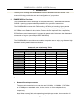
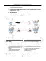
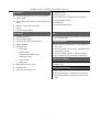
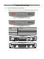
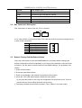

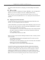
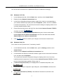
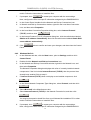


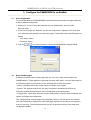
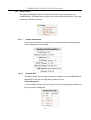

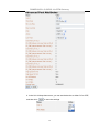

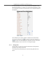
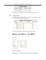


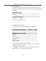
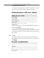

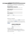
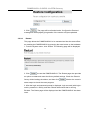

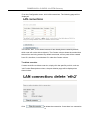
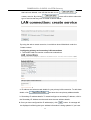
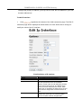


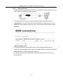
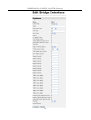
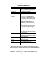

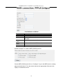

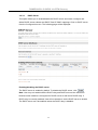


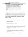


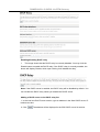


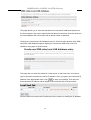


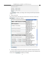
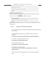
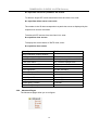
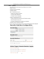
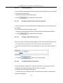

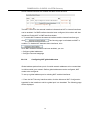


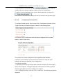
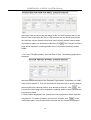


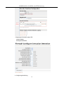
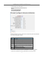

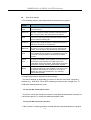
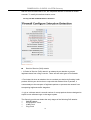

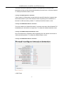

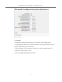
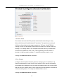

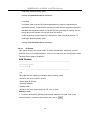


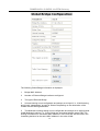
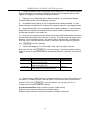
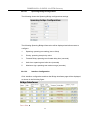

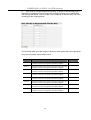

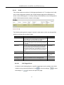
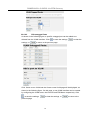

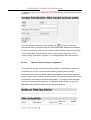


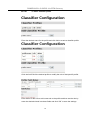


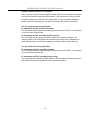


![ABiLINX 2124 取扱説明書[第1.3版]](http://vs1.manualzilla.com/store/data/006689918_2-cb6f92a7c9fd4aba45b2f5ff7183f0a7-150x150.png)