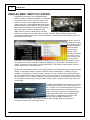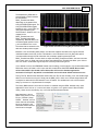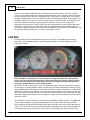
1
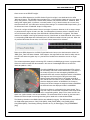
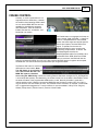
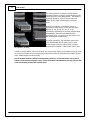
Instruction
Manual
P/N 30-3510
2001–2006 BMW E46 M3
Manual Transmission
Plug & Play Adapter Harness
STOP!
THIS PRODUCT HAS LEGAL RESTRICTIONS.
READ THIS BEFORE INSTALLING/USING!
THIS PRODUCT MAY BE USED SOLELY ON VEHICLES USED IN SANCTIONED COMPETITION WHICH MAY NEVER BE USED UPON A
PUBLIC ROAD OR HIGHWAY, UNLESS PERMITTED BY SPECIFIC REGULATORY EXEMPTION. (VISIT THE “EMISSIONS” PAGE AT HTTP://
WWW.SEMASAN.COM/EMISSIONS FOR STATE BY STATE DETAILS.)
IT IS THE RESPONSIBILITY OF THE INSTALLER AND/OR USER OF THIS PRODUCT TO ENSURE THAT IT IS USED IN COMPLIANCE WITH
ALL APPLICABLE LAWS AND REGULATIONS. IF THIS PRODUCT WAS PURCHASED IN ERROR, DO NOT INSTALL AND/OR USE IT. THE
PURCHASER MUST ARRANGE TO RETURN THE PRODUCT FOR A FULL REFUND.
THIS POLICY ONLY APPLIES TO INSTALLERS AND/OR USERS WHO ARE LOCATED IN THE UNITED STATES; HOWEVER CUSTOMERS
WHO RESIDE IN OTHER COUNTRIES SHOULD ACT IN ACCORDANCE WITH THEIR LOCAL LAWS AND REGULATIONS.
WARNING: This installation is not for the tuning novice! Use this system with EXTREME caution! The AEM
Infinity Programmable EMS allows for total flexibility in engine tuning. Misuse or improper tuning of this
product can destroy your engine! If you are not well versed in engine dynamics and the tuning of engine
management systems DO NOT attempt the installation. Refer the installation to an AEM-trained tuning
shop or call 800-423-0046 for technical assistance.
NOTE: All supplied AEM calibrations, Wizards and other tuning information are offered as potential
starting points only. IT IS THE RESPONSIBILITY OF THE ENGINE TUNER TO ULTIMATELY CONFIRM IF THE
CALIBRATION IS SAFE FOR ITS INTENDED USE. AEM holds no responsibility for any engine damage that
results from the misuse or mistuning of this product!
AEM Performance Electronics
AEM Performance Electronics, 2205 126th Street Unit A, Hawthorne, CA 90250
Phone: (310) 484-2322 Fax: (310) 484-0152
http://www.aemelectronics.com
Instruction Part Number: 10-3510
Document Build 1/7/2015
2
P/N 30-3510
OVERVIEW
The 30-3510 AEM Infinity Adapter Kit was designed for the 2001–2006 BMW E46 M3 with manual
transmission. This is a true standalone system that eliminates the use of the factory BMW DME (ECU).
The use of this adapter makes the kit “plug and play” so no cutting or splicing wires is necessary. The
base configuration files available for the Infinity EMS are starting points only and will need to be modified
for every specific application. Included in these instructions are descriptions of important differences
between using the factory BMW DME and using the AEM Infinity ECU.
The available AEM Infinity EMS part numbers for this adapter kit are:
30-7109 INFINITY-8
30-7105 INFINITY-10
NOTE: The Infinity-10 EMS has 2 extra ignition coil and injector outputs for a total of 10 each. These are
sold separately from this adapter kit.
INFORMATION ON INFINITY ECUS USED ON 2005–06 BMW E46 M3’S EQUIPPED WITH FACTORY
COMPETITION PACKAGE:
When the Infinity is used on 2005–06 model year E46 M3s, the DSC lamp will remain illuminated when
the key is in the “on” position. Certain CAN bus features of the Infinity are not available via the steering
wheel cruise control buttons, as these vehicles did not come with factory cruise control buttons. (The
features integrated through CAN bus can be added using an ancillary trim position switch.)
GETTING STARTED
Refer to the 10-7100 for EMS 30-7100 Infinity Quick Start Guide for additional information on getting
the engine started with the Infinity EMS. E46 BMW M3 base session is located in C:\Documents\AEM
\Infinity Tuner\Sessions\Base Sessions
DOWNLOADABLE FILES
Files can be downloaded from www.aeminfinity.com. An experienced tuner must be available to configure
and manipulate the data before driving can commence. The Quick Start Guide and Full Manual describe
the steps for logging in and registering at www.aeminfinity.com. These documents are available for
download in the Support section of the AEM Electronics website: http://www.aemelectronics.com/
products/support/instructions
Downloadable files for 2001–2006 BMW E46 M3
7105-XXXX-64 Infinity-10 BMW E46
(XXXX = serial number)
7109-XXXX-65 Infinity-8 BMW E46
(XXXX = serial number)
NOTE: The Flash Enable connector (described in the following pages) MUST be “jumped” in
order to connect to the Infinity and load the initial firmware file. Subsequent firmware
upgrades will not require this step.
Ignition key OFF
Insert zip-tied jumper shunt connector into Flash Enable connector
Ignition key ON (RUN position)
Infinity Tuner | Target | Upgrade Firmware… | Upload downloaded .pakgrp file
Disconnect Flash Enable jumper connector
Infinity Tuner | File | Import Calibration Data | Select appropriate base session file
© 2015 AEM Performance Electronics
2001–2006 BMW E46 M3
OPTIONS
30-2001 UEGO Wideband O2 Sensor
Bosch LSU4.2 Wideband O2 Sensor that connects to AEM 30-3600 UEGO Wideband O2 Sensor
Extension Harness
30-3600 UEGO Wideband O2 Sensor Extension Harness
Extension harness to connect AEM UEGO Wideband O2 sensor to 6-pin Deutsch
30-3602 IP67 Logging Cable
USB A-to-A extension cable: 39” long with right angled connector and bayonet style lock
INFINITY CONNECTORS
The AEM Infinity EMS uses the MX123 Sealed Connection
System from Molex. AEM strongly recommends that users
become familiar with the proper tools and procedures for
working with these high density connectors before
attempting any modifications. The entire Molex MX123
User Manual can be downloaded direct from Molex at:
http://www.molex.com/mx_upload/family//
MX123UserManual.pdf
© 2015 AEM Performance Electronics
3
4
P/N 30-3510
INFINITY ADAPTER HARNESS
Included with the BMW E46 M3 kit is an adapter harness. This is used to make the connection between
the AEM Infinity EMS and the BMW wiring harness plug and play. This is depicted below with the 73-pin
and 56-pin connectors and the BMW M3 header. There are also a few other integrated connectors within
this harness described below.
The gray Deutsch 6P DTM “Lambda #1” and “Lambda #2” plugs are for connecting UEGO wideband
Bosch LSU4.2 sensors (AEM 30-2001). The UEGO extension harness (AEM 30-3600) mates the
adapter harness to the sensor (1 required for each sensor used). Note: Even though the BMW S54
engine architecture is inline, the stock exhaust system pairs the cylinders (1,2,3 and 4,5,6) into 2
separate banks. For this case, 2 sensors are recommended. If a single turbocharger is used, 1 sensor is
sufficient.
The gray Deutsch 4P DTM connector is used for “AEMNet”. AEMNet is an open architecture based on
CAN 2.0 which provides the ability for multiple enabled devices, such as dashboards, data loggers, etc.,
to easily communicate with one another through two twisted cables (CAN+/CAN-).
The black Delphi 2-pin “Flash Enable” connector is used for secondary hardware flashing. The included
shunt connector jumps the 2 wires together. Once initially flashed, the EMS is normally upgraded in the
software, not using this connector.
© 2015 AEM Performance Electronics
2001–2006 BMW E46 M3
5
The gray Deutsch 12P DTM “Auxiliary”
connector (shown below) is used to
adapt many common ancillary inputs and
outputs easily. Included in the kit are a
DTM 12P mating connector, 12 DTM
terminals, and a DTM 12P wedgelock. If
used, these components will need to be
terminated by the installer or end user
with 16–22awg wire (not included). Note:
the pin numbering is molded into the
connector, as shown.
Below is a description of each of the
available input/output found in the BMW
specific “Auxiliary” connector.
Available I/O
Typical Use
Fuel Press
This is used for monitoring
fuel pressure input to the
Infinity. It can also be used
to increase or decrease
injector fuel pulse to
compensate for a failing
fuel pump.
Typical electronic fuel
injection fuel pressure
varies 30–100psi.
AEM carries 0–5V
fuel pressure
sensors (sold
separately).
This w ire goes
directly to the signal
w ire of the pressure
sensor.
Air Tem p
Air temperature is typically
used for fuel and ignition
timing correction.
The S54 comes
standard w ith a MAF
sensor w hich has an
integrated intake air
temperature sensor.
This w ire is run in
parallel w ith the stock
sensor. This means if
an aftermarket sensor
is to be w ired using this
pin, the factory MAF
sensor must be
disconnected or else
the signal w ill be
skew ed drastically.
AEM carries air
temperature sensors
(sold separately).
How ever, the Infinity
can accept any
thermistor sensor
and can be
calibrated in the
Infinity Tuner
softw are.
Intake air temp
sensors have tw o
w ires w ith no polarity.
Sensor Ground
Isolated ground for inputs.
This is not the same as
a pow er ground or
chassis ground.
This is shared for
the Fuel Press, Air
Tem p, MAP
(Manifold Press),
Ethanol Sensor,
etc.
This should be w ired
to the ground pin of
the follow ing: Fuel
Press, Air Tem p,
MAP, and Ethanol
Sensor.
5 volt supply for the
follow ing aux inputs.
When measured w ith a
voltmeter, it is normal to
not measure exactly
5V.
This is shared for
the Fuel Press,
MAP (Manifold
Press), and
Ethanol Sensor
inputs.
This should be w ired
to the voltage
reference pin of the
follow ing: Fuel
Press, MAP, and
Ethanol Sensor.
5V Reference
© 2015 AEM Performance Electronics
Notes
Component
Wiring
6
P/N 30-3510
Available I/O
Typical Use
Notes
Component
MAP (Manifold
Press)
Manifold pressure is used
for speed density fuel
calculation, ignition timing
correction, 02 feedback,
boost control, variable
valve control, ancillary
outputs, etc.
Electronic fuel injection
is calculated in absolute
pressure not gauge
pressure.
AEM carries MAP
sensors (sold
separately).
How ever, the Infinity
can accept any 0–
5V pressure sensor
and can be
calibrated in the
Infinity Tuner
softw are.
This should be w ired
directly to the MAP
sensor's signal pin.
Ethanol Sensor
This is used for customers
w ho are converting their
vehicle to utilize ethanol
fuels such as E85 or E98.
This digital input can be
used for other functions
as w ell.
The GM Fuel
Composition Sensor
(FCS) is the most
commonly used for
converting a vehicle
to flex fuel.
This pin needs to be
w ired directly to the
signal pin of the fuel
composition sensor.
Boost Control
Solenoid
This is used to operate a
12V PWM solenoid.
Boost control solenoids
can be normally open
(NO) or normally closed
(NC). This w ill change
the duty cycle strategy
but is also depends
upon how the
w astegate is plumbed
w ith hoses.
AEM carries boost
Solenoids have tw o
control solenoids
w ires and have no
(sold separately).
polarity.
How ever, the Infinity
can control most
factory boost control
solenoids.
Can be used for many
things, how ever, this 12V
source w as implemented
to be paired w ith the
Boost Control Solenoid.
This 12V is coming
through the vehicle's
main relay.
Because of using
shared pow er, this
should only be used
for low current
electronics.
N/A
The Infinity can
directly drive an
electronic
component up to
4amps max, such as
a boost solenoid.
For a relay, this
should be w ired to
terminal 86 (or 85).
Supply chassis
ground to the opposite
terminal 85 (or 86). If
directly driving a low
current component,
w ire this to the 12V
terminal.
Pow er from
Relay
High Side
Output
Boost Target
Trim Selector
Input
Can be used to activate the If attempting to drive a
12V side of a solenoid
component over 4amps,
a relay must be used.
Can be used for to trigger
multiple boost targets.
This analog input can be AEM 12 Position
used for other functions Universal Trim Pot
as w ell.
(or typical
potentiometer). Can
also be used w ith
any simple ON/OFF
sw itch.
Wiring
This w ire should be
routed to the signal
output of the
component. If used
w ith a simple ON/OFF
sw itch, route the
opposite terminal to an
Infinity sensor ground.
© 2015 AEM Performance Electronics
2001–2006 BMW E46 M3
Component
7
Available I/O
Typical Use
Notes
Wiring
Radiator Fan 1
Can be used to operate an
auxiliary fan for a radiator,
intercooler, etc.
This low side (ground)
output can be used for
other functions as w ell.
If attempting to drive a
component over 4amps,
a relay must be used.
The Infinity can
directly drive an
electronic
component up to
4amps max.
For a relay, this
should be w ired to
terminal 85 (or 86).
Supply 12V to the
opposite terminal 86
(or 85). If directly
driving a low current
component, w ire this
to the ground terminal.
No Lift Shift
Trigger
Cutting fuel and/or cutting
spark and/or retarding
ignition timing w hen shifting
gears w ithout releasing the
throttle pedal.
Cut time is typically 200300mS. Ignition retard is
typically 20degree w ith
a 50mS ramp-in time
after the fuel cut.
Ignition cut is not
commonly used.
AEM 12 Position
Universal Trim Pot
(or typical
potentiometer). Can
also be used w ith
any simple ON/OFF
sw itch.
This w ire should be
routed to the signal
output of the
component. If used
w ith a simple ON/OFF
sw itch, route the
opposite terminal to an
Infinity sensor ground.
EXHAUST GAS TEMPERATURE SENSOR
The BMW M3 S54 engine uses an exhaust gas temperature sensor (EGT). This is a 0–5V resistive
temperature device (RTD) that is input to the Infinity EMS. AEM has already done the work by calibrating
and entering the EGT data (shown below) into the base session files. There is currently no fuel control,
but this channel can be data logged for tuning purposes.
© 2015 AEM Performance Electronics
8
P/N 30-3510
DRIVE-BY-WIRE THROTTLE CONTROL
The BMW M3 S54 engine uses 6 individual throttle
bodies controlled via drive-by-wire (DBW). It is important
to note that throttle control is a critical system which
needs to be correct, and the BMW E46 throttle and
intake system is a unique implementation with several
details that require careful attention. The basic terms of
drive-by-wire are as follows: the ‘gas pedal’ inside the
passenger cabin is called the Accelerator Pedal
(DBW_APP1%), while the electronically controlled
throttles in the engine bay are referenced as ‘Throttle’ (Throttle%, DBW1_TPSA%). Based on the
measured Accelerator Pedal position, the ECU determines a desired DBW_Target position and moves
the Throttle to that position.
As shown, there is a
Drive By Wire Wizard
which must be used to
calibrate accelerator
pedal and throttle
position sensors.
Although sensor
calibration values from
one vehicle may be
close enough to work
for another vehicle
under some circumstances, it is absolutely necessary to run the Drive By Wire Wizard before running
the engine for the first time. The wizard should be repeated if any components in the throttle control
system are removed or replaced such as the throttle bodies, TPS sensors, throttle linkage, electronic
throttle control motor, or accelerator pedal.
Please ensure the vehicle’s battery is fully charged (at least 12.5 Volts) before running the Drive By Wire
Wizard, as low battery voltage can result in abnormal sensor measurements. If a battery charger is
available, it is preferable to connect the battery charger in 5A, 10A, or 20A mode and perform the Drive
By Wire Wizard while the battery voltage is near 13.5–14.0 Volts. When connected to the Infinity EMS
with the engine OFF, go to Plug-in | Wizards | Drive By Wire Wizard. On the first page, be sure to check
the ‘Calibrate Sensor Data Only’ checkbox before selecting ‘Start’. Follow the step-by-step instructions
for each page.
The BMW E46 M3 SPORT button located in the center
console (shown) still serves as a switch input to the
ECU. Contrary to some misinformed beliefs, this button
never changed the maximum power output of the
engine. This switch changes the accelerator-pedal to
throttle-target relationship in the stock BMW DME.
These curves are configurable in the Infinity Tuner
software using the DBW_ThrottleCurve1 /
DBW_ThrottleCurve2 tables, which allow the tuner to define the DBW throttle target based on
Accelerator Pedal Position and Engine Speed.
© 2015 AEM Performance Electronics
2001–2006 BMW E46 M3
9
The ModeSelect_DBW table is
preconfigured to switch between
the two different
DBW_ThrottleCurve tables,
depending on the status of the
CAN_SPORTBUTTON signal. The
CAN_SPORTBUTTON toggles
between 0 and 1 (2 and 3 are not
used) when depressing the
SPORT button. States 0 and 1 are
mapped to the
DBW_ThrottleCurve1 and
DBW_ThrottleCurve2 tables
respectively. Both 2D tables use
accelerator pedal position for the
y-axis and RPM for the x-axis.
When accelerator pedal is pressed, idle valve sends m ore airflow into
The values that are entered in the
engine. Airflow increases w hen LS5_Duty is set to low values.
table are throttle position targets.
Between 0-10% accelerator pedal position, the idle valve supplies all airflow to the engine while the
individual throttles remain fully closed. This behavior can be observed in the LS6_Duty table (which
increases airflow through the idle valve when the accelerator pedal is pressed) and the
DBW_ThrottleCurve tables. If tuners desire to adjust the DBW_ThrottleCurve tables, the lower two rows
must remain set to 0. Great care must be taken when adjusting the ThrottleCurve tables, poor choices
here can result in undesirable engine response or drive-by-wire tracking errors.
If it is desired to mimic the OEM BMW throttle control strategy, set the target to 75% throttle below 5500
RPM when the Accel Pedal is 100% open and 90% throttle above 5500 RPM. NOTE: Do not enter
values above 95% in the throttle curve tables; this will force the throttles against the
mechanical ‘full open’ stop which is not desirable and could cause failsafe actions to occur.
Tuning Tool Tip: Because the AEM base session files use TPS as the VE table y-axis, the throttle target
tables can be used as a tuning aid. Simply set the DBW_APP1 100% row to Throttle target values that
correspond to values which need attention in the VE tables. This enables each cell to be accessed
easily by the tuner on a dynamometer for example.
The factory BMW traction control and rev limiter is controlled using the DBW, whereas many other
applications use a fuel cut or, in some rare cases, an ignition cut or ignition retard. With the AEM
Infinity, these can be controlled by any or all of the aforementioned methods.
Note that there is also a
DBW Tuning section in the
Plug-in | Wizards | Setup
Wizard… However, most of
these channels will already
be set up properly in the
AEM base session file and
should not be changed.
© 2015 AEM Performance Electronics
10
P/N 30-3510
There are a few integrated DBW fail safes incorporated into the Infinity system. The ECU constantly
monitors the accelerator pedal sensor voltage and throttle position sensor voltages to ensure the signals
are not excessively high or low due to damaged sensors, short circuits, or broken wires. The ECU also
performs self-diagnostics to ensure the electronic throttle is following desired DBW_Target properly, that
the DBW throttle control motor is not using excessive energy to move the throttle, and watching to see
that all the redundant sensors are working together as expected. If any of these conditions are
determined to be abnormal or unsafe, the ECU can shut the engine down to prevent unintended engine
acceleration. When the ECU shuts the engine off due to problems detected in the DBW system, the
AEM Infinity notifies the driver by illuminating the Engine Malfunction Lamp (EML) on the dashboard. This
error will reset when the ignition key is cycled or if the problem is fixed.
CAN BUS
The AEM Infinity EMS for the BMW E46 M3 supports the majority of the OEM features including:
Tachometer, Oil Temperature Gauge, Coolant Temperature Gauge, A/C Request Button, and Fuel
Consumption (MPG).
When the EMS is connected to a PC and changes are being committed either through table
values or the wizard, the CAN transmission may occasionally pause and the gauges will drop
out one at a time until they all stop working. This does not happen during normal operation.
Cycling the ignition switch will reset everything back.
NOTE: If the vehicle is used on rollers such as a dynamometer where the front wheels and rear wheels
are operating at completely different speeds, the DSC light, the TPMS (tire pressure monitoring system),
and the BRAKE light will illuminate as usual. When the vehicle is driven conservatively on a road, these 3
lights will be OFF like normal. However, if the tires experience any slippage, these 3 lights will flash ON/
OFF, warning the driver of traction issues. If the tires are excessively spun, these 3 lights may stay ON
replicating a dynamometer speed test. If this happens, a simple cycle of the ignition key will reset these
lights back to OFF.
The DSC light is not controlled by the Infinity but by the BMW VDC/ABS controller. The BMW VDC
system, when enabled, may apply brake pressure to one or more of the wheels to maintain
vehicle stability during spirited driving; the DSC light may briefly illuminate or flash during these
events. If excessive wheel slip is encountered then the DSC light may remain illuminated for the
remainder of the current power cycle as the Infinity is not configured to reduce torque during
© 2015 AEM Performance Electronics
2001–2006 BMW E46 M3
11
these events as an OEM ECU might.
Rather than OBD2 diagnostics, the SES-Service Engine Soon light is now dedicated to the AEM
“MILOutput” feature. The AEM MILOutput activates if any 1 of the following inputs are in an error state: air
temp, baro pressure, coolant temp, exhaust back pressure, fuel pressure, UEGO #1, UEGO #2, MAF
analog, MAF digital, MAP, oil pressure, or throttle position. If any of these sensors are not used, they
should be turned OFF in the Wizard to avoid any false readings. To activate the MILOutput feature, go to
the Wizard and check “Enable MIL Output” in Diagnostics.
The red oil can light still illuminates if there is low engine oil pressure. However, it will no longer change
to yellow when the engine oil level is low. But, if an aftermarket oil pressure sensor is installed, the oil
can will illuminate yellow and beep if the AEM failsafe “OilPressProtectOut” is triggered. This feature
needs to be activated in the Engine Protection section of the Wizard, as shown below left. Also, there is
a corresponding RPM dependent “OilPressProtect” 1D Table that needs to be set up as well. When the
oil pressure falls below this set value, the Oil Press Protect feature will be activated.
Rather than OBD2 diagnostics, the EML-Engine Malfunction Lamp on the dash warns the driver if the
“DBW_Error_Fatal” has been activated. If this happens, the engine will be shut down for safety and the
error will reset when the ignition key is cycled and the condition that caused the error is no longer
present.
The coolant temperature gauge’s red warning LED, located in the BMW gauge cluster, is programmable.
When the coolant exceeds the value entered in the channel “CoolantHighLEDLimit” the LED will
illuminate (default = 100C).
The 4000–9000RPM red and yellow tachometer LEDs (shown)
will now always match the current RPM limiter. For example, if
the 2-step rev limiter is active and targeting 5000RPM, the
tachometer LEDs will move the displayed “redline” to 5000RPM.
This happens even if the engine is idling and not actively
banging against the 2-step limiter. If the 2-step rev limiter is
OFF, but the main rev limiter is set to 7000RPM, the LEDs will
show the displayed “redline” at 7000RPM. If the 3-step rev
limiter turns ON and changes the target rev limiter to 6500RPM,
the LEDs will show the displayed “redline” at 6500RPM.
The main rev limiter is configurable in the setup wizard. The 2step and 3-step rev limiters are configurable in the setup wizard
and in corresponding tables. Keep in mind, there are fuel cuts,
spark cuts, ignition retards, and cut start windows. The tachometer LEDs are driven by the lower value
between the fuel and spark cuts and ignores the ignition retard and cut start window RPMs.
The following channels on the BMW CAN bus are available for logging. The AEM traction control utilizes
the CAN wheel speed sensors: CAN_FLWS [MPH], CAN_FRWS [MPH], CAN_RLWS [MPH],
CAN_RRWS [MPH]. The following steering channels are only for data logging: CAN_STEERANGLE
[deg].
© 2015 AEM Performance Electronics
12
P/N 30-3510
The rate of fuel consumption (MPG) is
calculated based on injector duty cycle,
injector size, engine speed, etc. The output
display will be close, but keep in mind there are
many factors and variables. To customize and
make completely accurate, there is a trim
channel named “CAN_FUELFLOWSCALER”.
The default value is 0.000864472.
© 2015 AEM Performance Electronics
2001–2006 BMW E46 M3
13
CRUISE CONTROL
Currently, a cruise control feature is not
supported with the AEM Infinity. However,
the multi-functional steering wheel buttons
are run over the BMW MFL bus and are
available for miscellaneous purposes
described below. There are 4 buttons:
Enable, Resume Set, Accelerate+, and
Decelerate- (as shown).
The Enable button now engages the 3-step rev
limiter channel “CAN_CCEnable”. A 3-step rev
limiter is a simplified traction control based
system that uses engine and vehicle speed or
launch timer inputs to limit the RPM of the
engine. To operate, first be sure the
3StepSwitch table is set to recognize the
“momentary” Enable button, as shown. Set
the 3StepTargetFuel and/or the
3StepTargetSpark table’s first (0 MPH) cell to
the desired launch RPM. When the Enable
button is held down, the EMS will limit the
engine’s corresponding RPM. Once the car is launched and the EMS begins to register vehicle speed,
the RPM limit can then be tailored to prevent wheel spin using these tables.
The Resume Set button is used as an
AEM traction control switch. Note:
The DSC button is not available as
it is a direct link to the VDC. The
BMW VDC system is disabled
when using the AEM Infinity. Instead, the latching Resume Set button changes the TC_SlipTargetTrim
1-axis lookup table (shown). Simultaneously, the Cruise Control icon on the dash is illuminated to inform
the driver the status of the programmable AEM traction control. Normally this table is used with a
multiple position switch. However, because the BMW Resume Set button is either OFF (0) or ON (1),
only the first two cells of the table are used. Two possible traction scenarios, for example, could be ON/
OFF or aggressive/nonaggressive. To use this feature, it must be enabled in Infinity Tuner: Plug-Ins |
Wizard | Setup wizard | Traction Control | Traction Control Enable.
© 2015 AEM Performance Electronics
14
P/N 30-3510
The steering wheel’s Accelerate+ and Deceleratemomentary buttons increment and decrement the map
switching function “CAN_MapValueNV”. This feature is
extremely flexible as it can be used to switch VE
tables, ignition maps, lambda targets, and boost
levels.
When the Accelerate+ or Decelerate- button is
depressed (or when KeyOn occurs) the tachometer
displays 1k, 2K, 3K, 4K, 5K, 6K, 7K, or 8K
momentarily representing the currently selected value
of ModeSwitch. Because of the BMW E46 M3
tachometer range, 1–8 are the only valid values (9–12
are not used for this application).
For safety precautions, the AEM base session files
come standard with the VE tables, ignition maps,
lambda targets, and boost tables all set the same
because the Accelerate+ or Decelerate- button could
be mistakenly bumped.
In order to use this feature, care must be taken into account when setting up the tables and tuning. Enter
the number of the table into the corresponding mode selection table for each feature (VE tables, ignition
maps, lambda targets, and boost levels).
Key Off Commit must be enabled for map position selections, as selected via the cruise control
buttons, to be saved across power cycles. If Key Off Commit is disabled then the map position will
reset to its default position after a power cycle.
© 2015 AEM Performance Electronics
2001–2006 BMW E46 M3
INFINITY EMS INSTALLATION
Step 1
Open the trunk and disconnect the
battery.
Open the hood and locate the E-Box on
the left side near the firewall. This is
where the factory ECU (Digital Motor
Electronics or DME) resides.
Remove the four screws using a T25
Torx wrench (late models) or 5mm Allen
wrench (early models). Simultaneously
pull up and rotate the E-Box cover to
release it from the vehicle. This will be
reused.
Step 2
There are 5 DME connectors. These
must be removed in a sequence from the
left to the right (as pictured) or connector
5-4-3-2-1.
First remove connector 5 using your
thumb by squeezing the release tab.
Hold down and pull upwards.
© 2015 AEM Performance Electronics
15
P/N 30-3510
16
Step 3
Connectors 4, 3 and 2 all have a
swinging latch. First press the “button”
and then rotate the swing latch
downwards towards the DME.
Note: When reinserting connectors into
the header, the swing latch must be
open for initial engagement.
Step 4
The connector will automatically push
itself away from the DME connector’s
header.
After removing connectors 4, 3, and 2,
remove connector 1 the same way as
connector 5 using your thumb.
© 2015 AEM Performance Electronics
2001–2006 BMW E46 M3
Step 5
To remove the DME (stock ECU) from
the internal plastic “skeleton”, push the
two tabs away from the bottom side of
the DME, as shown.
Step 6
Simultaneously unlock the plastic tabs
and pull the DME up and out of the
engine bay.
The stock DME will NOT be reused.
© 2015 AEM Performance Electronics
17
P/N 30-3510
18
Step 7
Next, there will need to be room made
for the AEM Infinity EMS and jumper
box to fit within the E-Box
compartment.
Note: Some of the instructions below
may slightly differ from vehicle to
vehicle.
Unplug the 2 white connectors (shown)
by squeezing each connector’s locking
tabs.
Note: These two connections will be
reconnected later.
Step 8
Using a flat blade, such as a
screwdriver, unlock the black fuse
block’s tab, as shown, and lift upwards.
© 2015 AEM Performance Electronics
2001–2006 BMW E46 M3
Step 9
Using a flat blade, such as a
screwdriver, unlock the blue relay’s tab,
as shown, and lift upwards.
Step 10
Using a flat blade, such as a
screwdriver, unlock the lime green
relay’s tab, as shown, and lift upwards.
© 2015 AEM Performance Electronics
19
20
P/N 30-3510
Step 11
Carefully pull the internal plastic mount
upwards a few inches to unlock it from
the base.
Step 12
Cut the factory cable zip-ties to release
the BMW wiring harness from the
internal plastic mount using a pair of
long-reach dikes.
Cut the zip-tie shown.
© 2015 AEM Performance Electronics
2001–2006 BMW E46 M3
Step 13
There should be 2 cable ties to cut in
the area shown.
Step 14
Pull the internal plastic mount further
away from the vehicle and cut the zip-tie
shown.
© 2015 AEM Performance Electronics
21
22
P/N 30-3510
Step 15
As shown, use a pick to unlock this tab.
Pull the connector downwards to release
it from the inner plastic “skeleton”.
Step 16
The internal plastic “skeleton” should
now be able to be removed.
To allow space for the AEM EMS kit,
the top portion (that the DME was
secured to) will have to be cut into 2
pieces.
Using a band saw (or similar) cut the
“skeleton” along the dotted line as
pictured.
© 2015 AEM Performance Electronics
2001–2006 BMW E46 M3
Step 17
The pictured piece can be discarded.
Reinstall the other part of the plastic
“skeleton”. Reconnect the relays and
white plastic connector from the previous
steps.
Connect the AEM jumper box and the
90-degree locking comms cable to the
AEM Infinity EMS.
Insert the Infinity in a vertical position
where the DME was mounted previously.
The 2 large Infinity connector cables
should be facing upwards. Note: Infinity
blue connector towards front and gray
connector towards rear of vehicle.
Step 18
Connect the AEM jumper box to the 5
factory BMW DME connectors in
reverse order (1-2-3-4-5). Place the
jumper box on top of the AEM Infinity
EMS, as shown.
Connect the UEGO extension
harness(s) to the “Lambda1” (and/or
“Lambda2”) 6-pin DTM connector(s). If
using any AEMNet components, such
as an AEM AQ-1 Datalogger, use the 4pin Deutsch DTM “AEMNET” connector.
Evaluate which ancillary sensors, inputs,
and/or outputs will be required to run the
vehicle. Using the aux pin-out
information, wire the components into
the included 12P connector. Plug this
into the adapter harness connector
labeled “AUX”.
© 2015 AEM Performance Electronics
23
24
P/N 30-3510
Step 19
Before reinstalling the E-Box cover, cut
half-circle slot(s) along the edge, shown
in yellow. This will allow the comms and
miscellaneous cables to exit the E-Box.
This kit requires a MAP sensor. Use the
aux connector pinout to wire in a sensor
and route the wires through the E-Box
cover.
Using a 7/8” wrench, install the optional
AEM UEGO sensor(s) in the exhaust at
least 36” from the turbo (if applicable).
Connect the UEGO extension
harness(s) to the sensor(s).
Position everything being cautious not to
pinch any of the cables. Secure the EBox cover with the factory fasteners.
This will be a very tight fit.
Step 20
To remove the cowl, disengage the 3
quarter-turn fasteners and remove the
interior ventilation filter cover and micro
filter element.
Unclip the 4 tabs for the cable duct in
front of the cowl and separate the two
long pieces. Make sure the engine is
cool and pull the large cables out of the
plastic retaining seats and gently lay
them down on the engine.
Unscrew the four T30 Torx bolts and
remove the lower section of the micro
filter housing by pulling towards the front
of the vehicle.
© 2015 AEM Performance Electronics
2001–2006 BMW E46 M3
Step 21
Towards the back of the vacuum rail
there is a barbed nipple (shown). There
is a short 90-degree rubber hose (not
shown) and corresponding hard plastic
tube (shown) that connects the vacuum
rail to the fuel pressure regulator under
the vehicle.
Pull the short rubber hose off the
vacuum rail. Be careful not to lose the
hard plastic tube which will be zip-tied in
place by BMW.
Step 22
Using the barbed TEE and rubber
vacuum hose included with the kit,
install the MAP sensor’s vacuum
source, as shown.
Find a location to remotely mount the
MAP sensor. Be sure to keep the
vacuum hose and electrical cables away
from hot exhaust gas areas or moving
parts.
Connect the MAP sensor to the auxiliary
connector.
The electrical and mechanical
installation of the BMW E46 M3 Infinity
EMS PnP kit is now complete.
© 2015 AEM Performance Electronics
25
P/N 30-3510
26
PINOUTS
BMW Pinouts
BMW
Pin
X
6
0
0
0
1
X
6
0
0
0
2
Dedicated
Dedicated and not reconfigurable
Assigned
Assigned but reconfigurable
Available
Available for user setup
Not Applicable
Not used in this configuration
Required
Required for proper function
01–06 E46 M3
00–02 M Coupe
00–02 M
Roadster
EMS
Pin
Hardw are
Reference
Function
Hardw are
Specification
Notes
12 volt power from relay
12 volt power from relay. Relay must be
controlled by +12V Relay Control signal
pin C1-29.
5.0A max Throttle Control Hbridge
Drive
+12V to open
PGND
Power Ground
Connect directly to battery ground.
GND
PGND
Power Ground
Connect directly to battery ground.
GND
PGND
Power Ground
Connect directly to battery ground.
C1-10
+12V_R8C_CPU
+12V (Perm
Power)
Dedicated power management CPU
Full time battery power. MUST be
powered before the ignition switch input
is triggered.
Voltage Supply-Engine
Electronics Fuse Carrier
C1-61
+12V
+12V
12 volt power from relay
Relay must be controlled by +12V Relay
Control signal pin C1-29.
9
Negative Activation-EDK
Actuator with
Potentiometer
C1-53
Harness_HBridge0_0
HBridge0_0
5.0A max Throttle Control Hbridge
Drive
+12V to close
1
Heater Ground-Oxygen
Sensor I Before Catalytic
Converter
NC
2
Not Used
NC
3
Not Used
NC
4
Not Used
NC
5
Negative ActivationOxygen Sensor Grounds
NC
6
Not Used
NC
7
Heater Ground-Oxygen
Sensor I Behind Catalytic
Converter
NC
8
Not Used
NC
9
Not Used
NC
10
Signal-Exhaust
Temperature Sensor
C2-17
Harness_Analog_In_T
emp_6
Exhaust Temp
12 bit A/D, 2.49K pullup to 5V
See ExhTemp [C] table for calibration
data and ExhTemp [C] for channel data.
11
Signal-Fuel Pump Relay
C1-34
Harness_LowsideSwit
Fuel Pump
Lowside switch, 4A max, NO internal
Switched ground. Will prime for 2
1
Fuel Injector RelayTerminal 15
C1-61
+12V
+12V
2
Voltage Supply-EDK
Actuator with
Potentiometer
C1-54
Harness_HBridge0_1
HBridge0_1
3
Diagnosis Signal TXD
SMG2 Control Module
(SMG Only)
4
Ground Point
C1-30
GND
5
Ground Connector
C1-55
6
Ground Connector
C1-60
7
Fuse F102-Terminal 30
8
NC
© 2015 AEM Performance Electronics
2001–2006 BMW E46 M3
BMW
Pin
01–06 E46 M3
00–02 M Coupe
00–02 M
Roadster
EMS
Pin
1 (USA Models Only)
X
6
0
0
0
3
Function
ch_0
12
Signal-E-Box Fan
Temperature
13
Heater Ground-Oxygen
Sensor II Before Catalytic
Converter
NC
14
Signal-Heated Oxygen
Sensor I Before Catalytic
Converter
NC
15
Signal-Heated Oxygen
Sensor II Before Catalytic
Converter
NC
16
Signal-Heated Oxygen
Sensor I Behind Catalytic
Converter
NC
17
Not Used
NC
18
Signal-Heated Oxygen
Sensor II Behind Catalytic
Converter
NC
19
Heater Ground-Oxygen
Sensor II Behind Catalytic
Converter
NC
20
Signal-Gear Recognition
Clutch Switch
C2-38
21
Signal-CAN Bus Low
SMG2 Control Module
(SMG Only)
NC
22
Signal-CAN Bus High
SMG2 Control Module
(SMG Only)
NC
23
Signal-Main Relay
Activation-DME Relay
C1-29
24
Not Used
1
Signal-Hot-Film Mass
Air Flow Sensor
2
Signal-Exhaust Camshaft
Position Sensor I
3
Not Used
4
Activation VANOS Inlet
Valve Advance
5
Signal-Inlet Camshaft
Position Sensor I
6
Signal-Exhaust Camshaft
Position Sensor II
NC
7
Voltage Supply-Hot-Film
Mass Air Flow Sensor
EDK Actuator
8
Signal-Crankshaft
Position Sensor
9
Not Used
10
Signal-EDK Actuator with
© 2015 AEM Performance Electronics
Hardw are
Reference
Hardw are
Specification
27
Notes
flyback diode.
seconds at key on and activate if RPM >
0.
GND
Harness_Digital_In_7
Clutch Switch
10K pullup to 12V. Will work with
ground or floating switches.
See ClutchSwitch 1-axis table for setup
options. Open unless clutch out and
gear in = 12V
Harness_
+12V_Relay_Control
Main Relay
0.7A max ground sink for external
relay control
Will activate at key on and at key off
according to the configuration settings.
12 bit A/D, 100K pullup to 5V
0–5V analog signal. Use +5V Out pins
as power supply and Sensor Ground
pins as the low reference. Do not
connect signals referenced to +12V as
this can permanently damage the ECU.
10K pullup to 12V. Will work with
ground or floating switches.
See Setup Wizard page Cam/Crank for
options.
Lowside switch, 4A max with internal
flyback diode. Inductive load should
NOT have full time power.
BMW VANOS Control
NC
C2-33
Harness_Analog_In_2
0
MAF Analog
C1-22
Harness_Digital_In_1
Cam1
C2-44
Harness_LowsideSwit
ch_7
VANOS
C1-23
Harness_Digital_In_2
Cam2
10K pullup to 12V. Will work with
ground or floating switches.
See Setup Wizard page Cam/Crank for
options.
C2-24
+5V_OUT_2
Sensor +5V
Regulated, fused +5V supply for
sensor power
Analog sensor power
C1-45
Harness_VR+_In_0
Crank +
Differential Variable Reluctance
Zero Cross Detection
See Setup Wizard page Cam/Crank for
options.
Harness_Analog_In_1
Throttle2
12 bit A/D, 100K pullup to 5V
0–5V analog signal. Use +5V Out pins
NC
NC
C2-21
28
P/N 30-3510
BMW
Pin
01–06 E46 M3
00–02 M Coupe
00–02 M
Roadster
EMS
Pin
Potentiometer
Hardw are
Reference
Function
Hardw are
Specification
as power supply and Sensor Ground
pins as the low reference. Do not
connect signals referenced to +12V as
this can permanently damage the ECU.
6
11
Not Used
NC
12
Not Used
NC
13
Signal-Generator
Terminal 61
N/A
14
Voltage Supply-Throttle
Position Sensor
15
Not Used
NC
16
Not Used
NC
17
Ground-Hot-Film Mass
Air Flow Sensor
18
Not Used
NC
19
Tire Pressure Warning
Pushbutton
NC
20
Ground-EDK Actuator
with Throttle Position
Sensor
21
22
Notes
Regulated, fused +5V supply for
sensor power
Analog sensor power
Sensor Ground
Dedicated analog ground
Analog 0–5V sensor ground
AGND_2
Sensor Ground
Dedicated analog ground
Analog 0–5V sensor ground
C1-46
Harness_VR-_In_0
Crank -
Differential Variable Reluctance
Zero Cross Detection
See Setup Wizard page Cam/Crank for
options.
C1-67
Harness_Analog_In_T
emp_2
Intake Air Temp
12 bit A/D, 2.49K pullup to 5V
See "Air Temperature" Setup Wizard for
selection.
C1-42
+5V_OUT_1
Sensor +5V
AGND_2
C2-32
Ground-Crankshaft
Position Sensor
Signal-Intake Air
Temperature
C2-32
23
Signal-Throttle Position
Sensor
C1-35
Harness_Analog_In_7
Throttle Position
12 bit A/D, 100K pullup to 5V
0–5V analog signal. Use +5V Out pins
as power supply and Sensor Ground
pins as the low reference. Do not
connect signals referenced to +12V as
this can permanently damage the ECU.
See the Setup Wizard Set Throttle
Range page for automatic min/max
calibration. Monitor the Throttle [%]
channel. Also DB1_TPSA [%] for DBW
applications.
24
Signal-Engine Coolant
Temperature Sensor
C1-66
Harness_Analog_In_T
emp_1
Coolant Temp
12 bit A/D, 2.49K pullup to 5V
See "Coolant Temperature" Setup
Wizard for selection.
25
Ground-Engine Coolant
Temperature and Knock
Sensors
C1-19
AGND_1
Sensor Ground
Dedicated analog ground
Analog 0-5V sensor ground
26
Signal-Oil Pressure
Switch
N/A
27
Not Used
NC
28
Not Used
NC
29
Signal-Knock Sensor (Cyl
1-2)
C1-27
Knock1
Knock1
Dedicated knock signal processor
See Setup Wizard page Knock Setup for
options.
30
Signal-Knock Sensor (Cyl
3-4)
NC
31
Signal-Knock Sensor (Cyl
5-6)
C1-28
Knock2
Knock2
Dedicated knock signal processor
See Setup Wizard page Knock Setup for
options.
32
Not Used
33
Signal-Cylinder 1 Fuel
Injection Valve
C1-63
Injector 1
Injector 1
Saturated or peak and hold, 3A max
continuous
Injector 1
34
Signal-Cylinder 2 Fuel
Injection Valve
C1-62
Injector 2
Injector 2
Saturated or peak and hold, 3A max
continuous
Injector 2
35
Signal-Cylinder 3 Fuel
Injection Valve
C1-59
Injector 3
Injector 3
Saturated or peak and hold, 3A max
continuous
Injector 3
36
Signal-Cylinder 4 Fuel
C1-58
Injector 4
Injector 4
Saturated or peak and hold, 3A max
Injector 4
NC
© 2015 AEM Performance Electronics
2001–2006 BMW E46 M3
BMW
Pin
01–06 E46 M3
00–02 M Coupe
00–02 M
Roadster
EMS
Pin
Hardw are
Reference
Function
Injection Valve
X
6
0
0
0
4
Hardw are
Specification
29
Notes
continuous
37
Signal-Cylinder 5 Fuel
Injection Valve
C1-57
Injector 5
Injector 5
Saturated or peak and hold, 3A max
continuous
Injector 5
38
Signal-Cylinder 6 Fuel
Injection Valve
C1-56
Injector 6
Injector 6
Saturated or peak and hold, 3A max
continuous
Injector 6
39
Signal-Oil Level Sensor
C1-24
Harness_Digital_In_3
Digital 3
10K pullup to 12V. Will work with
ground or floating switches.
Used for BMW Oil Temperature Gauge
40
Not Used
NC
41
Not Used
NC
42
Signal-Evaporative
Emission Valve
C1-18
Harness_LowsideSwit
ch_3
LS3
Lowside switch, 4A max, NO internal
flyback diode.
Lowside switch, 4A max with internal
flyback diode. Inductive load should NOT
have full time power.
43
Signal-VANOS Exhaust
Valve Retard
C1-02
Harness_LowsideSwit
ch_5
VANOS
Lowside switch, 4A max with internal
flyback diode. Inductive load should
NOT have full time power.
BMW VANOS Control
44
Signal-VANOS Exhaust
Valve Advance
C1-02
Harness_LowsideSwit
ch_5
VANOS
Lowside switch, 4A max with internal
flyback diode. Inductive load should
NOT have full time power.
BMW VANOS Control
45
Tire Pressure Warning
Lamp (Except M3)
NC
46
Signal-Close Idle Speed
Control Valve
C1-03
Harness_LowsideSwit
ch_6
Idle Air Control
Lowside switch, 4A max with internal
flyback diode. Inductive load should
NOT have full time power.
BMW Idle Air Control
47
Signal-Open Idle Speed
Control Valve
C1-03
Harness_LowsideSwit
ch_6
Idle Air Control
Lowside switch, 4A max with internal
flyback diode. Inductive load should
NOT have full time power.
BMW Idle Air Control
48
Not Used
NC
49
Not Used
NC
50
Signal-VANOS Inlet
Valve Retard
Harness_LowsideSwit
ch_7
VANOS
Lowside switch, 4A max with internal
flyback diode. Inductive load should
NOT have full time power.
BMW VANOS Control
51
Signal-Sucking Jet Pump
Valve
NC
52
Crankcase Breather Valve
(2005-2006 Models)
NC
1
Signal-Battery Charge
Indicator
N/A
2
Signal-Engine Start
Feedback (M3 Only)
NC
3
Signal-Secondary Air
Injection Pump Relay
NC
4
Signal-Electric Fan
C2-43
Harness_LowsideSwit
ch_8
A/C Fan
Lowside switch, 4A max with internal
flyback diode and 12V pullup
resistor. Inductive load should NOT
have full time power.
Lowside switch, 4A max with internal
flyback diode and 12V pullup resistor.
Inductive load should NOT have full time
power.
5
Ground Point (M3 Only)
C2-03
GND
PGND
Power Ground
Connect directly to battery ground.
6
Signal-Ignition Lock
Control Module for
Instrument Cluster
Terminal 50
7
Ground-Pedal-Position
Sensor
C1-20
AGND_1
Sensor Ground
Dedicated analog ground
Analog 0–5V sensor ground
8
Signal-Pedal-Position
Sensor
C2-13
Harness_Analog_In_1
8
APP1
12 bit A/D, 100K pullup to 5V
12 bit A/D, 100K pullup to 5V
9
Voltage Supply-Pedal-
C2-22
+5V_OUT_2
Sensor +5V
Regulated, fused +5V supply for
Analog sensor power
© 2015 AEM Performance Electronics
C2-44
NC
30
P/N 30-3510
BMW
Pin
01–06 E46 M3
00–02 M Coupe
00–02 M
Roadster
EMS
Pin
Hardw are
Reference
Function
Position Sensor
10
Signal Fuel Pump Relay 1
(Not USA Models)
11
Signal-Oil Pressure
Control Module for
Instrument Cluster
12
Ground-Pedal-Position
Sensor
Hardw are
Specification
Notes
sensor power
Harness_LowsideSwit
ch_0
Fuel Pump
C2-30
AGND_2
Sensor Ground
13
Signal-Pedal-Position
Sensor
C2-14
Harness_Analog_In_1
9
APP2
14
Voltage Supply-PedalPosition Sensor
C2-23
+5V_OUT_2
15
Signal-Driving Dynamics
Switching Center (M3
Only)
N/A
16
Driving Dynamics Active
LED-Switching Center
(M3 Only)
N/A
17
Engine Speed Signal TDData Link Connector
NC
18
Activation HeatingDiagnostic Fuel Tank
Leakage (USA M3 Only)
NC
19
Reversing Light Switch
(M Roadster Only)
NC
20
Fuel Leakage Valve (Sept
01-up USA M3)/Thermal
Oil Level Switch (M
Roadster)
NC
21
Signal-Oil Level Control
Module for Instrument
Cluster (Except M
Roadster)
C1-24
22
Signal-Processed Wheel
Speed Rear Right-ABS/
ASC Unit ABS/DSC Unit
C1-25
23
Not Used
24
Signal-Brake Light
Switching Center Control
Unit
25
Not Used
26
Fuse F29-Terminal 15
27
Volute Spring-Data Link
MFL
N/A
28
Signal-Fuel Leakage
Pump Module (Sept 01
and Earlier Models Only)
NC
29
Signal-Relay A/C
Compressor
C1-01
30
Signal-Leakage
Diagnosis Pump
NC
31
Not Used
NC
32
Signal-Data Link TXD-
NC
C1-34
Lowside switch, 4A max, NO internal
flyback diode.
Lowside switch, 4A max, NO internal
flyback diode.
Dedicated analog ground
Analog 0–5V sensor ground
12 bit A/D, 100K pullup to 5V
0–5V analog signal. Use +5V Out pins
as power supply and Sensor Ground
pins as the low reference. Do not
connect signals referenced to +12V as
this can permanently damage the ECU.
Sensor +5V
Regulated, fused +5V supply for
sensor power
Analog sensor power
Harness_Digital_In_3
Digital 3
10K pullup to 12V. Will work with
ground or floating switches.
Used for BMW Oil Temperature Gauge
Harness_Digital_In_4
VSS (Hz)
10K pullup to 12V. Will work with
ground or floating switches.
See Setup Wizard page Vehicle Speed
for calibration constant.
Harness_Digital_In_6
Brake Switch
10K pullup to 12V. Will work with
ground or floating switches.
Input can be assigned to different pins.
See Setup Wizard page Input Function
Assignments for input mapping options.
Harness_+12V_SW
IGN Switch
10K pulldown
Full time battery power must be available
at C1-10 before this input is triggered.
Harness_LowsideSwit
ch_4
AC Compressor
Lowside switch, 4A max, NO internal
flyback diode.
See Setup Wizard Pages "User GPOs"
for activation criteria and "LowSide
Assignment Tables" for output
assignment
N/A
NC
C2-37
NC
C1-65
© 2015 AEM Performance Electronics
2001–2006 BMW E46 M3
BMW
Pin
01–06 E46 M3
00–02 M Coupe
00–02 M
Roadster
EMS
Pin
Hardw are
Reference
Function
Hardw are
Specification
31
Notes
Data Link Connector
X
6
0
0
0
5
33
Electronic Vehicle
Immobilizer Control Unit
NC
34
Signal-Brake Light Switch
NC
35
Cruise Control Ground
(Except M3)
NC
36
Signal-Connector CAN
Bus High
C2-41
Harness_CanH_Bout
CAN B +
Dedicated High Speed CAN
Transceiver
BMW CAN bus communication
37
Signal-Connector CAN
Bus Low
C2-42
Harness_CanL_Bout
CAN B -
Dedicated High Speed CAN
Transceiver
BMW CAN bus communication
38
Ground-Coolant Outlet
Temperature Sensor (M3
Only)
C2-31
AGND_2
Sensor Ground
Dedicated analog ground
Analog 0–5V sensor ground
39
Signal-Coolant Outlet
Temperature Sensor (M3
Only)
C2-15
Harness_Analog_In_T
emp_4
ChargeOutTemp
12 bit A/D, 2.49K pullup to 5V
See ChargeOutTemp [C] table for
calibration data and ChargeOutTemp
[C] for channel data.
40
Not Used
1
Signal-Ignition Coil 1
C1-14
Ignition 1
Ignition 1
25 mA max source current
0–5V Falling edge fire. DO NOT
connect directly to coil primary. Must
use an ignitor OR CDI that accepts a
FALLING edge fire signal.
2
Signal-Ignition Coil 2
C1-13
Ignition 2
Ignition 2
25 mA max source current
0–5V Falling edge fire. DO NOT
connect directly to coil primary. Must
use an ignitor OR CDI that accepts a
FALLING edge fire signal.
3
Signal-Ignition Coil 3
C1-12
Ignition 3
Ignition 3
25 mA max source current
0–5V Falling edge fire. DO NOT
connect directly to coil primary. Must
use an ignitor OR CDI that accepts a
FALLING edge fire signal.
4
Not Used
5
Ground Connector
C1-73
GND
PGND
Power Ground
Connect directly to battery ground.
6
Signal-Ignition Coil 5
C1-16
Ignition 5
Ignition 5
25 mA max source current
0–5V Falling edge fire. DO NOT
connect directly to coil primary. Must
use an ignitor OR CDI that accepts a
FALLING edge fire signal.
7
Signal-Ignition Coil 6
C1-15
Ignition 6
Ignition 6
25 mA max source current
0–5V Falling edge fire. DO NOT
connect directly to coil primary. Must
use an ignitor OR CDI that accepts a
FALLING edge fire signal.
8
Not Used
9
Signal-Ignition Coil 4
Ignition 4
Ignition 4
25 mA max source current
0–5V Falling edge fire. DO NOT
connect directly to coil primary. Must
use an ignitor OR CDI that accepts a
FALLING edge fire signal.
© 2015 AEM Performance Electronics
NC
NC
NC
C1-11
32
P/N 30-3510
Infinity Pinouts
Dedicated
Dedicated and not reconfigurable
Assigned
Assigned but reconfigurable
Available
Available for user setup
Not Applicable
Not used in this configuration
Required
Required for proper function
Infinity
Pin
Hardware
Reference
AEM / M3
Function
BMW M3
Pin
Hardware Specification
Notes
C1-1
LowsideSwitch_4
A/C
Compressor
Clutch Relay
4-29
Lowside switch, 4A max,
NO internal f ly back diode.
See Setup Wizard Page "LowSide Assignment
Tables" f or output assignment, Honda VTEC
f or VANOS triggering and 2D table "LS3_Duty
[%]" f or on/of f activ ation.
C1-2
LowsideSwitch_5
VanosExhaust Cam
3-43, 3-44
Lowside switch, 4A max
with internal f ly back diode.
Inductiv e load should NOT
hav e f ull time power.
The Vanos driv ers are located in the AEM
Jumper Box. BMW Vanos cannot be wired
directly to the Inf inity .
C1-3
LowsideSwitch_6
Idle Air
Control
3-46, 3-47
Lowside switch, 4A max
with internal f ly back diode.
Inductiv e load should NOT
hav e f ull time power.
The S54 engine uses both an IACV and driv e
by wire throttles. Idle speed and low APP
request is controlled using the IACV.
Lowside switch f or UEGO heater control.
Connect to pin 4 of Bosch UEGO sensor.
NOTE that pin 3 of the Sensor is heater (+)
and must be power by a f used/switched 12V
supply .
C1-4
UEGO 1 Heat
UEGO 1 Heat
C1-5
UEGO 1 IA
UEGO 1 IA
C1-6
UEGO 1 IP
UEGO 1 IP
C1-7
UEGO 1 UN
UEGO 1 UN
Nernst Voltage signal. Connect to pin 1 of
Bosch UEGO sensor.
C1-8
UEGO 1 VM
UEGO 1 VM
Virtual Ground signal. Connect to pin 5 of
Bosch UEGO sensor.
10K pulldown
Not usually needed f or automatic f irmware
updates through Inf inity Tuner. If connection
errors occur during update, jump the 12V
Flash Connector bef ore proceeding with
upgrade. Disconnect the 12V Flash Connector
af ter the update.
Use 30-3600
Inf inity O2
Sensor
Extension
Harness
Bosch UEGO controller
Trim Current signal. Connect to pin 2 of Bosch
UEGO sensor.
Pumping Current signal. Connect to pin 6 of
Bosch UEGO sensor.
C1-9
Flash_Enable
Flash Enable
C1-10
+12V_R8C_CPU
Battery Perm
12V Power
1-7
Dedicated power
management CPU
Full time battery power. MUST be powered
bef ore the ignition switch input is triggered.
(See C1-65.)
C1-11
Coil 4
Coil 4
5-9
25 mA max source current
The ignitors are f ound in the AEM Jumper Box.
The BMW Coils cannot be wired directly to the
Inf inity .
C1-12
Coil 3
Coil 3
5-3
25 mA max source current
The ignitors are f ound in the AEM Jumper Box.
The BMW Coils cannot be wired directly to the
Inf inity .
C1-13
Coil 2
Coil 2
5-2
25 mA max source current
The ignitors are f ound in the AEM Jumper Box.
The BMW Coils cannot be wired directly to the
Inf inity .
© 2015 AEM Performance Electronics
2001–2006 BMW E46 M3
Infinity
Pin
Hardware
Reference
AEM / M3
Function
BMW M3
Pin
Hardware Specification
Notes
33
C1-14
Coil 1
Coil 1
5-1
25 mA max source current
The ignitors are f ound in the AEM Jumper Box.
The BMW Coils cannot be wired directly to the
Inf inity .
C1-15
Coil 6
Coil 6
5-7
25 mA max source current
The ignitors are f ound in the AEM Jumper Box.
The BMW Coils cannot be wired directly to the
Inf inity .
C1-16
Coil 5
Coil 5
5-6
25 mA max source current
The ignitors are f ound in the AEM Jumper Box.
The BMW Coils cannot be wired directly to the
Inf inity .
C1-17
LowsideSwitch_2
Lowside switch, 4A max,
NO internal f ly back diode.
Found on Aux Connector. See Wizard page
"LowSide Assignment Tables" f or output
assignment and 2D table "LS2_Duty [%]" f or
activ ation.
LS2
Ev ap
Emission
Valv e
3-42
Lowside switch, 4A max
with internal f ly back diode.
Inductiv e load should NOT
hav e f ull time power.
See Wizard page "LowSide Assignment Tables"
f or output assignment and 2D table
"LS3_Duty [%]" f or activ ation. MIL Activ ates
when any of the f ollowing f lags are true:
ErrorAirTemp, ErrorBaro, ErrorCoolantTemp,
ErrorEBP, ErrorFuelPressure,
UEGO_0_Diag_error, UEGO_1_Diag_error,
ErrorMAFAnalog, ErrorMAFDigital, ErrorMAP,
ErrorOilPressure, ErrorThrottle.
AGND_1
Coolant and
Knock Ground
3-25
Dedicated analog ground
Analog 0–5V sensor ground
C1-20
AGND_1
Pedal Sensor
Ground
4-7
Dedicated analog ground
Analog 0–5V sensor ground
C1-21
Crank Position
Sensor Hall
Crank
Position
Sensor Hall
10K pullup to 12V. Will
work with ground or
f loating switches.
The BMW S54 uses a VR Crank Sensor, not a
Hall Ef f ect Crank Sensor. See Setup Wizard
page Cam/Crank f or options.
C1-22
Cam Position
Sensor 1 Hall
Exhaust Cam
Sensor 1
3-2
10K pullup to 12V. Will
work with ground or
f loating switches.
See Setup Wizard page Cam/Crank f or
options.
C1-23
Digital_In_2
Camshaf t
Position
Sensor 2 Hall
3-5
10K pullup to 12V. Will
work with ground or
f loating switches.
See Setup Wizard page Cam/Crank f or
options.
C1-24
Digital_In_3
Oil Lev el
Sensor
3-39
10K pullup to 12V. Will
work with ground or
f loating switches.
Input used to driv e the Oil Temperature Gauge
on dash v ia CAN bus.
C1-25
Digital_In_4
Vehicle Speed
Sensor
4-22
10K pullup to 12V. Will
work with ground or
f loating switches.
See Setup Wizard page Vehicle Speed f or
calibration constant.
C1-26
Digital_In_5
Flex Fuel
10K pullup to 12V. Will
work with ground or
f loating switches.
Found on Aux Connector. See channel
FlexDigitalIn [Hz] f or raw f requency input
data.
C1-27
Knock Sensor 1
Knock Sensor
1
3-29
Dedicated knock signal
processor
See Setup Wizard page Knock Setup f or
options.
C1-28
Knock Sensor 2
Knock Sensor
2
3-31
Dedicated knock signal
processor
See Setup Wizard page Knock Setup f or
options.
C1-29
+12V_Relay _
Control
Main Relay
2-23
0.7A max ground sink f or
external relay control
Will activ ate at key on and at key of f
according to the conf iguration settings.
C1-30
Power Ground
Ground
1-4
Power Ground
Connect directly to ground.
C1-31
CANL_Aout
AEMNet
CANL
Dedicated High Speed
CAN Transceiv er
4P DTM Connector f ound in AEM adapter
harness. Contact AEM f or additional
inf ormation.
C1-18
LowsideSwitch_3
C1-19
© 2015 AEM Performance Electronics
34
P/N 30-3510
Infinity
Pin
C1-32
Hardware
Reference
CANH_Aout
AEM / M3
Function
BMW M3
Pin
AEMNet
CANH
Hardware Specification
Notes
Dedicated High Speed
CAN Transceiv er
4P DTM Connector f ound in AEM adapter
harness. Contact AEM f or additional
inf ormation.
Lowside switch, 4A max
with internal f ly back diode.
Inductiv e load should NOT
hav e f ull time power.
Found in Aux Connector. See Setup Wizard
page Boost Control f or options. Monitor
BoostControl [%] channel f or output state.
C1-33
LowsideSwitch_1
Boost Control
C1-34
LowsideSwitch_0
Fuel Pump
2-11, 4-10
Lowside switch, 4A max,
NO internal f ly back diode.
Pin is located in 2 dif f erent locations
depending on E46 M3. Switched ground. Will
prime f or 2 seconds at key on and activ ate if
RPM > 0.
C1-35
Analog_In_7
Throttle
Position
Sensor
3-23
12 bit A/D, 100K pullup to
5V
0–5V analog signal f rom the TPS located on
the ITB unit.
C1-36
Analog_In_8
MAP Sensor
12 bit A/D, 100K pullup to
5V
Found on the Aux Connector. 0–5V analog
signal. See the Setup Wizard Set Manif old
Pressure page f or setup and calibration.
Monitor the MAP [kPa] channel.
12 bit A/D, 100K pullup to
5V
Found on the Aux Connector. 0–5V analog
signal. Use +5V Out pins as power supply and
Sensor Ground pins as the low ref erence. See
the Setup Wizard Fuel Pressure page f or
setup and calibration. Monitor the
FuelPressure [psig] channel.
12 bit A/D, 100K pullup to
5V
0–5V analog signal. Use +5V Out pins as
power supply and Sensor Ground pins as the
low ref erence. Do not connect signals
ref erenced to +12V as this can permanently
damage the ECU. See the Setup Wizard
Barometric Pressure page f or setup and
calibration. Monitor the BaroPress [kPa]
channel.
12 bit A/D, 100K pullup to
5V
Found on the Aux Connector. 0–5V analog
signal. Use +5V Out pins as power supply and
Sensor Ground pins as the low ref erence. See
the 1D lookup table 'Shif tSwitch' f or setup.
Also assignable to multiple f unctions. See
Setup Wizard f or details.
12 bit A/D, 100K pullup to
5V
Found on the Aux Connector. 0–5V analog
signal. Use +5V Out pins as power supply and
Sensor Ground pins as the low ref erence. See
the 1D lookup table 'ModeSwitch' f or input
state. A multi-position rotary switch such as
AEM P/N 30-2056 is recommended. See Setup
Wizard f or details.
Regulated, f used +5V
supply f or sensor power
Found on the Aux Connector. Analog sensor
power
Regulated, f used +5V
supply f or sensor power
Analog sensor power f or the throttle position
sensor
C1-37
C1-38
C1-39
Analog_In_9
Analog_In_10
Analog_In_11
Fuel Pressure
Baro Sensor
Shif t Switch
Input
C1-40
Analog_In_12
C1-41
+5V_Out_1
+5V Out
C1-42
+5V_Out_1
+5V Out
C1-43
HighsideSwitch_1
HS1
(switched
12V)
0.7A max, High Side Solid
State Relay
See Setup Wizard page 'HighSide Assigment
Tables' f or conf iguration options. See 2D
lookup table 'HS1_Table' f or activ ation
settings.
HighsideSwitch_0
HS0
(switched
12V)
0.7A max, High Side Solid
State Relay
Found on the Aux Connector. See Setup
Wizard page 'HighSide Assigment Tables' f or
conf iguration options. See 2D lookup table
'HS0_Table' f or activ ation settings.
C1-44
Mode Switch
3-14
© 2015 AEM Performance Electronics
2001–2006 BMW E46 M3
Infinity
Pin
AEM / M3
Function
BMW M3
Pin
Crank Position
Sensor VR+
Crank
Position
Sensor VR+
3-8
C1-46
Crank Position
Sensor VR-
Crank
Position
Sensor VR-
3-21
C1-47
Cam Position
Sensor 1 VR-
Cam Position
Sensor 1 VR-
C1-48
Cam Position
Sensor 1 VR+
Cam Position
Sensor 1 VR+
C1-49
VR+_In_2
Non Driv en
Lef t Wheel
Speed Sensor
+
C1-45
Hardware
Reference
C1-50
VR-_In_2
Non Driv en
Lef t Wheel
Speed Sensor
-
C1-51
VR-_In_3
Driv en Lef t
Wheel Speed
Sensor -
Hardware Specification
35
Notes
Dif f erential Variable
Reluctance Zero Cross
Detection
See Setup Wizard page Cam/Crank f or
options.
Dif f erential Variable
Reluctance Zero Cross
Detection
See Setup Wizard page Cam/Crank f or
options.
Dif f erential Variable
Reluctance Zero Cross
Detection
See Non Driv en Wheel Speed Calibration in
the Setup Wizard Vehicle Speed page.
Dif f erential Variable
Reluctance Zero Cross
Detection
See Driv en Wheel Speed Calibration in the
Setup Wizard Vehicle Speed page.
C1-52
VR+_In_3
Driv en Lef t
Wheel Speed
Sensor +
C1-53
DBW1 Motor -
DBW Motor
Control Close
1-9
5.0A max Throttle Control
Hbridge Driv e
+12V to close
C1-54
DBW1 Motor +
DBW Motor
Control Open
1-2
5.0A max Throttle Control
Hbridge Driv e
+12V to open
C1-55
Power Ground
Ground
1-5
Power Ground
Connect directly to ground.
C1-56
Injector 6
Injector 6
3-38
Saturated or peak and
hold, 3A max continuous
Injector 6
C1-57
Injector 5
Injector 5
3-37
Saturated or peak and
hold, 3A max continuous
Injector 5
C1-58
Injector 4
Injector 4
3-36
Saturated or peak and
hold, 3A max continuous
Injector 4
C1-59
Injector 3
Injector 3
3-35
Saturated or peak and
hold, 3A max continuous
Injector 3
C1-60
Power Ground
Ground
1-6
Power Ground
Connect directly to battery ground.
C1-61
+12V
+12V In
1-8
12 v olt power f rom relay
12 v olt power f rom relay . See pin C1-29
abov e.
C1-62
Injector 2
Injector 2
3-34
Saturated or peak and
hold, 3A max continuous
Injector 2
C1-63
Injector 1
Injector 1
3-33
Saturated or peak and
hold, 3A max continuous
Injector 1
C1-64
+12V
+12V In
12 v olt power f rom relay
Not Connected
C1-65
+12V_SW
Ignition
Switch
4-26
10K pulldown
Full time battery power must be av ailable at
C1-10 bef ore this input is triggered.
C1-66
Analog_In_Temp_
1
Coolant Temp
Sensor
3-24
12 bit A/D, 2.49K pullup to
5V
See "Coolant Temperature" Setup Wizard f or
selection.
C1-67
Analog_In_Temp_
2
Intake Air
Temperature
3-22
12 bit A/D, 2.49K pullup to
5V
See "Air Temperature" Setup Wizard f or
selection.
© 2015 AEM Performance Electronics
36
P/N 30-3510
Infinity
Pin
Hardware
Reference
AEM / M3
Function
C1-68
Harness_Analog_I
n_Temp_3
Oil
Temperature
Sensor
BMW M3
Pin
Hardware Specification
Notes
12 bit A/D, 2.49K pullup to
5V
See 1D table OilTempCal table f or calibration
data and OilTemp [C] f or channel data.
Be sure that each internal coil of the stepper
motor is properly paired with the 1A/1B and
2A/2B ECU outputs. Supports Bi-Polar
stepper motors only .
C1-69
Stepper_2A
Stepper 2A
Automotiv e,
Programmable Stepper
Driv er, up to 28V and
±1.4A
C1-70
Stepper_1A
Stepper 1A
Automotiv e,
Programmable Stepper
Driv er, up to 28V and
±1.4A
Be sure that each internal coil of the stepper
motor is properly paired with the 1A/1B and
2A/2B ECU outputs. Supports Bi-Polar stepper
motors only .
Be sure that each internal coil of the stepper
motor is properly paired with the 1A/1B and
2A/2B ECU outputs. Supports Bi-Polar stepper
motors only .
C1-71
Stepper_2B
Stepper 2B
Automotiv e,
Programmable Stepper
Driv er, up to 28V and
±1.4A
C1-72
Stepper_1B
Stepper 1B
Automotiv e,
Programmable Stepper
Driv er, up to 28V and
±1.4A
Be sure that each internal coil of the stepper
motor is properly paired with the 1A/1B and
2A/2B ECU outputs. Supports Bi-Polar stepper
motors only .
C1-73
Power Ground
Ground
Power Ground
Connect directly to ground.
C2-1
DBW2 Motor +
DBW Motor
Control Open
5.0A max Throttle Control
Hbridge Driv e
+12V to open
C2-2
DBW2 Motor -
DBW Motor
Control Close
5.0A max Throttle Control
Hbridge Driv e
+12V to close
C2-3
Power Ground
Ground
Power Ground
Connect directly to ground.
C2-4
Injector 7
Injector 7
Saturated or peak and
hold, 3A max continuous
Injector 7
C2-5
Injector 8
Injector 8
Saturated or peak and
hold, 3A max continuous
Injector 8
C2-6
Injector 9
Injector 9
Saturated or peak and
hold, 3A max continuous
NOTE: Only av ailable with Inf inity 10 BMW, P/
N: 30-7105
C2-7
Injector 10
Injector 10
Saturated or peak and
hold, 3A max continuous
NOTE: Only av ailable with Inf inity 10 BMW, P/
N: 30-7105
C2-8
Power Ground
Ground
Power Ground
Connect directly to battery ground.
C2-9
+12V
+12V In
12 v olt power f rom relay
12 v olt power f rom relay . Relay must be
controlled by +12V Relay Control signal, pin
C1-29 abov e.
C2-10
Injector 11
Injector 11
Saturated or peak and
hold, 3A max continuous
NOTE: Only av ailable with Inf inity 10 BMW, P/
N: 30-7105
C2-11
Injector 12
Injector 12
Saturated or peak and
hold, 3A max continuous
NOTE: Only av ailable with Inf inity 10 BMW, P/
N: 30-7105
C2-12
Analog_In_17
A/C Analog
Request
12 bit A/D, 100K pullup to
5V
0–5V analog signal. Use +5V Out pins as
power supply and Sensor Ground pins as the
low ref erence. See Setup Wizard Input
Functions page f or input selection. BMW uses
CAN bus f or A/C switch input
C2-13
Analog_In_18
DBW_APP1
[%]
4-8
12 bit A/D, 100K pullup to
5V
0–5V analog signal.
C2-14
Analog_In_19
DBW_APP2
[%]
4-13
12 bit A/D, 100K pullup to
5V
0–5V analog signal.
5-5
4-5
© 2015 AEM Performance Electronics
2001–2006 BMW E46 M3
37
Infinity
Pin
Hardware
Reference
AEM / M3
Function
BMW M3
Pin
Hardware Specification
C2-15
Analog_In_Temp_
4
Coolant
Outlet
Temperature
4-39
12 bit A/D, 2.49K pullup to
5V
See ChargeOutTemp [C] table f or calibration
data and ChargeOutTemp [C] f or channel
data.
C2-16
Analog_In_Temp_
5
Airbox
Temperature
12 bit A/D, 2.49K pullup to
5V
See AirboxTemp [C] table f or calibration data
and AirboxTemp [C] f or channel data.
C2-17
Analog_In_Temp_
6
Exhaust Gas
Temp Sensor
12 bit A/D, 2.49K pullup to
5V
See ExhTemp [C] table f or calibration data
and ExhTemp [C] f or channel data.
2-10
Notes
Analog_In_13
Oil Pressure
12 bit A/D, 100K pullup to
5V
0–5V analog signal. Use +5V Out pins as
power supply and Sensor Ground pins as the
low ref erence. See Setup Wizard Oil Pressure
page f or setup options. See OilPressure [psig]
f or channel data.
Analog_In_14
Traction
Control
Mode /
Sensitiv ity
12 bit A/D, 100K pullup to
5V
0–5V analog signal. Use +5V Out pins as
power supply and Sensor Ground pins as the
low ref erence. See the TC_SlipTrgtTrim [MPH]
1-axis table. A multi-position rotary switch
such as AEM P/N 30-2056 is recommended.
C2-20
Analog_In_15
Exhaust Back
Pressure
12 bit A/D, 100K pullup to
5V
0–5V analog signal. Use +5V Out pins as
power supply and Sensor Ground pins as the
low ref erence. See Setup Wizard Exhaust
Pressure page f or setup options. See EBPress
[kPa] f or channel data.
C2-21
Analog_In_16
DBW1_TPSB
[%]
3-10
12 bit A/D, 100K pullup to
5V
0-5V analog TPS signal f ound on the ITBs.
Use +5V Out pins as power supply and Sensor
Ground pins as the low ref erence.
C2-22
+5V_Out_2
Pedal Position
+5V
4-9
Regulated, f used +5V
supply f or sensor power
Analog sensor power
C2-23
+5V_Out_2
Pedal Position
+5V
4-14
Regulated, f used +5V
supply f or sensor power
Analog sensor power
C2-24
+5V_Out_2
MAF Sensor
+5V
3-7
Regulated, f used +5V
supply f or sensor power
Analog sensor power
C2-25
VR+_In_5
Driv en Right
Wheel Speed
Sensor +
Dif f erential Variable
Reluctance Zero Cross
Detection
See Driv en Wheel Speed Calibration in the
Setup Wizard Vehicle Speed page.
Dif f erential Variable
Reluctance Zero Cross
Detection
See Non Driv en Wheel Speed Calibration in
the Setup Wizard Vehicle Speed page.
Lowside switch, 4A max
with internal f ly back diode,
2.2K 12V pullup. Inductiv e
load should NOT hav e f ull
time power.
The BMW tachometer is driv en v ia CAN bus.
C2-18
C2-19
C2-26
C2-27
C2-28
VR-_In_5
Driv en Right
Wheel Speed
Sensor -
VR-_In_4
Non Driv en
Right Wheel
Speed Sensor
-
VR+_In_4
Non Driv en
Right Wheel
Speed Sensor
+
C2-29
LowsideSwitch_9
C2-30
AGND_2
Pedal Sensor
Ground
4-12
Dedicated analog ground
Analog 0–5V sensor ground
C2-31
AGND_2
Coolant
Outlet Temp
Sensor
Ground
4-38
Dedicated analog ground
Analog 0–5V sensor ground
© 2015 AEM Performance Electronics
Tachometer
38
P/N 30-3510
Infinity
Pin
Hardware
Reference
AEM / M3
Function
BMW M3
Pin
Hardware Specification
Notes
C2-32
AGND_2
MAF Sensor
Ground
3-17
Dedicated analog ground
Analog 0–5V sensor ground
C2-33
Analog_In_20
MAF Sensor
Signal
3-1
12 bit A/D, 100K pullup to
5V
0–5V analog signal. Use +5V Out pins as
power supply and Sensor Ground pins as the
low ref erence.
Analog_In_21
3 Step Enable
Switch
12 bit A/D, 100K pullup to
5V
0–5V analog signal. Use +5V Out pins as
power supply and Sensor Ground pins as the
low ref erence. See 3StepSwitch 1-axis table
f or setup.
Analog_In_22
USB Logging
Activ ate
12 bit A/D, 100K pullup to
5V
0–5V analog signal. Use +5V Out pins as
power supply and Sensor Ground pins as the
low ref erence. See USBLoggingRequestIn
channel f or input state. See Setup Wizard
page USB Logging f or conf iguration options.
12 bit A/D, 100K pullup to
5V
0–5V analog signal. Use +5V Out pins as
power supply and Sensor Ground pins as the
low ref erence. See ChargeOutPress [kPa]
channel f or input state. See Setup Wizard
page Charge Out Pressure f or calibration
options.
4-24
No pullup. Will work with
TTL signals.
Input used f or CAN bus
2-20
No pullup. Will work with
TTL signals.
Circuit is open unless clutch is out and gear
in. See ClutchSwitch 1-axis table f or setup
options. Input can be assigned to dif f erent
pins. See Setup Wizard page Input Function
Assignments f or input mapping options.
C2-34
C2-35
Charge Out
Pressure
C2-36
Analog_In_23
C2-37
Digital_In_6
Brake Switch
Input
C2-38
Digital_In_7
Gear
Recognition
Clutch Switch
C2-39
Power Ground
Ground
Power Ground
Connect directly to battery ground.
C2-40
Power Ground
Ground
Power Ground
Connect directly to battery ground.
C2-41
CanH_Bout
CANH
4-36
Dedicated High Speed
CAN Transceiv er
Used f or BMW CAN bus
C2-42
CanL_Bout
CANL
4-37
Dedicated High Speed
CAN Transceiv er
Used f or BMW CAN bus
C2-43
LowsideSwitch_8
A/C Fan
4-4
Lowside switch, 4A max
with internal f ly back diode.
Inductiv e load should NOT
hav e f ull time power.
See Setup Wizard Page "LowSide Assignment
Tables" f or output assignment and 2D table
"LS8_Duty [%]" f or activ ation.
C2-44
LowsideSwitch_7
Vanos- Intake
Cam
3-4, 3-50
Lowside switch, 4A max
with internal f ly back diode.
Inductiv e load should NOT
hav e f ull time power.
See Setup Wizard Page "LowSide Assignment
Tables" f or output assignment and 2D table
"LS7_Duty [%]" f or activ ation.
C2-45
UEGO 2 VM
UEGO 2 VM
Virtual Ground signal. Connect to pin 5 of
Bosch UEGO sensor.
C2-46
UEGO 2 UN
UEGO 2 UN
Nernst Voltage signal. Connect to pin 1 of
Bosch UEGO sensor.
C2-47
UEGO 2 IP
UEGO 2 IP
C2-48
UEGO 2 IA
UEGO 2 IA
Pumping Current signal. Connect to pin 6 of
Bosch UEGO sensor.
Bosch UEGO Controller
C2-49
UEGO 2 HEAT
UEGO 2
HEAT
Trim Current signal. Connect to pin 2 of Bosch
UEGO sensor.
Lowside switch f or UEGO heater control.
Connect to pin 4 of Bosch UEGO sensor.
NOTE that pin 3 of the Sensor is heater (+)
and must be power by a f used/switched 12V
supply .
© 2015 AEM Performance Electronics
2001–2006 BMW E46 M3
Infinity
Pin
C2-50
Hardware
Reference
+12V_R8C_CPU
AEM / M3
Function
Battery Perm
Power
BMW M3
Pin
Hardware Specification
39
Notes
Dedicated power
management CPU
Optional f ull time battery power. MUST be
powered bef ore the ignition switch input is
triggered. (See C1-65.)
C2-51
Coil 7
Coil 7
25 mA max source current
0-5V Falling edge f ire. DO NOT connect
directly to coil primary . Must use an ignitor
OR CDI that accepts a FALLING edge f ire
signal.
C2-52
Coil 8
Coil 8
25 mA max source current
0-5V Falling edge f ire. DO NOT connect
directly to coil primary . Must use an ignitor
OR CDI that accepts a FALLING edge f ire
signal.
C2-53
Coil 9
Coil 9
25 mA max source current
Not Av ailable
C2-54
Coil 10
Coil 10
25 mA max source current
Not Av ailable
C2-55
HighsideSwitch_2
Multi-f unction pin
depending on hardware
conf iguration
+12V High Side Driv e. Will prime f or 2
seconds at key on and activ ate if RPM > 0.
C2-56
Not used
Not used
Not used
Fuel Pump
Not used
AUX Connector Pinouts
Deutsch Pin
Infinity Pin
Wire Color
Pin Nam e
Default Pin Function
1
C1-37
Yellow
Harness_Analog_In_9
Fuel Press
2
C1-67
White
Harness_Analog_In_Temp_2
Intake Air Temp
3
C1-19
Black
AGND_2
Sensor Ground
4
C1-41
Gray
+5V_OUT_1
Sensor +5V
5
C1-36
Yellow
Harness_Analog_In_8
Manifold Pressure
6
C1-26
Tan
Harness_Digital_In_5
Flex Fuel Sensor (Hz)
7
C1-33
Pink
Harness_Low sideSw itch_1
Boost Control
8
C1-64
Orange
+12V
+12V
9
C1-44
Dark Green
Harness_HighsideSw itch_0
HS0
10
C1-40
Yellow
Harness_Analog_In_12
Boost Sw itch
11
C1-17
Pink
Harness_Low sideSw itch_2
Rad Fan1
12
C1-39
Yellow
Harness_Analog_In_11
No Lift Shift Trigger
© 2015 AEM Performance Electronics
40
P/N 30-3510
Miscellaneous Pinouts
LAMBDA 1
Deutsch Pin
Infinity Pin
Default Pin Function
1
C1-7
UEGO1 UN
2
C1-5
UEGO1 IA
3
---
+12V
4
C1-4
UEGO1 Heat
5
C1-8
UEGO1 VM
6
C1-6
UEGO1 IP
LAMBDA 2
Deutsch Pin
Infinity Pin
Default Pin Function
1
C2-46
UEGO2 UN
2
C2-48
UEGO2 IA
3
---
+12V
4
C2-49
UEGO2 Heat
5
C2-45
UEGO2 VM
6
C2-47
UEGO2 IP
AEMNet
Deutsch Pin
Infinity Pin
Default Pin Function
1
C1-31
CAN A-
2
C1-32
CAN A+
3
---
+12V
4
C1-30
Ground
FLASH ENABLE
Delphi Pin
Infinity Pin
Default Pin Function
1
C1-9
Harness Flash Enable
2
C1-10
Permanent Power
BMW Pin Numbering
© 2015 AEM Performance Electronics
2001–2006 BMW E46 M3
Infinity Pin Numbering
AEM Infinity Connectors View ed from Wire Side
© 2015 AEM Performance Electronics
41
42
P/N 30-3510
12 MONTH LIMITED WARRANTY
Advanced Engine Management Inc. warrants to the consumer that all AEM High
Performance products will be free from defects in material and workmanship for a
period of twelve (12) months from date of the original purchase. Products that fail within
this 12-month warranty period will be repaired or replaced at AEM’s option, when
determined by AEM that the product failed due to defects in material or workmanship.
This warranty is limited to the repair or replacement of the AEM part. In no event shall
this warranty exceed the original purchase price of the AEM part nor shall AEM be
responsible for special, incidental or consequential damages or cost incurred due to the
failure of this product. Warranty claims to AEM must be transportation prepaid and
accompanied with dated proof of purchase. This warranty applies only to the original
purchaser of product and is non-transferable. All implied warranties shall be limited in
duration to the said 12-month warranty period. Improper use or installation, accident,
abuse, unauthorized repairs or alterations voids this warranty. AEM disclaims any
liability for consequential damages due to breach of any written or implied warranty on
all products manufactured by AEM. Warranty returns will only be accepted by AEM when
accompanied by a valid Return Merchandise Authorization (RMA) number. Product
must be received by AEM within 30 days of the date the RMA is issued.
Please note that before AEM can issue an RMA for any electronic product, it is first
necessary for the installer or end user to contact the EMS tech line at 1-800-423-0046 to
discuss the problem. Most issues can be resolved over the phone. Under no
circumstances should a system be returned or a RMA requested before the above
process transpires.
AEM will not be responsible for electronic products that are installed incorrectly, installed
in a non-approved application, misused, or tampered with.
Any AEM electronics product can be returned for repair if it is out of the warranty period.
There is a minimum charge of $50.00 for inspection and diagnosis of AEM electronic
parts. Parts used in the repair of AEM electronic components will be extra. AEM will
provide an estimate of repairs and receive written or electronic authorization before
repairs are made to the product.
© 2015 AEM Performance Electronics