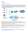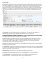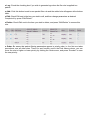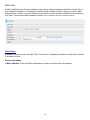
1
TW-EV901
VDSL2 Firewall Router
User Manual
Table of Contents
Chapter 1: Product..................................................................1
Introduction to your Router ................................................................ 1
Features .....................................................................................2
Chapter 2: Product Overview ................................................3
Package Contents ............................................................................3
Important Note for Using this Router ................................................ 4
Device Description ...........................................................................5
The Front LEDs ..........................................................................5
The Rear Ports ....................................................................... 6
Cabling ................................................................................................... 7
Chapter 3: Basic Installation .................................................8
Applications of the device..................................................................... 9
Network Configuration .................................................................. 10
Configuring PC in Windows 7 ................................................... 10
Configuring PC in Windows Vista............................................. 12
Configuring PC in Windows XP ................................................ 14
Configuring PC in Windows 2000 ............................................ 15
Configuring PC in Windows 95/98/Me ..................................... 16
Configuring PC in Windows NT4.0........................................... 17
Configuring Mac Osx ............................................................. 18
Factory Default Settings ..........................................................19
Information from your ISP……………………………………….20
Chapter 4: Configuration ..................................................... 21
Configuration via Web Interface...................................................... 22
Quick Start ..................................................................................... 23
Basic Status ...................................................................................... 27
Device Information ........................................................................... 27
Advanced Status ........................................................................... 28
Device Information .................................................................. 28
VDSL Status ......................................................................... 30
ARP Table .................................................................................... 31
DHCP Table………………………………………………….32
System Log ..................................................................................................33
Firewall Log .............................................................................34
UPnP Portmap ..................................................................... 35
Configuration ................................................................................... 36
LAN .................................................................................... 37
WAN ................................................................................... 40
System ............................................................................................48
Firewall ............................................................................................. 56
Virtual Server ........................................................................ 62
Switch-level QoS .................................................................. 68
Time Schedule ..................................................................... 71
Advanced ............................................................................... 72
Save configuration to FLASH .............................................................84
Restart ...................................................................................................85
Logout ....................................................................................................86
Chapter 5: Troubleshooting ................................................. 87
Appendix: Product Support & Contact ................................. 88
Chapter 1: Product
Introduction to your Router
Thank you for purchasing TW-EV901 Router. Your new router is an all-in-one VDSL2/Broadband
Router. It is designed for home and SOHO users who seek for high-speed broadband access with
VDSL2. The SOHO Firewall is integrated to provide protection against hacker attacks while the
Quality of Service prioritizes queues and traffic for applications such as music downloads, online
gaming, video streaming and file sharing.
Very High-speed Connectivity for Internet Access and IPTV Service
The TW-EV901 is a single VDSL2 port router equipped with four Ethernet ports by embedded
10/100Mbps Ethernet Switch. Compliant with ITU-T G.993.2 (VDSL2) , G.994.1 (handshake) and
G.997.1 (Physical layer management for digital subscriber line) VDSL2 standard, theTW-EV901
interoperates with major chipsets, and supports Profile 30a with line rate up to 100Mbps/100Mbps
for various bandwidth-consuming applications, like video streaming or Video on Demand.
Standard-compliant to ITU-T G.993.2, G.994.1 and G.997.1
TheTW-EV901 complies with the international standards and interoperates with other major/open
chipsets. It supports different profiles (8a, 8b, 8c, 8d, 12a, 12b, 17a, and 30a); different band plans
(997, 998, and proprietary) and different annex types (Annex A, Annex B and Annex C), by factory
settings to fit into different requirements.
Firewall Security and Smooth Traffic
With the built-in NAT default firewall, the advanced anti-hacker pattern-filtering protection features
automatically detect and block Denial of Service (DoS) attacks. In addition, Packet Filtering
provides high-level security for access control. Quality of Service Control prioritizes the traffic and
allows users to enjoy smooth traffic while running applications such as P2P or multimedia through
the Internet.
Easy Network Management
The Web-based User Interface of the TW-EV901makes it extremely easy for users to install
and manage the network. The router supports both DHCP client and server, enabling system
administrators to easily integrate this router into existing network environments, as well as manage
IP assignment without having to reconfigure other stations.
1
Features
Compliant with ITU-T G.993.2 , G.994.1 and G.997.1 VDSL2 Standard
VDSL2 Profiles: 8a/b/c/d, 12a/b, 17a, 30a
Band Plan 997 and 998 supported
Annex A, Annex B, Annex C supported
US0 Supported
OLR Supported
Compliant with VDSL2 MIB
Integrated 4-port Ethernet Switch
Ideal for LRE applications
SOHO Firewall Security with DoS
Prevention and Packet Filtering
Universal Plug and Play (UPnP) Compliant
Web-based Configuration
Quality of Service Control
Easy Network Management
2
Chapter 2: Product Overview
Package Contents
TW-EV901 Firewall Router
CD containing the on-line manual
RJ-11 xDSL / telephone cable
Ethernet (RJ-45) cable
Quick Start Guide
Power adapter
3
Important Note for Using this Router
4
Device Description
The Front LEDs
LED
Meaning
Lit red when the device is
booting. Lit green when the
1
Power
Lit when one of LAN ports is connected to an Ethernet device.
2
Ethernet port
1-4
(RJ-45 connector)
3
Bridge
Lit when device is configured as Pure Bridge mode, like modem
4
COT
Lit green when COT mode is selected
5
DSL
Lit green when the device is successfully connected to a VDSL
DSLAM. (“line sync”)
system is ready.
Lit red when WAN port fails to get IP address.
6
Lit green when WAN port gets IP address successfully.
Internet
Lit off when the device is in bridge mode or when WAN connection
absent.
5
The Rear Ports
Port
Meaning
1
Power Switch
Power ON/OFF switch.
2
Power
Connect it with the supplied power adapter.
3
Reset
4
Ethernet
Connect a UTP Ethernet cable (Cat-5 or Cat-5e) to one of the four LAN
ports when connecting to a PC or an office/home network of 10Mbps or
100Mbps.
5
DSL
Connect this port to the VDSL/telephone network with the RJ-11 cable
(telephone) provided.
Press this button for more than 5 seconds to restore the device to its default
mode. To change device to COT-mode press reset button until power led
turns to red.
6
Cabling
One of the most common causes of problems is because of bad cabling or VDSL line(s). Make
sure that all connected devices are turned on. On the front of the product is a bank of LEDs. Verify
that the LAN Link and VDSL line LEDs are lit. If they are not, verify that you are using the proper
cables.
Ensure that all other devices connected to the same telephone line as your router (e.g.
telephones, fax machines, analog modems) have a line filter connected between them and the
wall socket (unless you are using a Central Splitter or Central Filter installed by a qualified and
licensed electrician), and that all line filters are correctly installed in a right way. If line filter is not
installed and connected properly, it may cause problem to your VDSL connection or may result in
frequent disconnections.
7
Chapter 3: Basic Installation
The router can be configured through your web browser. A web browser is included as a standard
application in the following operating systems: Linux, Mac OS, Windows 98/NT/2000/XP/Me/Vista/7,
etc. The product provides an easy and user-friendly interface for configuration.
Please check your PC network components. The TCP/IP protocol stack and Ethernet network
adapter must be installed. If not, please refer to your Windows-related or other operating system
manuals.
There are ways to connect the router, either through an external repeater hub or connect directly
to your PCs. However, make sure that your PCs have an Ethernet interface installed properly prior
to connecting the router device. The default IP address of the router is 192.168.0.254 and the
subnet mask is 255.255.255.0 (i.e. any attached PC must be in the same subnet, and have an IP
address in the range of 192.168.0.1 to 192.168.0.253). The best and easiest way is to configure the
PC to get an IP address automatically from the router using DHCP. If you encounter any problem
accessing the router web interface, it is advisable to uninstall your firewall program on your PCs, as
they can cause problems accessing the IP address of the router. Users should make their own
decisions on what is the best to protect their network.
Please follow the following steps to configure your PC network environment.
8
Applications of the device
Deployment scenario for VDSL using FTTx
9
Network Configuration
Configuring PC in Windows 7
1. Go to Start. Click on Control Panel.
2. Then click on Network and Internet.
3. When the Network and Sharing
Center window pops up, select and
click on Change adapter settings
on the left window panel.
4. Select the Local Area Connection,
and right click the icon to select
Properties.
10
5. Choose Internet Protocol Version
4 (TCP/IPv4) and then click
Properties button.
6. In the TCP/IPv4 properties window,
select the” Use the following IP
address”. Type to IP address field
192.168.0.10 and to Subnet mask
field 255.255.255.0. Then click OK
to exit the setting.
7. Click OK again in the Local Area
Connection Properties window to
apply the new configuration.
11
Configuring PC in Windows Vista
1. Go to Start. Click on Network.
2. Then click on Network and Sharing
Center at the top bar.
3. When the Network and Sharing
Center window pops up, select and
click on Manage network connections on the left window column.
4. Select the Local Area Connection,
and right click the icon to select
Properties.
12
5. At the “Local Area Connection
Properties” Choose Internet Protocol
Version 4 (TCP/IPv4) and then click
“Properties” Button.
6. In the TCP/IPv4 properties window,
select the” Use the following IP
address”. Type to IP address field
192.168.0.10 and to Subnet mask
field 255.255.255.0. Then click OK
to exit the setting.
7. Click OK again in the Local Area
Connection Properties window to
apply the new configuration.
13
Configuring PC in Windows XP
1. Go to Start > Control Panel (in Classic
View). In the Control Panel, doubleclick on Network Connections
2. Double-click Local Area Connection.
3. In the Local Area Connection Status
window, click Properties.
4. Select Internet Protocol (TCP/IP) and
click Properties.
5. Select the “Use the following IP
address” Type to IP address field
192.168.0.10 and to Subnet mask
field 255.255.255.0
6. Click OK to finish the configuration.
14
Configuring PC in Windows 2000
1. Go to Start > Settings > Control Panel.
In the Control Panel, double-click on
Network and Dial-up Connections.
2. Double-click Local Area Connection.
3. In the Local Area Connection Status
window click Properties.
4. Select Internet Protocol (TCP/IP) and
click Properties.
5. Select the “Use the following IP
address”. Type to IP address field
192.168.0.10 and to Subnet mask field
255.255.255.0
6. Click OK to finish the configuration.
15
Configuring PC in Windows 95/98/Me
1. Go to Start > Settings > Control Panel.
In the Control Panel, double-click on
Network and choose the Configuration
tab.
2. Select TCP/IP > NE2000 Compatible,
or the name of your Network Interface
Card (NIC) in your PC.
3. Select the “Specify an IP address”.
Type to IP address field 192.168.0.10
and to Subnet Mask field
255.255.255.0. Then click OK button.
4. Then select the DNS Configurationtab.
5. Select the Disable DNS radio button
and click OK to finish the configuration.
16
Configuring PC in Windows NT4.0
1. Go to Start > Settings > Control Panel.
In the Control Panel, double-click on
Network and choose the Protocols tab.
2. Select TCP/IP Protocol and click Properties.
3. Select the “Specify an IP address” Type
to IP address field 192.168.0.10 and to
Subnet mask field 255.255.255.0 and
click OK.
17
Configuring Mac Osx
1. Go to System settings > Network
2. Configure iPv4 > choose
Manually
3. IP Address: 192.168.0.10
4. Subnet Mask: 255.255.255.0
5. Router: 192.168.0.254
6. DNS Server: 192.168.0.254
7. Click Apply
18
Factory Default Settings
Before configuring your router, you need to know the following default settings.
Web Interface (Username and Password)
Username: admin
Password: admin
The default username and password are “admin” and “admin” respectively.
Device LAN IP settings
IP Address: 192.168.0.254 Subnet
Mask: 255.255.255.0
ISP setting in WAN site
Pure Bridge
DHCP server
DHCP server is disabled.
If enabled, start IP Address: 192.168.0.100 IP pool
counts: 100
LAN and WAN Port Addresses
The parameters of LAN and WAN ports are pre-set in the factory. The default values are shown in
the table.
IP address
Subnet Mask
DHCP server function
IP addresses for
distribution to PCs
LAN Port
192.168.0.254
255.255.255.0
Enabled
100 IP addresses continuing
from 192.168.0.100 through
192.168.0.199
19
WAN Port
The DHCP function is
enabled to automatically get
the WAN port configuration
from the ISP.
Information from your ISP
Before configuring this device, you have to check with your ISP (Internet Service Provider) to find
out what kind of service is provided such as PPPoE, Obtain an IP Address Automatically (DHCP),
Fixed IP Address (Static IP).
Gather the information as illustrated in the following table and keep it for reference.
PPPoE
Username, Password, Service Name, and Domain Name System (DNS)
IP address (it can be automatically assigned by your ISP when you
connect or be set manually).
Obtain an IP Address
Automatically
DHCP Client (it can be automatically assigned by your ISP when you
connect or be set manually).
Fixed IP Address
IP address, Subnet mask, Gateway address, and Domain Name System
(DNS) IP address (it is fixed IP address).
20
Chapter 4: Configuration
To easily configure this device for internet access, you must have IE 7.0 / Chrome / Safari / Firefox
or above installed on your computer. You can configure the router through Web Interface
.
21
Configuration via Web Interface
Open your web browser and enter the default IP address of your router “192.168.0.254”; a log
in window prompt will appear. The default username and password are “admin” and “admin”
respectively. Click OK to enter the GUI.
Congratulations! You are now successfully log in the Router!
If the authentication succeeds, the homepage of Status will appear on the screen.
22
Quick Start
Whether on the Basic or Advanced Configuration Mode, click Quick Start to the WAN Port setup
pages.
Step 1
This screen displays some information for WAN port. Press “Continue” to proceed to the next
configuration page.
Connect mode: Show the current connection mode.
Protocol: Show the current protocol in the device. Default setting is the "Pure Bridge" mode.
Step 2
Click "Continue" to choose the Protocol to connect to the internet. There are 4 types of connection
protocols available for WAN connection. Each type of connection mode is described in the
following sections of WAN Connect mode (p. 25).
Step 3
After finishing the WAN port connection configuration, click "Continue" to proceed. The system will
upload and apply the new WAN port configuration to the device.
23
Note
If the Ethernet cable connected to the WAN port is not ready or there are problems for the
network access, there would be a signal indicated the failure for configuration...
Step 4
The configuration is successful.
24
WAN Connect Mode
There are 4 types of wireless connect modes: Obtain an IP Address Automatically Fixed IP
Address PPPoE connection and Pure Bridge
,
,
.
Obtain an IP Address
When connecting to the ISP, your router also functions as a DHCP client. The device can
automatically obtain an IP address, subnet mask, gateway address, and DNS server addresses if
the ISP assigns this information via DHCP. Select this protocol enables the device to automatically
get an IP address.
Fixed IP Address
Select this option to set static IP information. You will need to key in the information provided by
your ISP.
● IP Address: Enter your fixed IP address. Each IP address entered must be in the appropriate IP
form, which are four IP octets separated by a dot (x.x.x.x). The Router will not
accept the IP address if it is not in this format.
● Netmask: User can change it to others such as 255.255.255.128. Type the netmask assigned to
you by your ISP (if given).
● Gateway: Enter the IP address of the default gateway.
25
PPPoE
PPPoE (PPP over Ethernet) provides access control in a manner which is similar to dial-up services
using PPP.
● Username: Enter the username provided by your ISP. You can input up to 256 alphanumeric
characters (case sensitive). This is the format of username “username@ispname”
instead of “username”.
● Password: Enter the password provided by your ISP. You can input up to 32 alphanumeric
characters (case sensitive).
● Service Name: This item is for identification purposes. If it is required, your ISP will provide you
the necessary information. Maximum input is 32 alphanumeric characters.
● IP Address: Enter your fixed IP address. Leave the IP address as 0.0.0.0 to enable the device
to automatically obtain an IP address from your ISP.
● Authentication Protocol: Default is Auto. Please consult your ISP on whether to use Pap or
Chap.
● MTU: Maximum Transmission Unit. The size of the largest datagram (excluding media-specific
headers) that IP will attempt to send through the interface.
Pure Bridge
● If the device plays the role of the bridge between two network groups, select Pure Bridge.
26
Basic Status
Device Information
● Model Name: Provide a name for the router for the identification purpose.
● System Up-Time: The time record of how long the router is on.
● Software Version: The current firmware version of the device.
Physical Port Status
● Port Status: User can see which Ethernet port is connected to (the one with a check icon) and
the upstream and downstream speed the VDSL can support for users.
WAN
● Port: Name of the WAN connection.
● Protocol: The current protocol in the device. "Dynamic" means that the network is accessed by
DHCP.
● Operation: Operation on WAN port information.
● Connection: Current connection status.
● IP Address: WAN port IP address.
● Netmask: WAN port IP subnet mask.
● Gateway: IP address of the default gateway.
● Primary DNS: IP address of the primary DNS server.
27
Advanced Status
Device Information
● Model Name: Displays the name of this device.
● Host Name: Provide a name for the router for identification purposes. You can click Host Name
to change the router name and related setup.
● System Up-Time: The time record of how long the router is on.
● Current Time: Set the current time. Click "Current Time" to set the time in the Time Zone
section.
● Software Version: The current firmware version of this device.
● MAC Address: The LAN MAC address.
Physical Port Status
● Port Status: User can see which Ethernet port is connected to (the one with a check icon) and
the upstream and downstream speed the VDSL can support for users.
WAN
● Port: Name of the WAN connection. Click "EoVDSL" to enter WAN profile to set further WAN
information.
● Protocol: The current protocol in the device. "Dynamic" means that the network is accessed by
DHCP.
● Operation: Operation on WAN port information.
● Connection: Current connection status.
● IP Address: WAN port IP address.
28
● Netmask: WAN port IP subnet mask.
● Gateway: The IP address of the default gateway.
● Primary DNS: The IP address of the primary DNS server.
29
Status
VDSL Status
VDSL (Very High Bitrate DSL) is a DSL technology providing faster data transmission. It can
achieve incredible speeds and provides a complete home-communications/entertainment
package. The table below displays all the information for VDSL.
30
ARP Table
This table stores mapping information that the device uses to find the Layer 2 Media Access
Control (MAC) address that corresponds to the Layer 3 IP address of the device via the Address
Resolution Protocol (ARP) feature.
● IP Address: Shows the IP Address of the device that the MAC address maps to.
● MAC Address: Shows the MAC address that is corresponded to the IP address of the device it
is mapped to.
● Interface: Shows the interface name (on the router) that this IP address connects to.
● Static ARP: Shows the status of static ARP.
31
DHCP Table
The DHCP Table lists the DHCP leased information for all IP addresses assigned by the DHCP
server in the device.
● IP Address: The IP address which is assigned to the host with this MAC address.
● MAC Address: The MAC Address of internal DHCP client host.
● Client Host Name: The Host Name of internal DHCP client.
● Register Information: Shows the information provided during registration.
Click "IP Address" or go to "Configuration" for further configuration.
32
System Log
Display system log records of the device. You can trace the historical information with this function.
● Refresh: Click "Refresh" to update the system log.
● Clear: Click "Clear" to delete the system log records from the screen.
33
Firewall Log
Firewall Log displays the log information of any unexpected events that occurs to your firewall
settings. This page displays the router Firewall Log entries which record when you have enabled
Intrusion Detection or Block WAN PING in the Configuration – Firewall section of the interface.
Please see the Firewall section of this manual for more details on how to enable Firewall event
logging.
34
UPnP Portmap
This section lists all the established port-mapping using UPnP (Universal Plug and Play).
● Name: The Host Name of the internal UPnP client.
● Protocol: The connection protocol of the UPnP client.
● External Port: The external port for this connection.
● Internal Port: The internal port for this connection.
● IP Address: IP Address of the internal UPnP client.
35
Configuration
When you click this item, the column will expand to display the sub-items that will allow you to further
configure your router:
LAN WAN System Firewall Virtual Server Switch-level QoS Wake on LAN Time Schedule
and Advanced
,
,
,
,
,
,
,
.
The function of each sub-item in configuration is described in the following sections.
36
LAN
A Local Area Network (LAN) is a shared communication system network where many computers
are connected. This type of network is usually limited to a specific region within a building or just
within the same storey of a building.
There are 6 items within the LAN section: Ethernet IP Alias and DHCP Server
,
.
Ethernet
The router supports more than one Ethernet IP addresses in the LAN that supports multiple
internet access at the same time. Users usually have only one subnet in the LAN. The default IP
address for the router is 192.168.0.254.
● IP Address: The default IP Address of this router.
● Netmask: The default subnet mask of this router.
● RIP (Routing Information Protocol): RIP v1, RIP v2 Broadcast, RIP v2 Multicast and RIP
v1+v2 Broadcast. Check to enable RIP function.
Click "Apply" to confirm the settings.
37
IP Alias
This function allows the addition an IP alias to the network interface. It further allows user
the
flexibility to assign a specific function to use this IP.
● IP Address: Enter the IP address to be added to the network.
● Netmask: Specify a subnet mask for the IP to be added.
Click Apply to confirm the settings.
38
DHCP Server
DHCP allows networked devices to obtain information of IP Address, Netmask, Gateway as
well as DNS through the Ethernet Address of the device.
● DHCP Server: To configure the router‟s DHCP Server, select DHCP Server from the drop-down
menu in the DHCP Server Mode. You can then configure parameters of the DHCP Server including
the domain name, IP pool (starting IP address and ending IP address to be allocated to PCs on your
network), lease time for each assigned IP address (the period of time the IP address assigned will
be valid), DNS IP address and the gateway IP address. These details are sent to the DHCP client
(i.e. your PC) when it requests an IP address from the DHCP server. If you check “Use Router as
a DNS Server”, (usually the factory default setting), the Router acts as the DHCP server, assigning
the IP address to the local users configured as the DHCP clients in the LAN. Click Apply to enable
this function.
● DHCP Relay: If you select DHCP Relay from the drop-down menu in the “DHCP Server Mode”,
you must enter the IP address of the DHCP server you are going to use so that the Relay Agent will
assigns IP addresses to the DHCP client in the LAN. This function is only advised to use by your
network administrator or ISP. Click Apply to enable this function.
39
WAN
A WAN (Wide Area Network) is a computer network that covers a broad geographical area (e.g.
Internet) that is used to connect LAN and other types of network systems.
WAN Profile
Obtain an IP Address Automatically
When connecting to the ISP, your router also functions as a DHCP client. By configuring DHCP
settings, the device is able to obtain IP settings automatically from the ISP.
● Protocol: Select "Obtain an IP Address Automatically" in the drop-down menu.
● NAT: The NAT (Network Address Translation) allows one or more private IP addresses to be
mapped into a single public one. If users on your LAN have their own public IP addresses to
access the Internet, NAT function can be disabled.
● Obtain DNS (Domain Name System): Check the box to automatically obtain DNS.
● Primary DNS/ Secondary DNS: Enter the IP addresses of the primary and secondary DNS
servers. The DNS servers are passed to the DHCP clients
along with the IP address and the Netmask.
● MAC Spoofing: This option is required by some service providers. You must fill the MAC
address specified by your service provider when this information is required. It will temporarily
change your router‟s MAC address to the one you have specified in this field. The default setting is
“disable”.
● VLAN MUX: When enabled, the packets flowed on this WAN Profile will embed a VLAN
Tag. The VLAN ID and optional priority are specified in „802.1Q VLAN ID‟ and „802.1p Priority‟
Parameters. The received packets will forward to specific Ethernet port(s), either Untagged (VLAN
Tag is stripped) or Tagged (keep VLAN Tag).Oppositely, the packet that is going to forward to this
40
WAN Profile will add VLAN Tag if it does not have Tag yet. Click "Add" or “Set/Delete” to apply this
change. Then click „Apply‟ when all WAN Profiles are configured.
Fixed IP Address
A Static WAN connection will be configured according to the IP properties defined by your ISP.
● Protocol: Select "Fixed IP Address" in the drop-down menu.
● NAT: The NAT (Network Address Translation) allows one or more private IP addresses to be
mapped into a single public one. If users on your LAN have their own public IP addresses to
access the Internet, NAT function can be disabled.
● IP Address: Enter your fixed IP address. Each IP address entered in the field must be in the
appropriate IP form, which are four IP octets separated by a dot (x.x.x.x). The Router will not
accept the IP address if it is not in this format.
● Netmask: Type the Netmask assigned to you by your ISP (if given)
● Gateway: Enter the IP address of the default gateway (if given).
● Obtain DNS (Domain Name System): Check the box to automatically obtain DNS.
● Primary DNS/ Secondary DNS: Enter the IP addresses of the primary and secondary DNS
servers. The DNS servers are passed to the DHCP clients along with the IP address and the
Netmask.
● MAC Spoofing: This option is required by some service providers. You must fill the MAC
address specified by your service provider when this information is required. It will temporarily
change your router‟s MAC address to the one you have specified in this field. The default setting is
“disable”.
● VLAN MUX: When enabled, the packets flowed on this WAN Profile will embed a VLAN
Tag. The VLAN ID and optional priority are specified in „802.1Q VLAN ID‟ and „802.1p Priority‟
Parameters. The received packets will forward to specific Ethernet port(s), either Untagged (VLAN
Tag is stripped) or Tagged (keep VLAN Tag).Oppositely, the packet that is going to forward to this
41
WAN Profile will add VLAN Tag if it does not have Tag yet. Click "Add" or “Set/Delete” to apply this
change. Then click „Apply‟ when all WAN Profiles are configured.
PPPoE
PPPoE (PPP over Ethernet) provides access control in a manner which is similar to dial-up services
using PPP.
● Protocol: Select "PPPoE" in the drop-down menu.
● Username: Enter the username provided by your ISP. You can input up to 256 alphanumeric
characters (case sensitive). This is in the format of “username@ispname” instead of
simply “username”.
● Password: Enter the password provided by your ISP. You can input up to 32 alphanumeric
characters (case sensitive).
● Service Name: This item is for the identification purpose. If it is required, your ISP will provide
you the necessary information. Maximum input is 32 alphanumeric characters.
● NAT: The NAT (Network Address Translation) allows one or more private IP addresses to be
mapped into a single public one. If users on your LAN have their own public IP addresses
to access the Internet, NAT function can be disabled.
● IP (0.0.0.0. Auto): Enter your fixed IP address. Leave this section as “0.0.0.0” to automatically
obtain an IP address from your ISP.
● Auth. Protocol: Default is Auto. Please consult your ISP on whether to use Pap or Chap.
● Obtain DNS (Domain Name System): Check the box to automatically obtain DNS.
● Primary DNS/ Secondary DNS: Enter the IP addresses of the primary and secondary DNS
servers. The DNS servers are passed to the DHCP clients
along with the IP address and the Netmask.
42
● Connection: Click on Always On to establish a PPPoE session during start up and to
automatically re-establish the PPPoE session when disconnected by the ISP. You
may uncheck the item to disable this function.
● Idle Timeout: Auto-disconnect the broadband firewall gateway when there is no activity on the
line for a predetermined period of time.
● MTU: Maximum Transmission Unit. The size of the largest datagram (excluding media-specific
headers) that IP will attempt to send through the interface.
● MAC Spoofing: This option is required by some service Providers. You must fill the MAC
address specified by your service provider when this information is required. It will temporarily
change your router‟s MAC address to the one you have specified in this field. The default setting is
set to disable.
● VLAN MUX: When enabled, the packets flowed on this WAN Profile will embed a VLAN
Tag. The VLAN ID and optional priority are specified in „802.1Q VLAN ID‟ and „802.1p Priority‟
parameters. The received packets will forward to specific Ethernet port(s), either Untagged (VLAN
Tag is stripped) or Tagged (keep VLAN Tag). Oppositely, the packet that is going to forward to this
WAN Profile will add VLAN Tag if it does not have Tag yet. Should click "Add" or “Set/Delete” to
apply this change. Then click „Apply‟ when all WAN Profiles are configured.
43
Pure Bridge
● Protocol: Select "Pure Bridge" in the drop-down menu.
● MAC Spoofing: This option is required by some service providers. You must fill the MAC
address specified by your service provider when this information is required. It
will temporarily change your router‟s MAC address to the one you have
specified in this field. The default setting is set to disable.
● VLAN MUX: When enabled, the packets flowed on this WAN Profile will embed a VLAN
Tag. The VLAN ID and optional priority are specified in „802.1Q VLAN ID‟ and „802.1p Priority‟
parameters. The received packets will forward to specific Ethernet port(s), either Untagged (VLAN
Tag is stripped) or Tagged (keep VLAN Tag). Oppositely, the packet that is going to forward to this
WAN Profile will add VLAN Tag if it does not have Tag yet. Should click "Add" or “Set/Delete” to
apply this change. Then click „Apply‟ when all WAN Profiles are configured.
44
VDSL Port
This feature allows you to configure VDSL port to get connected to the Internet. There 2 operating
mode: CO (COT) and CPE (RT)
.
CO (COT)
● Operating Mode: Select the mode you will use. CO (COT): Central Office. CPE
(RT): Remote Terminal. The LED will light when selected as COT mode.
● Profile Enabled: The device provides most common VDSL2 profiles for user; it supports the 8a,
8b, 8c, 8d, 12a, 12b, 17a and 30a. You can select the proper profile for your
real environment.
● G.hs Carrier Set: Select the Carrier Set for G.hs protocol. Suggest to use „Auto‟ if not specified
by ISP or operator.
● Profile Adaptation/ Adaptation Length: When this feature is enabled, the CO device will
determine to use profile 17a or 30a to sync up depending on line length automatically. The
'Adaptation Length' is the estimated loop length that this 17a/30a switch happens. E.g. if length is
configured as 1500 feet, the device will use 30a if line is shorter than 1500 feet and use 17a if
longer than 1500 feet. The length is just rough reference. It depends on the line quality and line
condition a lot.
● Band Profile: Click on the drop-down menu and select the VDSL band plan to be used.
● ADSL Friendly: If ADSL/ADSL2/ADSL2+ service are co-existed in same copper loop and/or other
lines of same bundle, you can enable this function to reduce interference between ADSL and
VDSL signals. If the ADSL service is ADSL mode or ADSL2 mode, you can select 'Disable 1.1MHz'
option. If the ADSL service is ADSL2+ mode, please select 'Disable 2.2MHz' option. When this
function is in used, the VDSL2 downstream rate will reduce to a lower rate.
● Target SNR: The line quality is determined by using the SNR (Signal to Noise Ratio) and applies
to VDSL line connections only. The higher the SNR is, the better the line quality.
Click on the drop-down list and select the SNR margin value of Downstream or Upstream.
The range is from 6 dB to 24 dB and the default is 6 dB.
45
● Maximum Rate Limit: Configure the transmit rate of Maximum Upstream/Downstream. The
range is between 1Mbps to 101Mbps. The default is 101Mbp/s (bit per second).
● INP Symbol (30a) / INP Symbol (non-30a): Select from the drop-down menu and configure
the INP (Impulse Noise Protection) with specifying Upstream or Downstream to set minimum
protection values of port provision. The range is between 1 (or 0.5 for no 30a case) to 16 symbol
or No Protection. The default value is 2 symbols.
● Maximum Interleave Delay: The interleave process is use to correct data error before
modulation digital signal into analog signal. By configuring Maximum Interleave Delay, it can
prevent transmission delay caused of waiting data gathered. Select No delay to skip Interleave
process.
Click Apply to confirm the settings.
46
CPE (RT)
● Operating Mode: Select the mode you will use.
● Profile Enabled: The device provides most common VDSL2 profiles for user; it supports the
8a, 8b, 8c, 8d, 12a, 12b, 17a and 30a. You can select the proper profile depends on the real
environment.
● G.hs Carrier Set: Select the Carrier Set for G.hs protocol. Suggest to use „Auto‟ if not specified
by ISP or operator.
Click Apply to confirm the settings.
47
System
There are 6 items within the System section: Time Zone Firmware Upgrade Backup/Restore
Restart User Management and Mail Alert
,
,
,
,
.
Time Zone
The router does not have a real time clock on board; instead, it uses the Simple Network Time
Protocol (SNTP) to get the most current time from an SNTP server outside your network. Choose
your local time zone where the router is located from the drop-down menu, then click Enable.
After a successful connection to the Internet, the router will get the correct local time from the
SNTP server you have specified. If you prefer to specify an SNTP server other than those in the
drop-down list, simply enter the IP address in the”SNTP Server IP Address". Your ISP may also
provide an SNTP server for you to use. (Noted that Daylight Saving is only valid for specific areas)
Resync Period (in minutes) is the periodic interval the router will wait before it re-synchronizes
the router‟s time with that of the specified SNTP server. In order to avoid unnecessarily increasing
the load on your specified SNTP server you should keep the poll interval as high as possible – at
the absolute minimum every few hours or even days.
Click Apply to confirm the settings.
48
Firmware Upgrade
Your router‟s firmware is the software that enables it to operate and provides all its functionality
Assume your router as a dedicated computer, and the firmware as the software that runs in your
router. Thus, by upgrading the newly improved version of the firmware allows you to use newly
integrated features.
● Factory Default Settings: If select this setting, the device will reboot to restore the parameters
of all its applications to its default settings.
● Current Settings: If you select this setting, the device will reboot without dropping the existed
settings of all applications. Your previous configuration will be retained. Remember to press "Save
Config" to save your configuration before upgrading.
Click on Browse to select the new firmware image file you have downloaded to your PC. Once the
correct file is selected, click Upgrade to update the firmware of your router.
49
Backup / Restore
These functions allow you to save a backup of the current configuration of your router to a defined
location on your PC, or to restore a previously saved configuration. This is useful if you wish to
experiment with different settings, knowing that you have a backup in hand in case any mistakes
occur. It is advisable that you backup your router configuration before making any changes to your
router configuration.
Backup Configuration
Press Backup and select the location where your local PC will save the setting file to. You may
also want to change the name of the file when saving if you wish to keep multiple backups.
Restore Configuration
Press Browse to select a file from your PC to restore. You should only restore your router setting
by the Backup function which is created with the current version of the router firmware. Setting
files saved to your PC should not be manually edited in any way.
Select the settings files you wish to use, and press Restore to load the setting into the router. Wait
Do not perform any actions before the restoration has been finished.
50
Restart
There are 2 options for you to choose before restarting your TW-EV901 device. You can either
choose to restart your device with the Factory Default Settings or to restart the device with your
current settings. This function is quite useful if the configuration is changed to an undesirable
outcome, you can restart your device to Factory Default Setting.
If you wish to restart the router by using the factory default settings (for example, after a firmware
upgrade or if you have saved an incorrect configuration), select Factory Default Settings to reset
your device. Click Restart with option Current Settings to reboot your router (and restore your last
saved configuration).
After selecting the type of setting you want the device to restart with, click the Restart button to
initiate the process. After restarting, please wait several minutes to let the selected setting applied
to the system. You may also reset your router to factory settings by holding the small Reset pinhole
button more than 1 second on the back of your router.
51
User Management
In order to prevent unauthorized access to your router configuration interface, it requires all users
to login with a username and password. Therefore, only system administrator can access the
system.
This feature allows you to set up multiple user accounts which contains a unique password of its
own. In addition, you can also edit any existing user accounts or add new users to allow access to
the device configuration interface.
Edit Account Information
You can change the information of any account whether the account is active or valid.
1. To edit an account, click on the Edit radio button of the account you want to edit. Once selected,
all information of that account will be displayed.
2. Delete the information to be edited and replace it with the new one.
3. When it is done, simply click on the Edit/Delete button to save your changes.
Note
It is highly recommended that you change the password immediately to prevent security
breach to your GUI.
52
Add an account
1. Check the Valid checkbox, fill in all the information: User name, Password, Confirm Password,
Login Mode, and Level.
2. When it is done, click the Add button.
Delete a User Account
1. Check the Delete checkbox of the account you want to delete.
2. Then click the Edit/Delete button to confirm the deletion.
Note
You can delete any user account except for the default admin account. Thus, there is no
delete radio button available for this account.
53
Mail Alert
Mail Alert allows administrator to receive notifications from the router through email about
important events that is occurring in real time. This allows administrator to be able to take
immediate actions to counteract any possible hacking or to restore the router to its original status
should any failover / failback ever occurs.
Server Information
SMTP Server: Enter the SMTP (mail) server address.
Username: Enter the username of your SMTP server.
Password: Enter the password associated with the username.
Sender’s E-mail: Enter the email address you wish to send the mail alert email to.
WAN IP Change Alert
Recipient’s E-mail: Enter the email address you wish to send the WAN IP Change email to.
Intrusion Detection
Alert Mail Time: Set the time for sending the Alert mail.
Recipient’s E-mail: Enter the email address you wish to send the Intrusion Detection email to.
Click Apply to confirm the settings.
54
Firewall
Firewall and Access Control
TW-EV901 includes a full SPI (Stateful Packet Inspection) firewall for controlling Internet access
from your LAN as well as helping to prevent attacks from hackers. In addition, when using NAT
(Network Address Translation), the router acts as a “natural” Internet firewall, since all PCs on your
LAN use private IP addresses that cannot be directly accessed from the Internet. See the WAN
configuration section for more details on NAT.
Firewall: Prevent unauthorized access from outsiders to protect your local network.
NAT natural firewall: This masks LAN users‟ IP addresses, which are invisible to outside users on
the Internet, making it much more difficult for a hacker to target a machine on your network. This
natural firewall is on when the NAT function is enabled.
Firewall Security and Policy (General Settings): Inbound direction of Packet Filter rules prevent
unauthorized computers or applications accessing your local network from the Internet.
Intrusion Detection: Enable Intrusion Detection to detect, prevent, and log malicious attacks.
MAC Filter rules: Prevents unauthorized computers accessing the Internet.
A detailed explanation of each item shows in the Firewall section below: Packet Filter MAC
Filter Intrusion Detection Block WAN PING
,
,
,
.
55
Packet Filter
Packet filtering enables your router to block specific internal / external packets (by defining internal
and external IP address) from Internet access, or disable specific service requests (Port number)
to / from the Internet. This configuration program allows you to set up different filter rules for
different users based on their IP addresses or their network Port number. The relationship among
all filters is “or” operation, which means that the router checks these different filter rules one by
one, starting from the first rule. As long as one of the rules is satisfied, the specified action will be
taken.
● Rule Name: User defined description for entry identification. The maximum name length is 32
characters, and then can choose an application that they want from the listbox.
● Internal IP Address / External IP Address: This is the IP Address Filter used to allow or block
traffic to/from particular IP address (es). Input the IP range you want to filter out. If you leave these
four fields empty or enter 0.0.0.0, it refers to any IP address.
● Protocol: Specify the packet type (TCP, UDP, and TCP/UDP) that the rule applies to. Select
TCP if you wish to search for the connection-based application service on the remote server
using the port number. Or select UDP if you want to search for the connectionless application
service on the remote server using the port number.
● Action: If a packet matches this filter rule, forward (allows the packets to pass) or drop (disallow
the packets to pass) this packet.
● Internal Port: This Port or Port Range defines the ports allowed to be used by the Remote/WAN
to connect to the application. Default is set the range from 1 to 65535. It is recommended that this
option is configured by an advanced user.
● External Port: This is the Port or Port Range that defines the application.
● Direction: Determine whether the rule is for outgoing packets or for incoming packets.
● Time Schedule: It is self-defined time period. You may specify a time schedule for your
prioritization policy. For setup and detail, refer to Time Schedule section.
56
● Log: Check the checking box if you wish to generate logs when the filer rule is applied to a
packet.
● Add: Click this button to add a new packet filter rule and the added rule will appear at the bottom
table.
● Edit: Check Edit next to the item you wish to edit, and then change parameters as desired.
Complete it by press “Edit/Delete”.
● Delete: Check Edit next to the item you wish to delete, and press “Edit/Delete” to remove this
rule.
● Order: Be aware that packet filtering parameters appear in priority order i.e. the first one takes
precedence over all other rules. There is a sort function next to the Rule Name column, you can
move the rule to higher or lower priority by clicking the Order arrow, and press “Reorder” to save
the new priority.
57
MAC Filter
A MAC (Media Access Control) address is the unique network hardware identifier for each PC on
your network‟s interface (i.e. its Network Interface Card or Ethernet card). Using your router‟s MAC
Address Filter function, you can configure the network to block specific machines from accessing
your LAN. The format of MAC address could be: xx:xx:xx:xx:xx:xx or xx-xx-xx-xx-xx-xx.
Filter Action
● Action: Select an action for MAC Filter. This feature is disabled by default. Check Allow or Block
to activate the filter.
Server Information
● MAC Address: Enter the MAC addresses you wish to have the filter rule applied.
58
Intrusion Detection
The router Intrusion Detection System (IDS) is used to detect hacker‟s attack and intrusion
attempts from the Internet. If the IDS function of the firewall is enabled, inbound packets are
filtered and blocked depending on whether they are detected as possible hacker attacks, intrusion
attempts or other connections that the router determines to be suspicious.
● Intrusion Detection: Check Enable if you wish to detect whether intruders access your
computer without permission.
● Maximum TCP Open Handshaking Count: This is a threshold value to decide whether a SYN
Flood (a well known type of attack attempt) is occurring or not. Default value is 100 TCP SYN per
second.
● Maximum Ping Count: This is a threshold value to decide whether an ICMP Echo Storm is
occurring or not. Default value is 15 ICMP Echo Requests (PING) per second.
● Maximum ICMP Count: This is a threshold to decide whether an ICMP flood is occurring or not.
Default value is 100 ICMP packets per second except ICMP Echo Requests (PING).
● Log: Check Log if you wish to generate logs when the filer rule is applied to the Intrusion
Detection.
Click Apply to confirm the settings.
59
Table: Hacker attack types recognized by the IDS
Intrusion Name
Detect Parameter
Ascend Kill
Ascend Kill data
WinNuke
TCP
Port 135, 137~139,
Flag: URG
Blacklist Type of Block Drop Packet Show Log
Duration
Src IP
DoS
Yes
Yes
Src IP
DoS
Yes
Yes
Dst IP
Victim
Protection
Yes
Yes
Yes
Yes
Yes
Yes
Land attack
ICMP type 8
Des IP is broadcast
SrcIP = DstIP
Echo/CharGen
Scan
UDP Echo Port and
CharGen Port
Echo Scan
UDP Dst Port =
Echo(7)
Src IP
Scan
Yes
Yes
CharGen Scan
UDP Dst Port =
CharGen(19)
TCP Flag: X‟mas
Src IP
Scan
Yes
Yes
Src IP
Scan
Yes
Yes
Smurf
X’mas Tree Scan
IMAP
SYN/FIN Scan
TCP Flag: SYN/FIN
DstPort: IMAP(143)
SrcPort: 0 or 65535
Src IP
Scan
Yes
Yes
SYN/FIN/RST/ACK
Scan
TCP
No Existing session
And Scan Hosts more
than five.
Src IP
Scan
Yes
Yes
Net Bus Scan
TCP
No Existing session
DstPort = Net Bus
12345,12346, 3456
SrcIP
Scan
Yes
Yes
Back Orifice Scan
UDP, DstPort = Orifice
Port (31337)
SrcIP
Scan
Yes
Yes
SYN Flood
Max TCP Open
Handshaking Count
(Default 100 c/sec)
Yes
ICMP Flood
Max ICMP Count
(Default 100 c/sec)
Yes
ICMP Echo
Max PING Count
(Default 15 c/sec)
Yes
Src IP: Source IP
Src Port: Source Port Dst Port:
Destination Port Dst IP: Destination IP
60
Block WAN Ping
This feature is to be enabled when you want the public WAN IP address on your router not to
respond to any ping command.
This feature is disabled by default. To activate the Block WAN PING feature, check the Enable box
then click the Apply button.
61
Virtual Server
Virtual Server allows you to direct incoming traffic from WAN side (identified by Protocol and
External port) to the internal server with private IP address on the LAN side. The Internal port is
required only if the external port needs to be converted to a different port number used by the
server on the LAN side.
The device can be configured as a virtual server so that remote users accessing services such
as Web or FTP services via the public (WAN) IP address can be automatically redirected to local
servers in the LAN network. Depending on the requested service (TCP/UDP port number), the
device redirects the external service request to the appropriate server within the LAN network.
In TCP and UDP networks a port is a 16-bit number used to identify which application program
(usually a server) incoming connections should be delivered to. Some ports have numbers that
are pre-assigned to them by the IANA (the Internet Assigned Numbers Authority), and these are
referred to as “well-known ports”. Servers follow the well-known port assignments so clients can
locate them.
If you wish to run a server on your network that can be accessed from the WAN (i.e. from other
machines on the Internet that are outside your local network), or any application that can accept
incoming connections (e.g. Peer-to-peer/P2P software such as instant messaging applications and
P2P file-sharing applications) and are using NAT (Network Address Translation), then you need to
configure your router to forward these incoming connection attempts using specific ports to the PC
on your network running the application. You also need to use port forwarding if you wish to host
an online game server.
62
Example: List of some well-known and registered port numbers.
The Internet Assigned Numbers Authority (IANA) is the central coordinator for the assignment
of unique parameter values for Internet protocols. Port numbers range from 0 to 65535, but only
ports numbers 0 to 1023 are reserved for privileged services and are designated as “well-known
ports” (Please refer to Table below). The registered ports are numbered from 1024 through
49151. The remaining ports, referred to as dynamic or private ports, are numbered from 49152
through 65535.
Examples of well-known and registered port numbers are shown below, for further information,
please see IANA‟s website at: http://www.iana.org/assignments/port-numbers
.
For help on determining which private port numbers are used by common applications on this list,
please see the FAQs (Frequently Asked Questions) at our website.
Well-known and Registered Ports
Port Number
20
21
22
23
25
53
69
80
110
119
Protocol
TCP
TCP
TCP & UDP
TCP
TCP
TCP & UDP
UDP
TCP
TCP
TCP
Description
FTP Data
FTP Control
SSH Remote Login Protocol
Telnet
SMTP (simple Mail Transfer Protocol)
DNS (Domain Name Server)
TFTP (Trivial File Transfer Protocol)
World Wide Web HTTP
POP3 (Post Office Protocol version 3)
NEWS (Network News Transfer Protocol)
123
161
443
1503
1720
4000
7070
UDP
TCP
TCP & UDP
TCP
TCP
TCP
UDP
NTP (Network Time Protocol)
SNMP
HTTPS
T.120
H.323
ICQ
Real Audio
63
Port Mapping
Since NAT acts as a “natural” Internet firewall, your router protects your network from accessed
by outside users, as all incoming connection attempts point to your router unless you specifically
create Virtual Server entries to forward those ports to a PC on your network. When your router
needs to allow outside users to access internal servers, e.g. a web server, FTP server, Email
server or game server, the router can act as a “virtual server”. You can set up a local server with
a specific port number for the service to use, e.g. web/HTTP (port 80), FTP (port 21), Telnet (port
23), SMTP (port 25), or POP3 (port 110). When an incoming access request the router for a
specified port is received, it is forwarded to the corresponding internal server.
For example, if you set the port number 80 (Web/HTTP) to be mapped to the IP Address
192.168.0.2, then all incoming HTTP requests from outside users are forwarded to the local server
(PC) with the IP address of 192.168.0.2. If the port is not listed as a predefined application, you
need to add it manually.
In addition to specifying the port number used, you also need to specify the protocol used. The
protocol is determined by a particular application. Most applications use TCP or UDP; however,
you may also specify other protocols using the drop-down Protocol menu. Setting the protocol
to “all” causes all incoming connection attempts using all protocols on all port numbers to be
forwarded to the specified IP address.
● Application: Select the service you wish to configure.
● Protocol: A protocol is automatically applied when an Application is selected from the listbox
or you may select a protocol type you want. The protocol is used to be determined by a particular
application. Most applications will use TCP or UDP protocol.
● External Port & Internal Port: Enter the public port number & range you wish to configure.
● Internal IP Address: Enter the IP address of a specific internal server to which requests from
the specified port is forwarded.
● Time Schedule: Scheduling your prioritization policy.
● Add: Click to add a new virtual server rule. Click again and then the next figure will appear.
64
● Edit: Check the Edit radio button to display the parameter of the selected application, then after
changing the parameters click the Edit/Delete button to apply the changes.
● Delete: To remove a port mapping application, check the Delete box of the selected application
then click the Edit/Delete button.
65
DMZ
The DMZ (demilitarized zone) Host is a local computer exposed to the Internet. When setting a
particular internal IP address as the DMZ Host, all incoming unsolicited packets that do not use a
fixed port will be mapped to the Host in the LAN. Data will first be checked by the Firewall and
NAT algorithms before it is passed to the DMZ host.
Cautious: This Local computer exposing to the Internet may face various security risks.
● Time Schedule: Scheduling your prioritization policy.
Click Apply to confirm the settings.
66
ALG
This feature controls enable or disable various protocols over application layer.
SIP:
Enable: When SIP phone need ALG to pass through the NAT.
Disable: When SIP phone included NAT-Traversal algorithm. Turn off the SIP ALG.
This feature is disabled by default. To activate the ALG feature, check the Enable box then click
the Apply button.
67
Switch-level QoS
QoS helps you to control over the network traffic by prioritizing specific types of data traffic to certain
applications, maintaining stable performance of video or audio applications, and preventing traffic
delay or jitter. It facilitates your PC to control the quality and speed of throughput for each application
when the system is running with full load.
● QoS Mode: The default is Disable. Select “Strictly Priority” to let the high-priority packets pass
through before low-priority packets. “Weighted Round Robin (WRR)” refers to the number of higher
priority packets sent before the lower priority packets are sent in the queue. The default setting (in
Weight per Queue) is that the device sends 8 highest priority packets before sending 4 second high
priority packets, before sending 2 third high priority packets, and before sending the lowest priority
packets. The valid range is around 1 to 15.
68
● Port-based QoS: The default setting is Disable. Click Enable to activate this function and click
the radio button to set the priority for each port. There are 4 Ethernet ports could be configured.
Each port has 4 priority levels: High, Medium, Normal, Low; set the priority according to your needs,
and the packets that receive from the highest priority port will be the highest priority data.
● Frame-based QoS Four options can be selected. 802.1p only, TOS/DSCP only, 802.1p+TOS/
DSCP
:
● 802.1p only: 802.1p frame has eight priority rank (0~7) to classify the incoming packets with High,
Medium, Normal, and Low priority level.
● TOS/DSCP only: Classify traffic into different priority queue based on TOS/DSCP value
Differentiated Services Code Point (DSCP) is the first 6 bits in the ToS byte, which enables to code
for up to 64 different kinds of forwarding. DSCP Marking allows users to classify the traffic of the
application into different service classes to be executed according to the DSCP value.
● 802.1p+TOS/DSCP: Classify traffic into different priority queue based on both 802.1p value (if
presented) and/or TOS/DSCP value.
See DSCP Mapping Table
.
DSCP Mapping Table
69
Wake on LAN
WOL allows the router to set a command to turn on a particular computer (by specifying the MAC
Address) that can support this feature.
Entering the PC MAC Address and then click Add to save the setting.
Edit: Check the Edit radio button to display the parameter of the selected entry, then after
changing the parameters click the "Edit/Delete" button to apply the changes.
Delete: To remove a static route entry, check the Delete box of the selected entry then click the
"Edit/Delete" button.
70
Time Schedule
The Time Schedule supports up to 16 time slots which helps you to manage your Internet
connection. In each time profile, you may schedule specific day(s), i.e. Monday through Sunday to
restrict or allowing the usage of the Internet by users or applications.
This Time Schedule correlates closely with router‟s time, since router does not have a real time
clock on board; it uses the Simple Network Time Protocol (SNTP) to get the current time from an
SNTP server from the Internet. Refer to Time Zone for details. Your router time should correspond
with your local time. If the time is not set correctly, your Time Schedule will not function properly.
● Name: A user-defined description to identify this time portfolio.
● Day in a week: The default is set from Sunday through Saturday. You may specify the days for
the schedule to be applied.
● Start Time: The default is set at 8:00 AM. You may specify the start time of the schedule.
● End Time: The default is set at 18:00 (6:00PM). You may specify the end time of the schedule.
Click the Edit/Clear button to save your changes.
71
Advanced
Configuration options within the advanced section are for users who wish to take advantage of
the more advanced features of the router. Users who do not understand the features should not
attempt to reconfigure their router, unless advised to do so by support staff.
Here are the items within the Advanced section: Static Route Static ARP Dynamic DNS
Device Management SNMP Access Control and Remote Access
,
,
,
,
.
Static Route
With static route feature, you are equipped with the capability to control the routing of the all
the traffic across your network. With each routing rule created, you can specifically assign the
destination where the traffic will be routed to.
● Destination: Enter the destination IP where the traffic is to be forwarded.
● Netmask: Enter the Netmask of the destination.
● Gateway: Enter the gateway address for the traffic.
● Interface: Select an appropriate interface for the new routing rule from the drop down menu.
● Cost: This is the same meaning as Hop and represents the cost of transmission for routing
purposes. The number need not be precise, but it must between 0 and 65535; usually be left at 1.
Click Add to confirm the settings.
● Edit: Check the Edit radio button to display the parameter of the selected rule, then after
changing the parameters click the "Edit/Delete" button to apply the changes.
● Delete: To remove a static route entry, check the Delete box of the selected rule then click the
"Edit/Delete" button.
72
Static ARP
This feature allows you to map the layer-2 MAC (Media Access Control) address that corresponds
to the layer-3 IP address of the device. If you want a specific PC to use a fixed IP Address for a
particular purpose
● IP Address: Enter the IP of the device that the corresponding MAC address will be mapped to.
● MAC Address: Enter the MAC address that corresponds to the IP address of the device.
Click Add to confirm the settings.
● Edit: Check the Edit radio button to display the parameter of the selected application, then after
changing the parameters click the "Edit/Delete" button to apply the changes.
● Delete: To remove a static ARP entry, check the Delete box of the selected entry then click the
"Edit/Delete" button.
73
Dynamic DNS
The Dynamic DNS function lets you alias a dynamic IP address to a static hostname, so if your
ISP does not assign you a static IP address, you can still use a domain name. This is especially
useful when hosting servers via your WAN connection, so that anyone wishing to connect to you
may use your domain name, rather than the dynamic IP address which is assigned to you by ISP.
You need to first register and establish an account with the Dynamic DNS provider using their
website, for example http://www.dyndns.org/
.
Dynamic DNS: Default is disable. Check Enable to enable the Dynamic DNS function and the
following fields will be activated and required.
● Dynamic DNS Server: Select the DDNS service you have registered an account with.
● Wildcard: When enabled, you allow the system to lookup on domain names that do not exist to
have MX records synthesized for them.
● Domain Name, Username and Password: Enter your registered domain name and your
username and password for this service.
● Period: Enter the length of the period in the blank; you can set the period unit in day, hour or
minute. Click Apply to confirm the settings.
74
Device Management
The Device Management in advanced configuration settings allows you to control your router‟s
security options and device monitoring features.
Device Host Name
Host Name: Assign it a name.
Note
The Host Name cannot be used with one word only. There are two words should be
connected with a ‘.’ at least. For example:
Host Name: homegateway ==> Incorrect
Host Name: home.gateway or my.home.gateway ==> Correct
Embedded Web Server ( 2 Management IP Accounts)
● HTTP Port: This is the port number the router‟s embedded web server (for web-based
configuration) will use. The default value is the standard HTTP port, 80. Users may specify an
alternative if, for example, they are running a web server on a PC within their LAN.
● Expire to auto-logout: Specify a time length for the system to auto-logout from the
configuration session.
Example: User A enters 100 for HTTP port number, specifies 192.168.0.55 for his/her own IP
address, and sets the logout time to 3 minutes. The router will allow User A to access only
from the IP address 192.168.0.55 to logon to the Web GUI by typing: http://192.168.0.254:100
in their web browser. After 3 minutes, User A is logged out by the device automatically.
Universal Plug and Play (UPnP)
UPnP offers peer-to-peer network connectivity for PCs and other network devices, along with the
feature to control data transfer between devices. UPnP offers many advantages for users running
NAT routers through UPnP NAT Traversal, and on supported systems. By letting the application
control the required settings and removing the need for the user to control the advanced
configuration of their device will make tasks such as port forwarding become easier.
75
Both user‟s Operating System and its relevant applications must support UPnP in addition to the
router. Windows XP and Windows Me have a native built-in support for UPnP (when the component
is installed). Windows 98 users may have to install the Internet Connection Sharing client from
Windows XP in order to support UPnP feature. Windows 2000 does not support UPnP.
Disable: Inactive the router‟s UPnP functionality.
Enable: Check to active the router‟s UPnP functionality.
● UPnP Port: Default setting is 2869. It is highly recommended for users to use this port
value. If this value conflicts with other ports that have been used, you are allowed to change the
port number.
Click Apply to confirm the settings.
76
Installing UPnP in Windows Example
Follow the steps below to install the UPnP in Windows Me.
Step 1: Click Start and Control Panel. Double-click Add/Remove Programs.
Step 2: Click on the Windows Setup tab and select Communication in the Components selection
box. Click Details.
Step 3: In the Communications window, select the Universal Plug and Play check box in the
Components selection box.
77
Step 4: Click OK to go back to the Add/Remove Programs Properties window. Click Next.
Step 5: Restart the computer when prompted.
Follow the steps below to install the UPnP in Windows XP.
Step 1: Click Start and Control Panel.
Step 2: Double-click Network Connections.
Step 3: In the Network Connections window, click Advanced in the main menu and select Optional
Networking Components....
Step 4: When the Windows Optional Networking Components Wizard window appears, select
Networking Service in the Components selection box and click Details.
Step 5: In the Networking Services window, select the Universal Plug and Play check box.
78
Step 6: Click OK to go back to the Windows Optional Networking Component Wizard window and
click Next.
Auto-discover Your UPnP-enabled Network Device
Step 1: Click start and Control Panel. Double-click Network Connections. An icon displays under
Internet Gateway.
Step 2: Right-click the icon and select Properties.
Step 3: In the Internet Connection Properties window, click Settings to see the port mappings that
were automatically created.
79
Step 4: You may edit or delete the port mappings or click Add to manually add port mappings.
Step 5: Select Show icon in notification area when connected option and click OK. An icon
displays in the system tray.
80
Step 6: Double-click on the icon to display your current Internet connection status.
Web Configuration Easy Access
With UPnP, you can access web-based configuration for the device without first finding out the IP
address of the router. This helps if you do not know the router‟s IP address.
Follow the steps below to access web configuration.
Step 1: Click Start and then Control Panel.
Step 2: Double-click Network Connections.
Step 3: Select My Network Places under Other Places.
Step 4: An icon describing each UPnP-enabled device shows under Local Network.
Step 5: Right-click on the icon of this device and select Invoke. The web configuration login screen
displays.
Step 6: Right-click on the icon of this device and select Properties. A properties window displays
basic information.
81
SNMP Access Control
Software on a PC within the LAN is required in order to utilize this function – Simple Network
Management Protocol.
Parameters
● SNMP: Select Enable / Disable to activate / inactivate this function.
SNMP V1 and V2
● Read Community: Specify a name to be identified as the Read Community and an IP address.
This community string will be checked against the string entered in the configuration file. Once the
string name is matched, user obtains this IP address will be able to view the data.
● Write Community: Specify a name to be identified as the Write Community and an IP address.
This community string will be checked against the string entered in the configuration file. Once the
string name is matched, users from this IP address will be able to view and modify the data.
SNMP V3
Specify a name and password for authentication. And define the access right from identified IP
address. Once the authentication has succeeded, users from this IP address will be able to view
and modify the data.
Click Apply to confirm the settings.
82
Remote Access
To control the network access by defining the allowed IP Address ranges.
● Remote Access Control:
Enable: Select Enable to allow management access from remote side (mostly from internet).
Duration: Set how many minutes to allow management access from remote side. Zero (0)
means always on.
Click Apply to confirm the settings.
● Allowed Access IP Address Range:
Valid: Select Valid to allow remote management from these IP ranges.
IP Address Range: Specify the remote IP address which will be allowed to access device.
Clink Add to insert management IP address (es) to the list.
Click Add to confirm the settings.
83
Save configuration to FLASH
On the bottom right part, you can choose to save configuration, restart, or logout the system. After changing the router‟s configuration settings, you must save all of the configuration parameters
to FLASH to avoid losing them after turning off or resetting your router. Click “Save Config“and
Click “Apply” to write your new configuration to FLASH.
84
Restart
Click “Restart” with option Current Settings to reboot your router (and restore your last saved
configuration). If you wish to restart the router using the factory default settings (for example,
after a firmware upgrade or if you have saved an incorrect configuration), select Factory Default
Settings to reset to factory default settings
85
Logout
To exit the router web interface, click “Logout”. Please save your configuration setting before
logging out of the system. A Warning screen will appear as below.
Click OK and a message displays. Click Yes to close the window.
Be aware that the router configuration interface can only be accessed by one PC at a time.
Therefore, when a PC has logged into the system interface, the other users cannot access the
system interface until the current user has logged out of the system. If the previous user forgets to
logout, the second PC can only access the router web interface after a user-defined auto logout
period which is by default 3 minutes. You can however modify the value of the auto logout period
using the Advanced > Device Management section of the router web interface. Please see the
Advanced section of this manual for more information.
86
Chapter 5: Troubleshooting
If your router is not functioning properly, please refer to the suggested solutions provided in this
chapter. If your problems persist or the suggested solutions do not meet your needs, please kindly
contact your service provider for support.
Problems with the router
Problem
None of the LEDs lit when the router is
turned on
Suggested Action
Check the connection between the router and the
adapter. If the problem persists, it is most likely due
to the malfunction of your hardware. Please contact
your service provider for technical support.
You have forgotten your login username Try the default username & password (Please refer
or password
to Chapter 3). If this fails, restore your router to its
default setting by pressing the reset button for more
than 6 seconds.
Problem with LAN interface
Problem
Cannot PING any PC on LAN
Suggested Action
Check the Ethernet LEDs on the front panel.
The LED should be on for the port that has a PC
connected. If it does not lit, check to see if the
cable between your router and the PC is properly
connected. Make sure you have first uninstalled
your firewall program before troubleshooting.
87
88
Appendix: Product Support & Contact
If you come across any problems please contact the dealer from where you purchased your product.
TeleWell is a registered Trademark of TeleWell Oy
MAC OS is a registered Trademark of Apple Computer, Inc.
Windows 98, Windows NT, Windows 2000, Windows Me, Windows XP, Windows Vista and
Windows 7 are registered Trademarks of Microsoft Corporation.
89