1
ASCII BASIC
Coprocessor Module
User Manual for the HE693ASC900,
HE693ASC920 and HE693ASC940
7 MAY 2002
MAN0047-01
PREFACE
Page i
PREFACE
This manual explains how to use the ASCII BASIC I/O module and accompanying software for GE Fanuc Series
90 and CEGELEC Alspa 8000 family of Programmable Logic Controllers.
Copyright (c) 2002 Horner APG LLC., 640 N. Sherman Drive, Indianapolis, IN 46201. All rights reserved. No part
of this publication may be reproduced, transmitted, transcribed, stored in a retrieval system, or translated into any
language or computer language, in any form by any means, electronic, mechanical, magnetic, optical, chemical,
manual or otherwise, without the prior agreement and written permission of Horner Electric, Inc.
Information in this document is subject to change without notice and does not represent a commitment on the part
of Horner APG, LLC.
Series 90 and Logicmaster are trademarks of GE Fanuc Automation North America, Inc.
Alspa 8000 and P8 are trademarks of CEGELEC
MCS and Intel are trademarks of Intel Corporation
ProComm is a registered trademark of the Datastorm Corporation
WordPerfect is a trademark of WordPerfect Corporation
LIMITED WARRANTY AND LIMITATION OF LIABILITY
Horner APG, LLC. ("HE") warrants to the original purchaser that the ASCII BASIC module manufactured by HE is
free from defects in material and workmanship under normal use and service. The obligation of HE under this warranty
shall be limited to the repair or exchange of any part or parts which may prove defective under normal use and service
within two years from the date of manufacture or eighteen (18) months from the date of installation by the original
purchaser which every occurs first, such defect to be disclosed to the satisfaction of HE after examination by HE
of the allegedly defective part or parts. THIS WARRANTY IS EXPRESSLY IN LIEU OF ALL OTHER WARRANTIES
EXPRESSED OR IMPLIED INCLUDING THE WARRANTIES OF MERCHANTABILITY AND FITNESS FOR USE
AND OF ALL OTHER OBLIGATIONS OR LIABILITIES AND HE NEITHER ASSUMES, NOR AUTHORIZES ANY
OTHER PERSON TO ASSUME FOR HE, ANY OTHER LIABILITY IN CONNECTION WITH THE SALE OF THIS
ASCII BASIC MODULE. THIS WARRANTY SHALL NOT APPLY TO THIS ASCII BASIC MODULE OR ANY PART
HEREOF WHICH HAS BEEN SUBJECT TO ACCIDENT, NEGLIGENCE, ALTERATION, ABUSE, OR MISUSE. HE
MAKES NO WARRANTY WHATSOEVER IN RESPECT TO ACCESSORIES OR PARTS NOT SUPPLIED BY HE.
THE TERM "ORIGINAL PURCHASER", AS USED IN THIS WARRANTY, SHALL BE DEEMED TO MEAN THAT
PERSON FOR WHOM THE ASCII BASIC MODULE IS ORIGINALLY INSTALLED. THIS WARRANTY SHALL
APPLY ONLY WITHIN THE BOUNDARIES OF THE CONTINENTAL UNITED STATES.
In no event, whether as a result of breach of contract, warranty, tort (including negligence) or otherwise, shall HE
or its suppliers be liable for any special, consequential, incidental or penal damages including, but not limited to,
loss of profit or revenues, loss of use of the products or any associated equipment, damage to associated equipment,
cost of capital, cost of substitute products, facilities, services or replacement power, down time costs, or claims of
original purchaser’s customers for such damages.
To obtain warranty service, return the product to your distributor, with a description of the problem and in a suitable
package.
Page ii
PREFACE
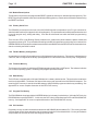
ABOUT THE PROGRAMMING EXAMPLES
The example programs and program segments in this manual and provided on the accompanying diskettes are
included solely for illustrative purposes. Due to the many variables and requirements associated with any particular installation, Horner APG cannot assume responsibility or liability for actual use based on the examples
and diagrams. It is the sole responsibility of the system designer utilizing the ASCII BASIC Module to appropriately design the end system, to appropriately integrate the ASCII BASIC Module and to make safety provisions
for the end equipment as is usual and customary in industrial applications as defined in any codes or standards
which apply.
The programming examples shown in this manual
have not been tested with the ASC900, ASC920 or
the ASC940. Contact Horner APG Tech Support for
specific help on an example or for an updated manual
when available at (317) 916-4274.
PREFACE
Page iii
TABLE OF CONTENTS
CHAPTER 1: INTRODUCTION
1.1
1.2
ASCII BASIC Module features
Hardware description .
1.2.1
1.2.2
1.2.3
1.2.4
1.2.5
1.2.6
1.2.7
1.2.8
1.2.9
.
.
Microprocessor .
.
Module Reset Options .
Primary Serial Port
.
Flexible Memory Configuration
Firmware Memory
.
Data Memory
.
Program File Memory .
PLC interface
.
Secondary Serial Port .
.
.
.
.
.
.
Page 1-1
Page 1-1
.
.
.
.
.
.
.
.
.
.
.
.
.
.
.
.
.
.
.
.
.
.
.
.
.
.
.
Page 1-1
Page 1-2
Page 1-2
Page 1-2
Page 1-2
Page 1-2
Page 1-2
Page 1-2
Page 1-3
.
.
.
.
.
.
Page 2-1
Page 2-1
.
.
Page 2-1
Page 2-2
CHAPTER 2: INSTALLATION
2.1
2.2
Module Placement
The "Console" Device
2.2.1
2.2.2
2.3
.
.
.
.
Using a Host Computer .
.
.
TERM - Dumb Terminal Emulation Software
Configuring the PLC
.
.
.
.
.
Page 2-2
CHAPTER 3: BASIC PROGRAMMING OVERVIEW
3.1
3.2
3.3
3.4
What is BASIC?.
.
Operating Modes
.
BASIC System Elements
.
.
.
.
.
.
.
.
.
.
.
.
Page 3-1
Page 3-1
Page 3-1
3.3.1
3.3.2
3.3.3
3.3.4
.
.
.
.
.
.
.
.
.
.
.
.
.
.
.
.
Page 3-1
Page 3-1
Page 3-1
Page 3-2
.
.
.
.
Page 3-2
Executable Statements .
Line Numbers .
.
BASIC Programs
.
Numeric Values .
.
Integer Values .
.
Floating-point Values
.
Numeric Constant Values
Operators
.
.
Variables
.
.
Array Variables .
.
Numeric Expressions .
Relational Expressions .
.
.
.
.
.
.
.
.
.
.
.
.
.
.
.
.
.
.
.
.
.
.
.
.
.
.
.
.
.
.
.
.
.
.
.
.
Page 3-2
Page 3-2
Page 3-3
Page 3-3
Page 3-3
Page 3-3
Page 3-3
Page 3-3
Page 3-4
Page 3-5
Page 3-5
Page 3-5
Stack Structure .
Control Stack .
Argument Stack .
The Line Editor .
BASIC Program Elements
3.4.1
3.4.2
3.4.3
3.4.4
3.4.5
3.4.6
3.4.7
3.4.8
3.4.9
3.4.10
3.4.11
3.4.12
Page iv
3.5
PREFACE
3.4.13 String Expressions
.
3.4.14 Special Function Operators
.
.
.
.
.
.
Page 3-5
Page 3-5
Manual Conventions
.
.
.
Page 3-6
.
.
CHAPTER 4: COMMANDS AND STATEMENTS
4.1
4.2
System Commands
.
.
.
.
.
Page 4-1
AUTORUN
BREAK@
CONT .
DELPGM
DIAG .
EDIT .
HELP .
LIST .
NEW .
NULL .
RESET .
RUN .
SAVE .
SELECT
STARTUP
STATUS
STEP .
.
.
.
.
.
.
.
.
.
.
.
.
.
.
.
.
.
.
.
.
.
.
.
.
.
.
.
.
.
.
.
.
.
.
.
.
.
.
.
.
.
.
.
.
.
.
.
.
.
.
.
.
.
.
.
.
.
.
.
.
.
.
.
.
.
.
.
.
.
.
.
.
.
.
.
.
.
.
.
.
.
.
.
.
.
Page 4-2
Page 4-2
Page 4-3
Page 4-4
Page 4-4
Page 4-5
Page 4-5
Page 4-5
Page 4-6
Page 4-6
Page 4-6
Page 4-6
Page 4-7
Page 4-7
Page 4-8
Page 4-8
Page 4-9
BASIC Statements and Operators
.
.
.
Page 4-10
4.2.1
4.2.2
4.2.3
4.2.4
4.2.5
4.2.6
4.2.7
4.2.8
4.2.9
.
.
.
.
.
.
.
.
.
.
.
.
.
.
.
.
.
.
.
.
.
.
.
.
.
.
.
Page 4-10
Page 4-10
Page 4-10
Page 4-10
Page 4-10
Page 4-11
Page 4-11
Page 4-11
Page 4-11
.
.
.
.
.
.
.
.
.
.
.
.
.
.
.
.
.
.
.
.
.
.
.
.
.
.
.
.
.
.
Page 4-12
Page 4-12
Page 4-12
Page 4-13
Page 4-13
Page 4-14
Page 4-14
Page 4-15
Page 4-16
Page 4-16
Page 4-17
Page 4-17
Page 4-18
Page 4-18
Page 4-19
.
.
.
.
.
.
.
.
.
.
.
.
.
.
.
.
.
Program Control Statements
Data Manipulation Statements
Serial Port Control Statements
Unary Operators
.
String Operators
.
Time Handling Operators
Special Function Operators
Configuration Statements
Logical Operators
.
DESCRIPTION OF STATEMENTS AND OPERATORS
ABS() .
.AND. .
ASC() operator
ASC() function
ATN() .
BCD() .
BNR() .
BREAK .
CHAIN .
CHR() .
CHR$() .
CLEAR .
CLEAR I
CLEAR S
CLOCK .
.
.
.
.
.
.
.
.
.
.
.
.
.
.
.
.
.
.
.
.
.
.
.
.
.
.
.
.
.
.
.
.
.
.
.
.
.
.
.
.
.
.
.
.
.
.
.
.
.
.
.
.
.
.
.
.
.
.
.
.
PREFACE
Page v
CLRMEM
.
.
CMDPORT
.
.
COMBRK
.
.
COS() .
.
.
CR
.
.
.
CTS
.
.
.
DATA .
.
.
DATE$ .
.
.
DELAY .
.
.
DIM
.
.
.
DO - UNTIL
.
.
DO - WHILE
.
.
END
.
.
.
ERC
.
.
.
EXP() .
.
.
FOR - TO - STEP - NEXT
FREE .
.
.
FTIME .
.
.
GOSUB - RETURN
.
GOTO .
.
.
IDLE .
.
.
IF - THEN - ELSE
.
INBUF$.
.
.
INKEY$.
.
.
INP() .
.
.
INPUT .
.
.
INSTR()
.
.
INT()
.
.
LCASE$()
.
.
LD@ .
.
.
LEFT$()
.
.
LEN() .
.
.
LET
.
.
.
LOG() .
.
.
MID$() .
.
.
MTOP .
.
.
NOT() .
.
.
ON - GOSUB .
.
ON - GOTO
.
.
ONERR
.
.
ONPORT
.
.
ONTIME
.
.
.OR.
.
.
.
OUT() .
.
.
PH0. .
.
.
PH1. .
.
.
PI
.
.
.
POP .
.
.
PRINT .
.
.
PUSH .
.
.
READ .
.
.
REM .
.
.
RESTORE
.
.
RETI .
.
.
RIGHT$()
.
.
.
.
.
.
.
.
.
.
.
.
.
.
.
.
.
.
.
.
.
.
.
.
.
.
.
.
.
.
.
.
.
.
.
.
.
.
.
.
.
.
.
.
.
.
.
.
.
.
.
.
.
.
.
.
.
.
.
.
.
.
.
.
.
.
.
.
.
.
.
.
.
.
.
.
.
.
.
.
.
.
.
.
.
.
.
.
.
.
.
.
.
.
.
.
.
.
.
.
.
.
.
.
.
.
.
.
.
.
.
.
.
.
.
.
.
.
.
.
.
.
.
.
.
.
.
.
.
.
.
.
.
.
.
.
.
.
.
.
.
.
.
.
.
.
.
.
.
.
.
.
.
.
.
.
.
.
.
.
.
.
.
.
.
.
.
.
.
.
.
.
.
.
.
.
.
.
.
.
.
.
.
.
.
.
.
.
.
.
.
.
.
.
.
.
.
.
.
.
.
.
.
.
.
.
.
.
.
.
.
.
.
.
.
.
.
.
.
.
.
.
Page 4-19
Page 4-20
Page 4-20
Page 4-21
Page 4-21
Page 4-21
Page 4-22
Page 4-22
Page 4-23
Page 4-23
Page 4-24
Page 4-24
Page 4-25
Page 4-25
Page 4-25
Page 4-26
Page 4-27
Page 4-27
Page 4-28
Page 4-28
Page 4-29
Page 4-30
Page 4-31
Page 4-31
Page 4-32
Page 4-32
Page 4-33
Page 4-34
Page 4-34
Page 4-34
Page 4-35
Page 4-35
Page 4-36
Page 4-36
Page 4-37
Page 4-37
Page 4-38
Page 4-38
Page 4-38
Page 4-39
Page 4-40
Page 4-40
Page 4-42
Page 4-42
Page 4-43
Page 4-43
Page 4-44
Page 4-44
Page 4-45
Page 4-45
Page 4-46
Page 4-46
Page 4-47
Page 4-47
Page 4-47
Page vi
PREFACE
RND .
RTRAP .
RTS
.
RUN operator
SETCOM
SETINPUT
SGN() .
SIN() .
SIZE .
SPC() .
SQR() .
ST@ .
STOP .
STRING
STR$() .
TAB() .
TAN() .
TIME .
TIME$ .
UCASE$()
USING()
VAL
.
XBY() .
.XOR. .
4.3
.
.
.
.
.
.
.
.
.
.
.
.
.
.
.
.
.
.
.
.
.
.
.
.
.
.
.
.
.
.
.
.
.
.
.
.
.
.
.
.
.
.
.
.
.
.
.
.
.
.
.
.
.
.
.
.
.
.
.
.
.
.
.
.
.
.
.
.
.
.
.
.
.
.
.
.
.
.
.
.
.
.
.
.
.
.
.
.
.
.
.
.
.
.
.
.
.
.
.
.
.
.
.
.
.
.
.
.
.
.
.
.
.
.
.
.
.
.
.
.
.
.
.
.
.
.
.
.
.
.
.
.
.
.
.
.
.
.
.
.
.
.
.
.
Page 4-48
Page 4-48
Page 4-49
Page 4-49
Page 4-50
Page 4-51
Page 4-52
Page 4-52
Page 4-52
Page 4-53
Page 4-53
Page 4-54
Page 4-54
Page 4-55
Page 4-56
Page 4-56
Page 4-57
Page 4-57
Page 4-58
Page 4-58
Page 4-59
Page 4-60
Page 4-60
Page 4-61
Interrupt Priority .
.
.
.
.
.
Page 4-62
CHAPTER 5: ARITHMETIC AND RELATIONAL OPERATORS
5.1
Operator precedence
.
.
.
.
.
Page 5-1
5.2
Arithmetic Operators
.
.
.
.
.
Page 5-1
Addition Operator
.
Subtraction Operator
.
Multiplication Operator .
Division Operator
.
Exponentiation Operator.
.
.
.
.
.
.
.
.
.
.
.
.
.
.
.
Page 5-2
Page 5-2
Page 5-2
Page 5-2
Page 5-2
.
.
.
Page 5-3
.
.
.
.
.
.
.
.
.
.
.
.
.
.
.
.
.
.
Page 5-4
Page 5-4
Page 5-4
Page 5-4
Page 5-4
Page 5-5
.
.
.
.
.
.
.
.
.
Page 6-1
Page 6-1
Page 6-1
(+)
(-)
(*)
(/)
(**)
5.3
Relational Operators
(=)
(<>)
(>)
(<)
(>=)
(<=)
.
.
Equal Operator .
.
Not Equal Operator
.
Greater than Operator .
Less than Operator
.
Greater than or equal Operator
Less than or equal Operator
CHAPTER 6: STRING HANDLING
6.1
6.2
6.3
What are STRINGS?
.
Combining strings
.
How strings are stored .
.
.
.
PREFACE
6.4
Page vii
Strings in Relational Expressions
.
.
.
Page 6-2
.
.
.
Page 7-1
.
.
.
.
.
.
.
.
.
.
.
.
.
.
.
.
.
.
.
.
.
.
.
.
.
.
.
.
.
.
.
.
.
.
Page 7-1
Page 7-1
Page 7-1
Page 7-1
Page 7-2
Page 7-2
Page 7-2
Page 7-2
Page 7-2
Page 7-2
Page 7-2
Page 7- 3
Page 7-3
Page 7-3
Page 7-3
Page 7-3
Page 7-3
.
.
Page 7-4
.
.
.
.
Page 7-4
Page 7-4
.
.
.
.
.
.
.
.
Page 8-1
Page 8-1
Page 8-1
Page 8-2
.
.
.
.
.
.
.
.
.
.
.
.
Page 9-1
Page 9-2
Page 9-2
Page 9-3
Page 9-4
Page 9-4
.
.
.
.
.
.
Page A-1
Page A-3
Page A-5
CHAPTER 7: ERROR HANDLING
7.1
ERROR Messages
7.1.1
7.1.2
7.1.3
7.1.4
7.1.5
7.1.6
7.1.7
7.1.8
7.1.9
7.1.10
7.1.11
7.1.12
7.1.13
7.1.14
7.1.15
7.1.16
7.1.17
7.2
.
Invalid syntax
.
.
Invalid argument
.
.
Arithmetic underflow
.
.
Arithmetic overflow
.
.
Division by zero .
.
.
Out of data
.
.
.
Can't continue .
.
.
While programming
.
.
Argument stack overflow
.
Control stack overflow .
.
Internal stack overflow .
.
Array size exceeded or not specified
Memory allocation
.
.
Invalid line number
.
.
Only program 0 may be edited .
Nothing to save .
.
.
Specified program does not exist
Warning Messages
7.2.1
7.2.2
.
.
.
.
WARNING! Extra input ignored! .
WARNING! String length exceeded...
CHAPTER 8: THE PLC INTERFACE
8.1
8.2
8.3
8.4
ASCII BASIC register mapping .
Asynchronous program execution
Register usage .
.
.
Using a register "protocol"
.
.
.
.
.
CHAPTER 9: GETTING STARTED
9.1
9.2
9.3
9.4
9.5
9.6
Prepare to Use the Module
.
.
Entering a Simple Program
.
.
Saving a Program in DATA Memory
.
Using the PROGRAM FILE Memory
.
Running a Program From the PROGRAM FILE
Deleting a Program from the PROGRAM FILE
APPENDIX A: RS-232 SERIAL PORT WIRING
A.1
A.2
A.3
Primary Port Wiring
.
Secondary Port Wiring .
Modem Port Wiring
.
APPENDIX B: RESERVED WORD LIST
.
.
.
.
.
.
Page viii
APPENDIX C: CONFIGURATION JUMPERS
APPENDIX D: ASCII CHARACTER SET
APPENDIX E: MEMORY CONFIGURATIONS
APPENDIX F: TERM - DUMB TERMINAL EMULATION SOFTWARE USER'S MANUAL
PREFACE
CHAPTER 1 : Introduction
Page 1-1
CHAPTER 1: INTRODUCTION
Congratulations on your purchase of the Horner Electric ASCII BASIC Module! The ASCII BASIC Module is capable
of performing some very powerful features typically reserved for (more expensive) midsize Programmable Logic
Controllers ("PLCs"). Many applications where the module will be used as a stand-alone microcomputer or where
information will be passed between the programmable controller and the module, will allow more flexibility to the
system designer.
1.1 ASCII BASIC Module features
1.
Programmed via the BASIC programming language, very versatile instruction set.
2.
Eight 16-bit input and eight 16-bit output registers interfacing the ASCII BASIC module to the PLC.
3.
Very powerful floating-point math instructions, including logarithmic and trigonometric functions.
4.
Primary RS-232 communication port for connection to a "dumb" terminal or host computer for
program development.
5.
Secondary RS-232/RS-485 communication port for connection to an operator interface terminal,
printer, etc.
6.
Single slot usage, low power consumption, typically less than 130 mA (180 mA max) at 5VDC.
7.
Asynchronous program execution.
1.2 Hardware description
The ASCII BASIC Module that you have received utilizes state of the art electronic components on a four layer copperclad printed circuit board for electrically quiet operation. Two very important precautions should be observed while
handling the module;
1.
NEVER insert or remove the module into or out of the PLC unit while power is applied to the
backplane. If this practice is repeated, eventually the module WILL BE DAMAGED.
2.
ALWAYS observe reasonable static discharge precautions while handling the module. Touch a
grounded metal surface to discharge any static buildup before touching the module.
1.2.1 Microprocessor
At the heart of the ASCII BASIC Module lies the Dallas 80C320 microprocessor running at 22.1184 Megahertz. This
configuration yields an instruction execution time of slightly more than six million instructions per second (at the
assembly level). Internal to this chip are 256 bytes of user memory (most of which are used by the ASCII BASIC
firmware). The 80C320 can address up to 64 Kilobytes of external CODE memory (this is where the firmware resides),
and up to 64 Kilobytes of external DATA memory (this space is divided between DATA and PROGRAM space for
the ASCII BASIC module).
Page 1-2
CHAPTER 1 : Introduction
1.2.2 Module Reset Options
The 80C320 microprocessor is equipped with a RESET signal that, when active, inhibits all processing activity. This
RESET signal is generated for a short time immediately following power-up. Reset can be simulated in software using
the RESET command.
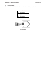
1.2.3 Primary Serial Port
The PRIMARY port located on the front of the ASCII BASIC Module incorporates a 9-pin "D" type connector for
standard cable interface (See Appendix A for wiring diagrams). This port features automatic baud rate detection and
is used for program entry, editing and debug. It can also be referenced from within the BASIC program during
execution.
There are two LED’s (Light Emitting Diodes) located on the module front panel behind the plastic window that
represent the primary port. They are labeled according to the RS-232 signal name to which they are connected, the
GREEN LED will illuminate whenever data is transmitted from the BASIC while the RED LED will illuminate whenever
data is received by the BASIC module.
1.2.4 Flexible Memory Configuration
As stated before, the 80C320 can address up to 128 Kilobytes of external memory. This memory is divided among
3 devices, and is configured at the factory (See Appendix E for a discussion of the "memory map" configuration).
1.2.5 Firmware Memory
The firmware site consists of a 64 Kilobyte EPROM mapped to the 80C320’s CODE space. The software in this site
is a "miniature operating system", controlling user program input and execution.
1.2.6 Data Memory
The DATA site is equipped with a 32K static RAM device in a battery-backed socket. This socket also contains the
real-time clock hardware. The lowest 1536 bytes of this memory are reserved for the ASCII BASIC interpreter. The
remaining DATA memory is used for all variable storage, AND for BASIC program number 0 entry and editing. See
Appendix E for a more complete discussion of the DATA FILE memory.
1.2.7 Program File Memory
The PROGRAM site is equipped with a 32K EEPROM device in a battery-backed socket. Unlike the DATA site, the
PROGRAM site may also be EMPTY. In this case, the DATA site is divided between DATA and PROGRAM FILE
memory. See Appendix E for a more complete discussion of the PROGRAM FILE memory.
1.2.8 PLC Interface
Proprietary circuitry is used in the interface between the ASCII BASIC Module and the PLC. This circuitry provides
32 bytes (eight 16-bit AI input and eight 16-bit AQ output) for both the PLC and the 80C320. Circuitry and software
are provided in the firmware to insure data integrity on both sides.
CHAPTER 1 : Introduction
Page 1-3
1.2.9 Secondary Serial Port
The ASCII BASIC Module is equipped with a secondary serial port. This port is multiplexed between RS-232, RS485 and modem (optional). The pinouts/connections for all three ports are shown in appendix A.
If the module that you have received is equipped with the modem option, it is documented in a separate publication
included with this document. The commands, statements and operators described in this manual that are used to
manipulate the auxiliary serial port will affect the RS-232 serial port, the RS-485 serial port and the modem in exactly
the same manner.
The module also has two LED’s located on the module front panel behind the plastic window for the auxiliary port.
They are labeled according to the RS-232 signal name to which they are connected, the GREEN LED will illuminate
whenever data is transmitted from the BASIC MODULE while the RED LED will illuminate whenever data is received
by the ASCII BASIC MODULE. For the modem option the GREEN LED represents off hook and the RED LED
represents on hook line activity (ring).
Page 1-4
CHAPTER 1 : Introduction
This page has intentionally been left blank.
CHAPTER 2 : Installation
Page 2-1
CHAPTER 2: INSTALLATION
2.1 Module Placement
The ASCII BASIC Module may be placed in any slot of the PLC backplane Follow the instructions in the PLC manual
for module insertion and removal.
2.2 The "Console" Device
To program the ASCII BASIC Module, the user must connect a "console" device to the primary RS-232 port This
device may be either a "dumb" terminal or a host computer running terminal emulation software Cable wiring diagrams
can be found in Appendix A The console device must be configured to a baud rate of 50 to 38,400 baud with no parity,
8 data bits and one stop bit Software (or XON/XOFF) handshaking is implemented by the ASCII BASIC Module’s
primary port upon initial power-up Once connected, follow these steps to initialize communications with the module;
1.
Apply power to the PLC rack.
2.
Press the SPACE bar on the console device The ASCII BASIC Module will automatically determine
the baud rate at which the space character (ASCII 32) was received and should respond with a full
screen of sign-on/status information;
If no response is obtained, or if the module responds erratically, recheck the cable wiring and communication
parameters, power cycle and try again.
The prompt characters "0>" are issued by the ASCII BASIC Module to indicate that it is in "command" mode and
is ready to accept commands The "0" indicates that program number 0 is currently selected.
2.2.1 Using a Host Computer
A host computer may be used as the console device, if a "terminal emulation" software program is available (such
as ProComm by DataStorm) There are two important points to be aware of when using such programs;
1.
Some terminal emulator programs send out characters when they are invoked If the ASCII BASIC
Module receives any character other than a space character (ASCII 32), the baud rate will be
incorrectly calculated and communications will not be possible To avoid this problem, configure and
initialize the terminal emulation program before applying power to the ASCII BASIC Module, then
press the space bar.
2.
Some terminal emulator programs do not support handshaking This means that it is very possible for
the ASCII BASIC Module to send data to the console device much faster than the host computer can
process it This may cause lost data, erroneous display of characters or even computer "lockup" If
software handshaking is not an available option for your terminal emulation software, use a lower baud
rate (to allow the terminal emulator program more time to process each character).
Page 2-2
CHAPTER 2 : Installation
2.2.2 TERM - Dumb Terminal Emulation Software
Included on the distribution diskette is a terminal emulation program called TERM.EXE This program may be loaded
and run on most any IBM PC or compatible computer This program was designed and written specifically for
communication with an ASCII BASIC Module and provides the following features;
1.
Software (XON/XOFF) and hardware (RTS/CTS) handshaking capability.
2.
Capable of communication rates of 110 to 57,600 baud.
3.
Complete program UPLOAD and DOWNLOAD capability at any baud rate (Programs created with
your favorite word processor may be downloaded).
2.3 Configuring the PLC
Before any I/O module can be accessed by the PLC, the "makeup" of the module must be defined inside the PLC.
This process is called "configuration." The ASCII BASIC Module configuration is supported by Logicmaster 90,
version 2.01 or later. Alternatively, the user may configure the PLC using the Hand-Held Programmer.
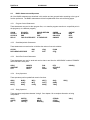
To configure the PLC for use with the ASCII BASIC Module, with the Hand-Held Programmer:
1.
Install the ASCII BASIC Module into the PLC as described in the PLC documentation, using the HandHeld Programmer as the programming device.
2.
Apply power to the PLC rack. The PLC will perform it's power-up diagnostics and a menu will appear
on the Hand-Held Programmer's display.
3.
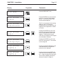
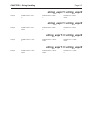
Enter the following key sequence on the Hand-Held Programmer.
Keystroke
Display
Comments
1. PROGRAM
2. DATA
<S
Press the MODE key to reach this
screen.
4 1. PROGRAM
2. DATA
<S
Press the 4 key, a 4 will appear as the
first character in the display.
R0:00 PLC
<S
KEY CLK : OFF
R0:01 EMPTY
<S
Press the ENTER key, the display will
now show the PLC CPU status.
Press the DOWN ARROW key until
the slot number containing the ASCII
BASIC Module appears following the
"R0:". This example assumes the
module resides in slot 1, therefore the
DOWN ARROW key is only pressed
once.
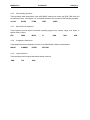
CHAPTER 2 : Installation
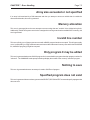
Keystroke
Display
R0:01 READ
<S
R0:01 ASC9XX
AI08:AI
<S
R0:01 ASC9XX <S
AI08:AI9-AI16
R0:01 ASC9XX
AQ08:9
Page 2-3
<S
Comments
Press the READ/VRFY key.
Press the ENTER key, this will cause
the PLC to "read" the ASCII BASIC
Module. The model number of the
module will be displayed.
The PLC now prompts for the starting
address of the 8 %AI registers.
Pressing the 9 key will cause the %AI
registers to be mapped from %AI009
to %AI016.
Pressing the ENTER key will cause
the PLC to accept the 9 and prompt
for the starting address of the %AQ
registers. Pressing the 9 key will
cause the %AI registers to be mapped
from %AQ009 to %AQ016.
R0:01 ASC9XX <S
AQ08:AQ9-AQ16
Pressing the ENTER key will cause
the PLC to accept the 9. The module
is now configured.
R0:01 ASC9XX
STARTUP:0
<S
Pressing the RIGHT ARROW key will
cause the additional configuration
parameter to be displayed.
R0:01 ASC9XX
STARTUP:0
<S
Pressing the 0 key then ENTER will
cause the STARTUP MODE to be set
to 0. 1 and 2 are also valid selections.
The STARTUP MODE parameter is
discussed in detail in chapter 4.
Page 2-4
CHAPTER 2 : Installation
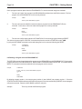
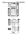
To configure the PLC for use with the ASCII BASIC Module, using Logicmaster 90:
1.
Install the ASCII BASIC Module into the PLC as described in the PLC documentation.
2.
Execute the Logicmaster 90 software.
3.
Enter the Configuration Package from the Main Menu <F2>.
4.
Select the proper folder.
5.
Choose I/O Configuration from the Configuration Menu <F1>.
6.
Cursor over to the slot containing the ASCII BASIC Module.
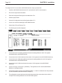
7.
Select Other <F8> and Foreign <F3>.
8.
The following screen will be displayed.
9.
Cursor down to the %AI starting address and enter the starting address for the 8 %AI registers
associated with the ASCII BASIC Module.
10.
Cursor down to the %AI size and enter the number of %AI registers for the ASCII BASIC Module (8).
11.
Cursor down to the %AQ starting address and enter the starting address for the 8 %AQ registers
associated with the ASCII BASIC Module.
12.
Cursor down to the %AQ size and enter the number of %AQ registers for the ASCII BASIC
Module (8).
13.
Cursor over to byte 1 and enter a 1 (00000001). This signifies to the PLC that the ASCII BASIC
Module is an intelligent module.
14.
Cursor down to byte 2 and enter the STARTUP MODE. 0, 1 and 2 are valid entries for this parameter.
(STARTUP MODE is discussed in detail in chapter 4.)
15.
The configuration screen should now look exactly the same as the screen shown above, with the
exception of the starting address for the %AI and %AQ registers.
CHAPTER 3 : Basic Programming Overview
Page 3-1
CHAPTER 3: BASIC PROGRAMMING OVERVIEW
3.1 What is BASIC?
BASIC is an acronym for "Beginner’s All-purpose Symbolic Instruction Code". It was created in 1964 by two
professors at Dartmouth University as a tool to teach the fundamentals of computer programming. It is an interactive
"interpreted" language, ideal for this industrial application. Those already familiar with the BASIC language should
have little difficulty programming the ASCII BASIC Module.
This manual is not a "How to Write Programs in BASIC" guide. The commands and statements available in the ASCII
BASIC Module are very adequately described and demonstrated in the examples. Hundreds of texts have been
written to teach good efficient BASIC programming, consult your local library.
3.2 Operating Modes
The ASCII BASIC Module operates in two states or "modes";
1. COMMAND MODE: Active whenever the prompt character ">" is present to signify that the module is ready to
accept commands and statements from the console device. No BASIC program is currently being executed. The
ASCII BASIC Module takes immediate action when a command is entered.
2. RUN MODE: Active whenever an ASCII BASIC program is currently being executed. Commands may not be
entered until the program is halted.
Some of the commands and statements may only be entered while in COMMAND mode, while some may only be
entered on BASIC program lines. Some may be used in both modes. The description of each command and
statement contains it’s allowable usage.
3.3 BASIC System Elements
3.3.1 Stack Structure
A "stack" is a dedicated area of memory used to store important information regarding program control and expression
evaluation. The ASCII BASIC Module incorporates the use of two software stacks.
3.3.2 Control Stack
The CONTROL STACK is used to store information regarding program control. The FOR-NEXT, DO-WHILE, and
GOSUB-RETURN statements will store information on the control stack for use at the "bottom" of each loop or
iteration. If too many of these statements are "active" or "nested" at one time, a Control stack error will result.
3.3.3 Argument Stack
The ARGUMENT STACK is used to store information while the module evaluates complex expressions. The PUSH
and POP statements also make use of the ARGUMENT STACK. If too many values are placed on the ARGUMENT
STACK, or the POP instruction is executed when no data is "on the stack", an Argument stack error is generated.
Page 3-2
CHAPTER 3 : Basic Programming Overview
3.3.4 The Line Editor
An ASCII BASIC command or program line may contain up to 79 characters. If an attempt is made to enter more
that 79 characters, the BELL character (ASCII 7) is transmitted from the module and the characters beyond the 79th
are ignored.
During line entry, the BACKSPACE character (ASCII 8) may be used to perform a "rubout" operation. This will cause
the last character entered to be erased from the line, while the cursor is placed at the position of the deleted character.
If there are no characters to "rubout" when the backspace key is pressed, a BELL character (ASCII 7) is sent from
the module and the rubout is ignored.
Once a line has been entered (CARRIAGE RETURN has been pressed), the program line can no longer be edited.
If any changes are to be made to the program line, the entire line must be reentered.
Blanks or spaces imbedded in statements (except for those in quoted strings and in REM statements) are ignored
by the ASCII BASIC Module. However, during the LISTing of programs, the module will insert spaces to improve
program readability.
If a CONTROL-S (ASCII 19) is inadvertently entered while the primary port is configured for
XON/XOFF handshaking, the module will appear to "lockup". This is because the
CONTROL-S character is the XOFF signal, which causes the module to cease transmission
until a CONTROL-Q (ASCII 17) is received. If this symptom occurs, try pressing
CONTROL-Q to resume module transmission.
3.4 BASIC Program Elements
3.4.1 Executable Statements
An ASCII BASIC program is comprised of statements. Every statement begins with a line number, followed by the
statement body, and terminated with a CARRIAGE RETURN <CR> (or a colon ":" in the case of multiple statements
per line).
3.4.2 Line Numbers
Every ASCII BASIC program line must begin with a line number ranging from 0 to 65535 inclusive. Line numbers are
used to order the program sequentially. In any one program, a line number can only be used once. Lines need not
be entered in numerical order, because the ASCII BASIC Module will automatically order them in ascending order.
For example, if the following program is entered non-sequentially;
example
0>10 PRINT "This is line 10"
0>30 PRINT "This is line 30"
0>20 PRINT "This is line 20"
0>RUN
This is line 10
This is line 20
This is line 30
CHAPTER 3 : Basic Programming Overview
Page 3-3
Notice that when the program was RUN, it was executed in numeric order, not in the order that the statements were
entered.
More than one statement may be placed on a single line if each statement is separated by a colon ":". Only one
line number may be used for a single line. For example;
example
0>10 PRINT "This is line 10" : PRINT "This is also line 10"
0>RUN
This is line 10
This is also line 10
If a line number is entered that already exists, the new line replaces the existing line. Therefore, to remove a line from
a program, simply enter the line number of the line to be deleted followed by a CARRIAGE RETURN <CR>.
3.4.3 BASIC Programs
BASIC programs are made up of one or more BASIC statements, each with a unique line number. When in
COMMAND mode, the BASIC program lines are entered via the console device. Up to 255 programs can be stored
in the ASCII BASIC module's memory. Note, however that only program number 0 can be edited. Program number
zero is stored in the DATA memory, all other programs are stored in the PROGRAM FILE memory. PROGRAM FILE
programs can be transferred into program 0 using the EDIT command and then re-saved in the PROGRAM FILE. The
COMMAND mode prompt will always specify which BASIC program is currently SELECTed.
3.4.4 Numeric Values
The ASCII BASIC Module is capable of manipulating numbers in four formats: Decimal integer (1234), hexadecimal
integer (89ABH), fractional floating-point (12.34) and exponential floating-point (12.345678 E+5).
3.4.5 Integer Values
Integers require two bytes of memory storage. There are several occasions when integer values are required. In these
cases, if a floating point value is used, it will be truncated to an integer, or an error will be generated.
Hexadecimal integers must always begin with a valid digit (0 through 9). For example, A0H should always be entered
as 0A0H.
3.4.6 Floating-point Values
Each floating point value requires six bytes of memory storage. The module will round all floating point numbers to
eight significant digits.
Exponential floating point values can range from +/- 1E-127 to +/- 99999999E+127.
3.4.7 Numeric Constant Values
Some commands and statements require the use of a CONSTANT argument. This means that a variable or
expression is not allowed. Constants can be floating point values but some cases will require integers.
3.4.8 Operators
An operator performs a predefined operation on variables and/or constants. Operators require either one or two
operands. Typical two operand or DYADIC operators include addition (+), subtraction (-), multiplication (*) and division
(/). Operators that require only one operand are often referred to as UNARY operators and include SIN(), COS() and
ABS().
Page 3-4
CHAPTER 3 : Basic Programming Overview
3.4.9 Variables
A VARIABLE is an area of memory that is referenced in BASIC statements by a user-defined NAME. Values may
be assigned to the variable, and the variable’s value can at any time be obtained.
Variable names must start with a letter (A to Z) and can contain up to 8 letters or numbers (including the underscore
character "_"). The following are examples of valid variable names;
FRED
VOLTAGE1
I3
AIR_CYL
Variables are allocated in a "static" manner. This means that each time a new variable is defined, BASIC will allocate
a portion of memory (8 bytes) specifically for that variable. This memory cannot be de-allocated on a variable by
variable basis. For example, if you execute a statement like "Q = 3", you cannot later tell BASIC that the variable
"Q" no longer exists and have the 8 bytes that are allocated to Q "freed up". The only way to clear the memory that
is allocated to a variable is to execute a CLEAR statement. This will "free up" all memory allocated to ALL variables.
Three very important anomalies should be observed when defining variable names;
1.
It takes BASIC longer to process variables whose names are greater than two
characters in length.
2.
Only the first character, the last character and the number of characters in the
variable name are significant. This means that the following variable names will
refer to the same memory space and are in essence the same variable (because
they all start with "I", end with "R" and contain 7 characters);
IN_CHAR
3.
ILLFOUR
INCDOOR
The user MAY NOT USE ANY BASIC KEYWORD as part of a variable name!
A BAD SYNTAX error will be generated if the user attempts to use a BASIC
reserved word as part of a variable name. The following variable names are invalid;
TABLE (uses TAB)
ONES (uses ON)
See appendix B for a list of all BASIC reserved words.
CRABS (uses ABS)
CHAPTER 3 : Basic Programming Overview
Page 3-5
3.4.10 Array Variables
The variables described up to this point are called SCALAR variables. Each variable name refers to only one 8-byte
memory entity. Variables may include a ONE DIMENSION subscript expression (ranging from 0 to 254) enclosed
in parentheses. This type of variable is referred to as a "dimensioned" or "array" variable. For example, an array called
MNTH might be used to contain the number of days in each month. The following program segment illustrates;
example
0>10 DIM MNTH(13) : REM Tells BASIC how much space to allocate for the MNTH array.
0>20 MNTH(1) = 31
0>30 MNTH(2) = 28
0>40 MNTH(3) = 31
0>50 MNTH(4) = 30
0>60 MNTH(5) = 31
0>70 MNTH(6) = 30
0>80 MNTH(7) = 31
0>90 MNTH(8) = 31
0>100 MNTH(9) = 30
0>110 MNTH(10) = 31
0>120 MNTH(11) = 30
0>130 MNTH(12) = 31
0>140 FOR X = 1 TO 12
0>150 PRINT "There are ", MNTH(X), " days in month ", X
0>160 NEXT X
3.4.11 Numeric Expressions
An expression is a logical mathematical formula that involves OPERATORS, CONSTANTS, and/or VARIABLES.
Expressions can be simple or quite complex.
example
12 * EXP(A) / 100
H(1) + 55
(SIN(A) * SIN(A) + COS(A) * COS(A) ) / 2
A stand-alone variable or constant is also considered an expression.
3.4.12 Relational Expressions
Relational expressions involve the operators EQUAL (=), NOT EQUAL (<>), GREATER THAN (>), LESS THAN (<),
GREATER THAN OR EQUAL (>=), and LESS THAN OR EQUAL (<=). They are used in control statements to "test"
a condition.
example
10 IF A<100 THEN B=5
Relational expressions ALWAYS require two numeric or string expressions.
3.4.13 String Expressions
String expressions are expressions that yield a character string result. Strings are fully discussed in chapter 6.
3.4.14 Special Function Operators
The special function operators available to the ASCII BASIC programmer are discussed in chapter 6. These operators
are used to assign and/or obtain values of predefined "special" values.
Page 3-6
CHAPTER 3 : Basic Programming Overview
3.5 Manual Conventions
The following conventions will be used in the remainder of this manual:
Special attention should be paid to the text following this symbol. If caution is not used,
irretrievable damage can be done to the module.
The command associated with this symbol can be used in COMMAND MODE.
The command associated with this symbol can be used in RUN MODE.
expr
Numeric expression, a logical mathematical formula that involves operators, (both unary and
dyadic), constants, and/or numeric variables. A "stand-alone" variable or constant is also
considered an expression.
integer
Numeric integer, Integers used by the ASCII BASIC module are whole numbers that range
from 0 to 65535 inclusive.
const
Numeric constant, a real number that ranges from +/- 1 E-127 to +/- .99999999 E+127. A
constant may be an integer.
line_num
BASIC line number, an integer value that refers to or assigns a BASIC program line number.
string_expr
String expression, a logical string formula that involves string operators, quoted strings, and/or
string variables.
[]
Optional parameter, objects appearing in square brackets are optional parameters and may
be omitted.
parameter
A parameter is an argument required by a BASIC operator or statement. Parameters will
always appear in italic print and will be fully described in the text for the operator or statement.
MAN0047-02
26 JAN 2001
PAGE 4-1
CH. 4
CHAPTER 4: COMMANDS AND STATEMENTS
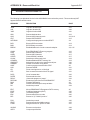
4.1
System Commands
The commands described in this section can only be executed while in "command" mode. Any attempt to
use these commands on a BASIC program line will cause an Invalid syntax error.
The following commands are discussed in this section;
AUTORUN
BREAK@
CONT
DELPGM
DIAG
EDIT
HELP
LIST
LIST#
NEW
NULL
RESET
RUN
SAVE
SELECT
STARTUP
STATUS
STEP
PAGE 4-2
CH. 4
26 JAN 2001
MAN0047-02
AUTORUN
SYNTAX : AUTORUN integer
The AUTORUN command is used to configure the program number that the ASCII BASIC Module will
automatically execute following a power-up or RESET condition. The integer is a numeric constant that
refers to the program number stored in the PROGRAM file memory. The integer may be any value
between 0 and 254 inclusive.
Note that the module must be placed in STARTUP mode 2 before it will run the specified program
following RESET.
If the integer value is zero, the program in DATA memory (program 0) will be executed following a
RESET. If this is desired, the CLRMEM 0 statement should be used to disable the DATA memory
initialization, retaining program 0 in DATA memory.
If the specified program does not exist following RESET, the module will default to STARTUP mode 1,
immediately displaying the sign-on/status message and entering COMMAND mode.
SEE ALSO:
STARTUP, RESET, CLRMEM
BREAK@
SYNTAX : BREAK@ line_num
The BREAK@ command is used to set a breakpoint on a BASIC program. Setting the breakpoint does
not alter the program, it merely configures the command interpreter to HALT whenever the specified
line_num is executed (similar to the STOP statement). The BREAK@ command has a significant
advantage over the STOP statement in that the breakpoint can be set without modifying the BASIC
program. Insertion of the STOP statement requires program modification, which makes the CONT
command invalid until the program is restarted. Using the BREAK@ command, the user can configure a
breakpoint and then execute the CONT command.
example
0>LIST
10
20
30
40
50
60
PRINT "This is line 10"
PRINT "This is line 20"
PRINT "This is line 30"
PRINT "This is line 40"
PRINT "This is line 50"
GOTO 10
Ready
0>BREAK@30
Ready
0>RUN
This is line 10
This is line 20
BREAK - In line 30
Ready
0>BREAK@10
0>CONT
This is line 30
This is line 40
This is line 50
BREAK - In line 10
MAN0047-02
26 JAN 2001
PAGE 4-3
CH. 4
Only one breakpoint may be active at any given time. If more than one breakpoint is required, then STOP
statements can be used. Note that when the program is halted due to breakpoint, BREAK is displayed
prior to the execution of the line number.
SEE ALSO :
CONT, STEP, STOP
CONT
SYNTAX : CONT
If an executing program is stopped by typing a CONTROL-C on the console device, or by the execution of
a STOP statement, program execution can be resumed from where it was interrupted by entering the
CONT command. While program execution is halted, the value of variables may be examined and/or
modified. The CONT command may not be used if the program has been modified or if the program was
terminated due to an ERROR.
example
0>10
0>20
0>30
0>RUN
1
2
3
FOR I = 1 TO 1000
PRINT I
NEXT I
<CONTROL-C TYPED ON CONSOLE DEVICE>
STOP! In Line 20
Ready
0>PRINT I
6
0>I=9999
0>CONT
9999
10000
SEE ALSO :
BREAK@, STEP, STOP
PAGE 4-4
CH. 4
26 JAN 2001
MAN0047-02
DELPGM
SYNTAX 1 : DELPGM integer
SYNTAX 2 : DELPGM *
The DELPGM command is used to erase one of the programs from the PROGRAM file memory. The
integer is a numeric constant that refers to the program number stored in the PROGRAM file memory.
The integer may be any value between 0 and 254 inclusive.
If the integer value refers to a nonexistent program in the PROGRAM file memory, a "Program does not
exist" error message is generated. If the integer value is zero, the program in DATA memory is erased.
This is exactly the same as entering the "NEW" command.
If the erased program was followed by one or more programs in the PROGRAM file, the subsequent
programs are "shifted" by one to "fill the gap". For example, if six programs are stored in the PROGRAM
FILE and the user erased program number 3 using the DELPGM command, programs 4, 5 and 6 would
be "moved" and would now be accessed as programs 3, 4 and 5 respectively.
Program 0 will always be SELECTed following a DELPGM command.
When an asterisk "*" is used as the argument to the DELPGM command, ALL of the programs stored in
the PROGRAM file memory are deleted! The module will display the following prompt prior to erasing the
programs;
Are you sure? (Y/N)
If a "Y" is entered, all programs in the PROGRAM file will be erased. If any other key is pressed in
response, the DELPGM command is ignored and the module will return to command mode. Note that the
DELPGM * command does not affect program 0 in DATA memory.
SEE ALSO :
EDIT, SAVE, SELECT
DIAG
SYNTAX : DIAG
The DIAG command invokes the ASCII BASIC Module’s firmware diagnostic routine. These diagnostic
routines will functionally test most of the circuitry on the ASCII BASIC Module.
When the DIAG command is entered, the module will respond with the following message;
ASCII Basic Module Firmware Diagnostics - V 3.00
(c) Copyright 1991-1995 Horner Electric, Inc.
The diagnostics will run continuously until any key is pressed.
Press Y to begin...
If the user types any key other than "Y", the ASCII BASIC module will return to command mode, and the
DIAG command is ignored. If the user types "Y" in response to the DIAG prompt, the firmware diagnostic
routines will run. The result of each test will be displayed as it is executed. When all tests have
completed, the tests are restarted from the beginning.
To terminate the diagnostic test execution, the user must simply press any key. At that point, the module
will behave as though it had just been reset. Note that any programs stored in the DATA memory will be
lost.
MAN0047-02
26 JAN 2001
PAGE 4-5
CH. 4
EDIT
SYNTAX : EDIT [integer]
The EDIT command transfers the program specified by the integer into program 0 (DATA memory) so
that it may be edited. If the integer is omitted, the currently selected program is transferred.
If program 0 (in DATA memory) exists when the EDIT command is issued, it will be overwritten by the
transferred program.
This command is most often used to place a PROGRAM FILE program into program 0 in DATA memory
for editing and debugging.
HELP
SYNTAX : HELP [keyword]
The ASCII BASIC module incorporates a very useful ON-LINE HELP system. If HELP is entered with no
argument, a full screen of information is displayed containing the HELP syntax and all of the BASIC
keywords implemented by the module.
If a keyword is specified following the HELP command, specific usage and syntax information is displayed
pertaining to the BASIC keyword.
Note that keywords should be entered EXACTLY as they appear in the HELP screen, including
parenthesis if required.
If an unrecognized keyword is entered following the HELP command, the HELP screen is displayed.
LIST
SYNTAX : LIST [#] [start_line_num] [-end_line_num]
The LIST command prints the current program to the console device. Note that the list command
"formats" the program in an easy to read manner. Spaces are inserted after the line number and before
and after statements. This feature is designed to aid in the debugging of ASCII BASIC programs.
The LISTing of a program may be terminated at any time by typing a CONTROL-C character on the
console device (unless the BREAK 0 option is in force).
If software handshaking (XON/XOFF) is being used, a LISTing may be paused by typing a CONTROL-S
character on the console device, and resumed by typing a CONTROL-Q.
If a start_line_num is specified, the program will be listed starting with the start_line_num and continuing
to the end of the program.
If a start_line_num and an end_line_num are specified, the program will be listed starting with the
start_line_num and continuing through the end_line_num.
If the # is used then the program listing will be directed to the designated AUXILIARY port.
SEE ALSO :
SETCOM
PAGE 4-6
CH. 4
26 JAN 2001
MAN0047-02
NEW
SYNTAX : NEW
When the NEW command is entered, the ASCII BASIC Module will delete program 0 in DATA memory.
All variables are set to zero and all strings are cleared. The real-time and millisecond clocks are not
effected. Generally, the NEW command is used to erase the RAM program and variables.
SEE ALSO :
DELPGM
NULL
SYNTAX : NULL [#] integer
The NULL command is used to output 0 to 255 NULL characters (ASCII 0) to the console device following
the transmission of a CARRIAGE RETURN character from the ASCII BASIC Module during COMMAND
mode. The addition of null characters can be used to provide additional time that might be required for a
printer to mechanically perform the carriage return operation. The number of null characters sent by the
module is initially zero.
The NULL command affects only the PRIMARY port, while the NULL# command is used to configure the
AUXILIARY port.
The NULL output option only operates while in COMMAND mode. To obtain the same functionality
during RUN mode, see the DELAY statement.
SEE ALSO :
DELAY
RESET
SYNTAX : RESET
The RESET command will effectively cause the module to perform a software RESET, just as though a
hardware reset or power-up had been performed. The RESET command has been provided as a means
to test the RESET options (STARTUP, AUTORUN, etc.) without having to manipulate the hardware.
SEE ALSO :
AUTORUN, STARTUP, BREAK, CLRMEM
RUN
SYNTAX : RUN
After RUN is typed, all variables are set equal to zero, any pending ONTIME interrupts are cleared and
program execution begins with the first line number of the selected program. The RUN command and the
GOTO statement are the only way the user can place the ASCII BASIC Module into the RUN mode from
the COMMAND mode. Program execution may be terminated at any time by typing a CONTROL-C
character on the console device.
Some BASICs allow a line number to follow the RUN command. The ASCII BASIC Module does not
permit such a variation on the RUN command, the RUN command will always cause execution to begin
with the first line number. To obtain the same functionality as the RUN[line_num] syntax, use the
GOTO[line_num] statement instead.
MAN0047-02
26 JAN 2001
PAGE 4-7
CH. 4
Note that variables and BASIC interrupts are not cleared if the CLRMEM 0 option is in force, and
CONTROL-C can be disabled using the BREAK 0 option.
SEE ALSO :
GOTO, RUN operator
SAVE
SYNTAX : SAVE [integer]
The SAVE command will copy the currently selected program into the specified program number in the
PROGRAM file.
The integer value must be between 1 and 254 inclusive. If no integer is specified, or if storing the
program using the specified number would leave a "gap" in program numbers, the program is copied into
the next available program space in the PROGRAM file. PROGRAM NUMBERS IN PROGRAM FILE
MEMORY WILL ALWAYS REMAIN CONTIGUOUS STARTING WITH PROGRAM NUMBER 1.
After SAVE is entered, the ASCII BASIC Module will respond with the program number that the stored
program will occupy in the PROGRAM file memory. This number is used when accessing the program
with the AUTORUN, SELECT, CHAIN, EDIT and DELPGM commands.
If the program number specified already exists in the PROGRAM file, the existing program and all
subsequent programs in the PROGRAM file are moved and the selected program will be "inserted" as
program number integer. For example, if there are 6 programs in the PROGRAM file (1 through 6), and
the currently selected program were SAVEd as number 4, programs 4, 5 and 6 in the PROGRAM file
would be moved to 5, 6 and 7 respectively, making room for the new program 4.
SEE ALSO :
DELPGM, AUTORUN, SELECT, EDIT, CHAIN
SELECT
SYNTAX : SELECT integer
The SELECT command causes the ASCII BASIC Module to select the specified program as the default
program. The integer specifies the program number assigned to the program when it was SAVED.
If an integer is specified for a program in the PROGRAM FILE that does not exist, a "Program does not
exist" error is generated. If no integer is specified, the module will default to program 0.
The SELECT command does not cause the specified program to be transferred into program 0. It is
possible to have several different programs in the PROGRAM FILE memory as well as a separate
program 0 in DATA memory.
When a program is SELECTed, it may be RUN or LISTed, but only program 0 may be edited. If an
attempt is made to modify a program in the PROGRAM FILE memory, an error will be generated.
Note that the COMMAND mode prompt will always contain a number that represents the currently
SELECTed program.
SEE ALSO :
SAVE, DELPGM, CHAIN, AUTORUN
PAGE 4-8
CH. 4
26 JAN 2001
MAN0047-02
STARTUP
SYNTAX : STARTUP integer
The STARTUP command is used to configure the behavior of the module following a power-up or RESET
condition. Valid integer arguments are described below;
STARTUP 0 : In this mode, the module will enter its automatic baud rate detection sequence following
RESET, waiting for a SPACE character (ASCII 32) to be transmitted to the PRIMARY serial port so that
the baud rate can be established. Once the SPACE character has been received, the module will display
the sign-on/status screen and enter COMMAND mode.
STARTUP 1 : In this mode, the module will configure the PRIMARY serial port with the last baud rate
used and will immediately display the sign-on/status screen following RESET and enter COMMAND
mode.
STARTUP 2 : In this mode, the module will configure the PRIMARY serial port with the last baud rate
used and will immediately run the BASIC program specified by the last AUTORUN command. If no
AUTORUN command has been issued, program 0 is assumed. If the specified program does not exist,
the module will revert to STARTUP mode 1.
The STARTUP value is accessible as a "configuration" parameter via the PLC programming device. This
feature is useful should the module be configured to run a BASIC program that implements the BREAK
function without providing a means to terminate the program. The STARTUP mode can be set to mode 0
or mode 1 to prevent the program from running following the next RESET.
SEE ALSO :
AUTORUN
STATUS
SYNTAX : STATUS
The STATUS command causes the ASCII BASIC Module to display a screen of useful information
regarding the current memory usage and some of the BASIC special function operators. A sample
STATUS display is shown below;
0>STATUS
DATA MEMORY:
32K bytes present, from 0 to 32767 (7FFFH).
No program exists in DATA memory, 1537 bytes occupied.
MTOP = 32767 (7FFFH).
31231 bytes free.
PROGRAM FILE MEMORY:
32K bytes present, from 32768 (8000H) to 65023 (FDFFH).
10 program(s) exist in PROGRAM FILE memory, 21452 bytes occupied.
10803 bytes free.
SYSTEM STATUS:
AUTORUN:
Program number for automatic execution is 0.
STARTUP:
Startup mode is set to 0.
BREAK: Control-C break checking is enabled.
CLRMEM:
Data memory initialization is disabled.
BAUD:
Stored primary port baud rate is 4800.
MAN0047-02
26 JAN 2001
PAGE 4-9
CH. 4
STEP
SYNTAX : STEP
The STEP command will cause the ASCII BASIC module to execute the next BASIC program line and
then halt, returning to COMMAND mode. This "single-step" operation provides a means of tracing
program execution.
If the current program has not yet been "RUN", or has been modified since the last halt, the STEP
command will cause the first program line to be executed. Otherwise, the next line is executed (the line
number displayed as a result of the BREAK@, STEP, or STOP execution).
Note that if multiple statements appear on the line to be executed (separated by colons ":"), all of the
statements on that line will be executed. The STEP command will follow program execution even if
control is passed using a GOTO or GOSUB statement. Whenever a new line number is encountered,
execution is halted and the line number of the next line to be executed is displayed.
example
0>LIST
10
20
30
40
50
PRINT "This is line 10"
PRINT "This is line 20"
PRINT "This is line 30"
PRINT "This is line 40"
GOTO 10
Ready
0>STEP
This is line 10
LINE-STEP - In line 20
Ready
0>STEP
This is line 20
LINE-STEP - In line 30
Ready
0>
Note that whenever program execution is halted due to the STEP command, the LINE-STEP is displayed
prior to the line number of the next line to be executed. When BREAK is displayed, the program was
halted because of a BREAK@ breakpoint, and STOP is displayed when execution is halted due to a
STOP statement or a control-C break.
SEE ALSO :
BREAK@, CONT, STOP
PAGE 4-10
CH. 4
4.2
26 JAN 2001
MAN0047-02
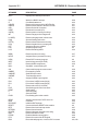
BASIC Statements and Operators
All of the BASIC statements are described in this section and are grouped below according to the type of
function performed. The BASIC statements are listed in alphabetical order on the following pages.
4.2.1
Program Control Statements
These statements are used to alter program flow, or to transfer program execution to a specified point in
the program (or to a different program).
CHAIN
CLEAR I
CLEAR S
DELAY
4.2.2
DO-UNTIL
DO-WHILE
END
FOR-TO-STEP-NEXT
GOSUB-RETURN
GOTO
IDLE
IF-THEN-ELSE
ONERR
ON-GOSUB
ON-GOTO
ONPORT
ONTIME
REM
RETI
STOP
Data Manipulation Statements
These statements are used to alter or initialize the values of numeric variables.
CLEAR
DATA-READ-RESTORE
4.2.3
DIM
LET
LD@
POP
PUSH
ST@
Serial Port Control Statements
These statements are used to send and receive data to and from the ASCII BASIC module’s PRIMARY
and AUXILIARY serial ports.
CHR()
CMDPORT
CTS
4.2.4
INBUF$
INKEY$
INPUT
PH0.
PH1.
PRINT
RTS
SETINPUT
TAB()
USING()
Unary Operators
These operators perform predefined numeric functions.
ABS()
ATN()
BCD()
4.2.5
BNR()
COS()
EXP()
INP()
INT()
LOG()
NOT()
OUT()
SGN()
SIN()
SQR()
TAN()
XBY()
String Operators
These operators manipulate character "strings". See chapter 6 for a complete discussion of string
manipulation.
ASC()
CHR$()
CR
INSTR()
LCASE$()
LEFT$()
LEN()
MID$()
RIGHT$()
STRING
STR$()
UCASE$()
VAL()
MAN0047-02
4.2.6
26 JAN 2001
PAGE 4-11
CH. 4
Time Handling Operators
These operators allow manipulation of the ASCII BASIC module’s two timers, the REAL-TIME clock and
the millisecond clock. See chapter 7 for a complete discussion of the module’s TIME handling capability.
CLOCK
4.2.7
DATE$
FTIME
TIME
TIME$
Special Function Operators
These operators provide specific information regarding program size, memory usage, error status, or
special numeric values.
ERC
4.2.8
FREE
MTOP
PI
RND
RUN
Configuration Statements
These statements allow configuration of some of the ASCII BASIC module’s characteristics.
BREAK
4.2.9
CLRMEM
RTRAP
SETCOM
Logical Operators
These operators perform logical and bitwise boolean functions.
.AND.
.OR.
.XOR.
SIZE
PAGE 4-12
CH. 4
26 JAN 2001
MAN0047-02
ABS()
SYNTAX : ABS(expr)
The ABS() operator returns the ABSOLUTE VALUE of the numeric expr.
example
0>PRINT ABS(5)
5
0>PRINT ABS(-5)
5
.AND.
SYNTAX 1 : var = expr1 .AND. expr2
SYNTAX 2 : rel_expr1 .AND. rel_expr2
For syntax 1, a bit-wise AND function is performed on the two expressions and the result is placed in the
var. Each binary bit of the two expressions is manipulated as shown in the truth table below;
EXPR1
0
0
1
1
example
0>PRINT 2.AND.3
2
EXPR2
0
1
0
1
RESULT
0
0
0
1
0>PH0. 55H.AND.0C0H
50H
For syntax 2, a logical AND function is performed on the two relational expressions. If BOTH relational
expressions are TRUE, a TRUE result (65535) is returned. If either relational expression is FALSE, a
FALSE result (0) is returned.
example
SEE ALSO :
0>PRINT (2=2).AND.(3=3)
65535
0>PRINT (2=3).AND.(3=2)
0
.OR., .XOR., NOT()
ASC() operator
SYNTAX : ASC(string_expr [,position])
The ASC() returns the numeric ASCII value of the character at the specified position in the string_expr. If
the position argument is omitted, the ASCII value of the first character in the string_expr is returned.
example
0>PRINT ASC("A")
65
0>STRING 257, 15
0>$(0)="Horner Electric"
0>PRINT CHR($(0),1), ASC($(0), 1)
H 72
MAN0047-02
26 JAN 2001
PAGE 4-13
CH. 4
In the following example, the ASCII value of each character in the string is displayed using the ASC
operator.
example
0>10 STRING 110, 10
0>20 $(0) = "ABCDEFGHIJK"
0>30 FOR I=1 TO 11
0>40 PRINT ASC($(0), I),
0>50 NEXT I
0>60 END
0>RUN
65 66 67 68 69 70 71 72 73 74 75
SEE ALSO :
CHR$(), STR$(), VAL()
ASC() function
SYNTAX : ASC(string_var, position) = char
The ASC() function will replace the character at the specified position in the string_var with the ASCII
character represented by the numeric expression represented by char.
example
0>10 STRING 110, 10
0>20 $(0) = "abcdefghijk"
0>30 PRINT $(0)
0>40 ASC($(0),1)=75
0>50 PRINT $(0)
0>60 ASC($(0),2)=ASC($(0),3)
0>70 PRINT $(0)
0>RUN
abcdefghijk
Kbcedfghijk
Kccedfghijk
SEE ALSO :
MID$(), ASC() operator
ATN()
SYNTAX : ATN(expr)
The ATN() Operator returns the trigonometric ARCTANGENT of the numeric expr. The argument is
expressed in radians an must be between +/- 200000. The calculation is carried out to 7 significant digits.
example
SEE ALSO :
0>PRINT ATN(PI)
1.2626272
COS(), SIN(), TAN(), PI
0>PRINT ATN(1)
.78539804
PAGE 4-14
CH. 4
26 JAN 2001
MAN0047-02
BCD()
SYNTAX : BCD(binary_expr)
The BCD() operator returns the BINARY CODED DECIMAL equivalent of the binary_expr. The
binary_expr is a valid numeric expression. Note that many values are invalid and cannot be converted to
BCD. For example, the values 10 through 15 would all return invalid BCD values. If an attempt is made
to convert an invalid binary_expr to BCD, an Invalid argument error is generated.
example
0>10 BINVAL = 85 : REM Initialize
0>20 PRINT BCD(BINVAL)
0>30 BINVAL = BINVAL+1
0>40 GOTO 20
0>RUN
55
56
57
58
59
ERROR! Bad argument! - In line 20
20 PRINT BCD(BINVAL)
———————————X
SEE ALSO :
BNR()
BNR()
SYNTAX : BNR(bcd_expr)
The BNR() operator returns the BINARY equivalent of the bcd_expr. The bcd_expr is a valid numeric
expression that solves to an integer value between 0 and 9999 inclusive. If an attempt is made to convert
an invalid BCD value, an Invalid argument error is generated.
example
SEE ALSO :
0>PRINT BNR(9999)
39321
BCD()
MAN0047-02
26 JAN 2001
PAGE 4-15
CH. 4
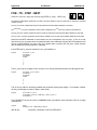
BREAK
SYNTAX : BREAK num
In normal operating conditions, the ASCII BASIC Module will halt program execution when a CONTROLC character (ASCII 3) is received at the PRIMARY serial port. This can cause problems under certain
circumstances. If the PRIMARY serial port is used to communicate with an external device during
program execution, the CONTROL-C character might be used in some sort of communication protocol. In
this case, the programmer must insure that the CONTROL-C character does NOT cause the ASCII
BASIC program to halt its execution. Additionally, the programmer may wish to disable the CONTROL-C
break feature to prevent end users from halting a program that utilizes an operator interface terminal.
The BREAK command is used to disable and enable the ASCII BASIC module’s CONTROL-C BREAK
feature.
BREAK 0
Following execution of the BREAK 0 statement, when a CONTROL-C character is
received by the ASCII BASIC module, program execution is NOT halted. If the
CONTROL-C character is received while the module is in COMMAND mode, the
CONTROL-C character is ECHOED to the transmitting device. The character is only
echoed during an INPUT statement if the character echo feature is enabled (See the
SETINPUT statement).
BREAK 1
Following execution of the BREAK 1 statement, when a CONTROL-C character is
received by the ASCII BASIC module, program execution is halted. The module will
assume this configuration following a RESET.
It is possible to configure a program to automatically run following RESET. If the program
immediately disables the CONTROL-C break feature and does not provide a means for reenabling it, THERE WILL BE NO WAY FOR THE PROGRAMMER TO STOP THE PROGRAM.
For this reason, the programmer should provide a means for re-enabling the CONTROL-C
interrupt from within the program.
There are several methods that may be incorporated to allow re-enabling of the CONTROL-C break
feature. Two methods are illustrated below.
example 1
THREE SECOND TIMEOUT:
0>10 TIME=0 : CLOCK1
0>20 IF INKEY$="" THEN END
0>30 IF TIME<=3 THEN 20
0>40 BREAK0
(Rest of program)
example 2
: REM Initialize the clock
: REM If a key is pressed, exit
: REM Wait for 3 seconds
: REM No key pressed, disable CTRL-C
PASSWORD:
0>10 STRING 257,15
0>20 BREAK0
0>30 $(0)="PASSWORD" : L=0
0>40 GOSUB 100 : $(1)=$(1)+INKEY$
0>50 IF LEN($(1)) < LEN($(0)) THEN 40
0>60 IF $(0)=$(1) THEN 80
0>70 $(1)="" : GOTO 40
0>80 BREAK 1 : GOTO 40
0>100
(Rest of program)
: REM Allocate string storage
: REM Disable CONTROL-C
: REM Define the password
: REM Read the keyboard
: REM If not enough chars, continue
: REM Otherwise, see if strings match
: REM If not, set input string to null
: REM Otherwise, enable CTRL-C
PAGE 4-16
CH. 4
26 JAN 2001
MAN0047-02
CHAIN
SYNTAX : CHAIN expr
The CHAIN statement will immediately transfer program control to the program specified by the numeric expr. The
specified program is executed starting at it’s first line number. If the specified program does not exist, the CHAIN
statement is ignored and execution will resume with the statement following the CHAIN statement.
The expr is a valid expression that solves to an integer value between 0 and 254 inclusive, any other value will cause
an Invalid argument error.
If the CLRMEM 0 option is in force, all string, array dimension and variable values are preserved between CHAINs. If
the CLRMEM 0 option is NOT in force, all variables and strings will be set equal to zero.
CHAIN will always clear any pending ONERR, ONTIME or ONPORT interrupts.
SEE ALSO :
CLRMEM
CHR()
SYNTAX 1 : CHR(expr)
SYNTAX 2 : CHR(string_var, position)
This operator is only included in the BASIC instruction set for compatibility with earlier versions of the
firmware. New programs should use the more versatile CHR$() operator.
Using syntax 1, the CHR() operator converts the numeric expr to an ASCII character (See Appendix D for
a list of the ASCII character set). The CHR() operator CAN ONLY BE USED WITHIN A PRINT
STATEMENT!
example
0>PRINT CHR(65)
A
Using syntax 2, the CHR() operator can also "pick out" characters from within an ASCII string. This is
done by including the string variable name within the parentheses of the CHR operator, followed by the
position of the character to "pick out".
example
0>$(0)=”Horner Electric”
0>PRINT CHR($(0),1)
H
In the following example, the string is displayed using the CHR operator, one character at a time. Then
the string is displayed in reverse.
example
SEE ALSO :
0>10 STRING 257,15
0>20 $(0) = "ASCII BASIC"
0>30 FOR I=1 TO 11
0>40 PRINT CHR($(0), I),
0>50 NEXT I
0>60 PRINT
0>70 FOR I=11 TO 1 STEP -1
0>80 PRINT CHR($(0), I),
0>90 NEXT I
0>100 END
0>RUN
ASCII BASIC
CISAB IICSA
ASC(), CHR$(), MID$()
MAN0047-02
26 JAN 2001
PAGE 4-17
CH. 4
CHR$()
SYNTAX : CHR$(expr)
The CHR$() operator returns a single character string whose ASCII value is expr (See Appendix D for a
list of the ASCII character set). The expr argument must solve to an integer value between 0 and 255
inclusive. The CHR$ operator may be used in any valid string expression.
example
0>PRINT CHR$(65)
A
0>PRINT "This is"+CHR$(20H)+CHR$(61H)+CHR$(20H)+"test"
This is a test
The CHR$() operator can also be used to imbed control characters inside string variables.
example
0>STRING 257,31
0>$(0)="Horner Electric"+CHR$(13)+CHR$(10)+"ASCII BASIC"
0>PRINT $(0)
Horner Electric
ASCII BASIC
SEE ALSO :
ASC(), CHR(), MID$()
CLEAR
SYNTAX : CLEAR
The CLEAR statement sets all variables equal to zero, sets all strings to NULL, and executes the
equivalent of the CLEAR I and CLEAR S statements. CLEAR does NOT reset the memory that has been
allocated for strings via the STRING statement, nor does it affect the real-time or millisecond clocks.
In general, the CLEAR statement is used to erase all variables.
example
0>10 X=1
0>20 CLEAR
0>30 PRINT X
0>RUN
0
SEE ALSO :
CLEAR I, CLEAR S, NEW, RUN, CLRMEM
PAGE 4-18
CH. 4
26 JAN 2001
MAN0047-02
CLEAR I
SYNTAX : CLEAR I
When the CLEAR I statement is executed, the ASCII BASIC Module will clear and disable the ONTIME
and ONPORT interrupts. This is used to disable the interrupts during specific sections of the user’s
BASIC program. This command does not affect the millisecond clock which is enabled by the CLOCK1
statement, it merely inhibits the interrupts. If the CLEAR I statement is used, the ONTIME and/or
ONPORT statements must be reissued before the interrupts will again be recognized.
example
0>10 TIME = 0 : CLOCK1
0>20 ONTIME TIME + 1, 100
0>30 IF INT(TIME) <> 3 THEN 30
0>40 CLEAR I
0>50 IF TIME > 6 THEN 20 ELSE 50
0>60 REM ** Timer interrupt subroutine. **
0>100 PRINT TIME
0>110 ONTIME TIME + 1, 100
0>120 RETI
0>RUN
1.005
2.005
3.005
7.005
8.005
SEE ALSO :
CLEAR, CLEAR S, NEW, RUN, CLRMEM
CLEAR S
SYNTAX : CLEAR S
The CLEAR S statement is used to reset the two ASCII BASIC Module stacks (the CONTROL stack and
the ARGUMENT stack, discussed in section 3.3). This statement can be used to "purge" the stack should
an unrecoverable error occur. Also, this statement can be used as an alternate means to exit a FORNEXT, DO-WHILE or DO-UNTIL loop.
example
SEE ALSO :
0>10 PRINT "Multiplication test, you have 5 seconds"
0>20 FOR I = 2 TO 9
0>30 N = INT(RND * 10) : A = N * I
0>40 PRINT "What is ", N, " * ", I, "?"
0>50 CLOCK1 : TIME = 0
0>60 ONTIME 5, 200 : INPUT R : IF R<> A THEN 100
0>70 PRINT "That’s right!" : NEXT I
0>80 PRINT "You did it! Good job." : END
0>100 PRINT "Wrong, try again..." : GOTO 50
0>200 REM ** Reset the control stack, too much time. **
0>210 CLEAR S : PRINT "You took too long..." : GOTO 10
CLEAR, CLEAR I, NEW, RUN, CLRMEM
MAN0047-02
26 JAN 2001
PAGE 4-19
CH. 4
CLOCK
SYNTAX 1 : CLOCK 1
SYNTAX 2 : CLOCK 0
The CLOCK1 statement is used to START the millisecond clock. After execution of the CLOCK 1
statement, the special function operator TIME is incremented once every 5 milliseconds. When the
millisecond clock is running, the ASCII BASIC program will execute at about 99.8% of its normal speed.
The CLOCK 0 statement is used to STOP the millisecond clock. After execution of the CLOCK 0
statement, the special function operator TIME is no longer incremented. Following a power-up or reset,
the millisecond clock is STOPPED.
SEE ALSO :
TIME, FTIME, ONTIME, TIME$, DATE$
CLRMEM
SYNTAX 1 : CLRMEM 0
SYNTAX 2 : CLRMEM 1
If the CLRMEM 0 statement is executed, the ASCII BASIC Module will NOT clear any of the DATA
memory following a power-up or RESET condition, or prior to running a CHAINed program. This option
allows the user to retain program 0 in DATA memory without the danger of “losing” the program following
a RESET.
If the CLRMEM1 statement is executed, the ASCII BASIC Module WILL clear DATA memory (up to
MTOP) following a power-up or RESET condition. This means that if program 0 exists in DATA memory it
will be lost, and the value of any variables will be initialized to zero following a power-up or RESET.
SEE ALSO :
CLEAR, CLEAR I, CLEAR S, NEW, RUN, CHAIN
PAGE 4-20
CH. 4
26 JAN 2001
MAN0047-02
CMDPORT
SYNTAX:
CMDPORT [#]
The CMDPORT statement is used to assign the programming console to the desired serial device. The
"console" is the port used for entering commands, statements and program lines. Initially, (following
RESET) the console is assigned to the PRIMARY serial device. Using the CMDPORT# statement, the
console can be assigned to the AUXILIARY serial device. When the AUXILIARY serial port is configured
as the console, all commands, statements and program lines are input via the AUXILIARY serial device.
All command mode transmission from the module is directed to the AUXILIARY serial device.
Note that all of the serial port control commands and statements (e.g. PRINT, INPUT, etc.) must still
incorporate the use of the "#" character in order to act upon the AUXILIARY serial device. The following
example assumes that the module is in it's initial state;
example
0>CMDPORT#
<The command port is now assigned to the AUXILIARY device>
After entry of the CMDPORT# command, the following sequence can be performed via the AUXILIARY
port;
example
Ready
0>10 REM This is a test line
0>LIST
Ready
0>LIST#
10 REM This is a test line
<The LIST command sent the output to the PRIMARY port>
<The LIST# command will send output to the AUXILIARY port>
When the CMDPORT statement is entered with no "#" parameter, the console device is assigned to the
PRIMARY port. If the CMDPORT# statement is entered and no AUXILIARY serial device is present, the
CMDPORT statement is ignored and the PRIMARY port will retain the console.
This feature could be used with the modem option to allow ASCII BASIC programming from a remote
location. To do this, the module would have to be programmed to establish the connection, at which point
a password routine could be implemented to allow the remote station access to the COMMAND mode.
COMBRK
SYNTAX : COMBRK
The COMBRK statement is a special operator that returns or detects a three character time break.
When used with the PRINT statement, the COMBRK function can be used to send the three character
break out one of the serial ports. This function is particularly useful when attempting to transfer SNP
protocol messages from one serial port to another.
The COMBRK operator may also be used to imbed a three character break inside a string variable.
SEE ALSO :
PRINT
MAN0047-02
26 JAN 2001
PAGE 4-21
CH. 4
COS()
SYNTAX : COS(expr)
The COS() operator returns the trigonometric COSINE of the numeric expr. The argument is expressed
in radians and must be between +/- 200000. The calculation is carried out to seven significant digits.
example
SEE ALSO :
0>PRINT COS(PI/4)
.7071067
0>PRINT COS(0)
1
ATN(), SIN(), TAN(), PI
CR
SYNTAX : CR
The CR statement is a special operator that returns a single CARRIAGE RETURN character (with no
LINE FEED). When used in the PRINT statement, the CR function can be used to create a line on the
console device that is repeatedly updated.
example
>10 FOR I=1 TO 1000
>20 PRINT I, CR,
>30 NEXT I
The CR operator may also be used to imbed a CARRIAGE RETURN character inside a string variable.
example
0> STRING 257,63
0> $(0)="
is hidden"+CR+"This string"
0> PRINT $(0)
This string is hidden
SEE ALSO:
CHR$()
CTS
SYNTAX : CTS [#]
The CTS operator is used to control the state of the hardware handshaking output on one of the two
serial ports. The CTS (Clear To Send) signal is pin 8 on the DB-9 connector. This signal can be
activated (to it’s "high" state) by setting it to a nonzero value;
example
0>CTS=1
0>PRINT CTS
65535
: REM Sets the PRIMARY port CTS line HIGH (+12V)
Likewise, the CTS signal can be deactivated (to it’s "low" state) by setting it to zero.
example
0>CTS#=0
0>PRINT CTS#
0
: REM Sets the AUXILIARY port CTS line LOW (-12V)
As shown in the example above, if a "#" character is appended to the CTS operator, the AUXILIARY port
CTS line is manipulated.
SEE ALSO:
RTS
PAGE 4-22
CH. 4
26 JAN 2001
MAN0047-02
DATA
SYNTAX : DATA expr [,expr ,expr ...]
The DATA statement specifies CONSTANT expressions that may be retrieved by a READ statement. If
multiple expressions are to be used for a single DATA statement, the expressions must be separated by
commas. More than one DATA statement may appear within the same program, in this case the
expressions in the DATA statements will appear to BASIC as one long DATA statement. DATA
statements may appear anywhere in the program, they are not executed and will not generate an error.
SEE ALSO:
READ, RESTORE
DATE$
SYNTAX : DATE$
The DATE$ operator is used to assign or retrieve a value to the REAL-TIME calendar. The real-time
clock/calendar continues to run and maintains the time/date even when power is removed from the ASCII
BASIC module.
When the DATE$ operator is used to retrieve the value of the real-time calendar, the date is returned in
the format shown below.
When the DATE$ operator appears on the left side of an assignment statement, a string variable or
constant that represents the date must appear on the right side. This string MUST be formatted as
follows;
MM/DD/YY
where MM is the month (01 to 12), DD is the day of the month (01 to 31) and YY is the year (00 to 99).
Delimiting characters (shown in the example as slashes) must appear between the arguments but may be
any character.
Leading zeros may NOT be omitted. This means that the following statement would generate an Invalid
argument error;
example
0>DATE$="1/1/90"
ERROR! Invalid argument!
Ready
0>DATE$="122590"
ERROR! Invalid argument!
Ready
The following are valid examples of DATE$ manipulation:
example
SEE ALSO:
0>DATE$="01/01/80"
0>DATE$="12-25-92"
CLOCK, TIME, TIME$, FTIME
MAN0047-02
26 JAN 2001
PAGE 4-23
CH. 4
DELAY
SYNTAX : DELAY(expr)
The DELAY() function will cause the module to pause for the number of milliseconds specified by the
numeric expr.
The following example program segment will update the DATE and TIME on the console device
approximately once per second.
example
SEE ALSO:
0>10 PRINT DATE$, " ", TIME$, CR,
0>20 DELAY(1000)
0>30 GOTO 10
: REM Display the current DATE/TIME
REM Wait for one second
: REM Go update the DATE/TIME again
ONTIME, ONPORT
DIM
SYNTAX : DIM var(expr) [var(expr), var(expr)...]
The DIM statement reserves memory storage space for ARRAY variables. ARRAY variables may be
assigned a ONE DIMENSION subscript which may not exceed 254. Once a variable has been
DIMensioned in a program, it may not be re-DIMensioned. If this is attempted, an array size error will be
generated.
If an arrayed variable is used that has NOT been dimensioned using a DIM statement, the maximum
subscript for the array is 9 (10 elements, 0 through 9). All arrays are set equal to zero whenever a NEW
or CLEAR command are executed. If the CLRMEM 1 option is in force, all arrays will be cleared following
the RUN command.
More than one variable may be dimensioned by a single DIM statement.
example
0>10 A(5)=10
0>20 DIM A(10)
0>RUN
ERROR! Array size exceeded or not specified! - In line 20
20 DIM A(10)
———————X
SEE ALSO:
CLEAR
PAGE 4-24
CH. 4
26 JAN 2001
MAN0047-02
DO-UNTIL
SYNTAX : DO ... UNTIL rel_expr
The DO-UNTIL statements provide a means of "loop" control within an ASCII BASIC program. All
statements between the DO and the UNTIL rel_expr are executed until the relational expression following
the UNTIL becomes TRUE. DO - UNTIL loops may be nested.
example
0>10 A = 0
0>20 DO
0>30 A = A + 1
0>40 PRINT A
0>50 UNTIL A = 4
0>60 PRINT "DONE"
0>RUN
1
2
3
4
DONE
SEE ALSO:
0>10 A = 0 : B = 0
0>20 DO
0>30 A = A + 1
0>40 DO
0>50 B = B + 1
0>60 PRINT A, B, A*B
0>70 UNTIL B = 3
0>80 B = 0
0>90 UNTIL A = 3
0>100 PRINT "DONE"
0>RUN
111
122
133
212
224
236
313
326
339
DONE
DO-WHILE, FOR-TO-STEP-NEXT
DO-WHILE
SYNTAX : DO ... WHILE rel_expr
The DO-WHILE statements provide a means of "loop" control within an ASCII BASIC program. All
statements between the DO and the WHILE rel_expr are executed as long as the relational expression
following the WHILE is TRUE. DO - WHILE loops may be nested.
example
0>10 A = 0
0>20 DO
0>30 A = A + 1
0>40 PRINT A
0>50 WHILE A <> 4
0>60 PRINT "DONE"
0>RUN
1
2
3
4
DONE
SEE ALSO:
0>10 A = 0 : B = 0
0>20 DO
0>30 A = A + 1
0>40 DO
0>50 B = B + 1
0>60 PRINT A, B, A*B
0>70 WHILE B <> 3
0>80 B = 0
0>90 WHILE A <> 2
0>100 PRINT "DONE"
0>RUN
111
122
133
212
224
236
DONE
DO-UNTIL, FOR-TO-STEP-NEXT
MAN0047-02
26 JAN 2001
PAGE 4-25
CH. 4
END
SYNTAX : END
The END statement terminates program execution and puts the ASCII BASIC Module into the
COMMAND mode. The CONT command can not be used to resume program execution if the END
statement is used to terminate the program execution (a Can’t continue error is generated). If no END
statement is used, the last statement in the program will automatically cause the program to END.
The two examples shown below can be considered identical.
example
0>10 FOR I = 1 TO 4
0>20 PRINT I
0>30 NEXT I
0>RUN
1
2
3
4
SEE ALSO:
0>10 FOR I = 1 TO 4
0>20 PRINT I
0>30 NEXT I
0>40 END
0>RUN
1
2
3
4
STOP, CONT
ERC
SYNTAX : ERC
ERC is a READ-ONLY special function operator that will only return a meaningful result while in RUN
mode. If used in COMMAND mode, zero is always returned.
In RUN mode, ERC returns the type of arithmetic error that last occurred. The ERC special function
operator is typically used in an error trapping routine (see the ONERR statement). The value returned by
ERC will be one of 5 values;
No errors
Division by zero
Arithmetic overflow
Arithmetic underflow
Bad argument
(ERC = 0)
(ERC = 10)
(ERC = 20)
(ERC = 30)
(ERC = 40)
Note that when ERC is read, it is set to zero. This means that a variable should be used to store the error
type if multiple error type tests are to be performed.
SEE ALSO:
ONERR
EXP()
SYNTAX : EXP(expr)
The EXP() Operator returns the number "e" (2.7182818) raised to the power of the numeric expr.
example
SEE ALSO:
0>PRINT EXP(1)
2.7182818
LOG()
0>PRINT EXP(LOG(2))
2
PAGE 4-26
CH. 4
26 JAN 2001
MAN0047-02
FOR - TO - STEP - NEXT
SYNTAX : FOR var = start_expr TO end_expr [STEP inc_expr] ... NEXT [var]
The FOR-TO-STEP-NEXT statements are used to execute "iterative" loops (or loops that are executed a specified
number of times).
The var is a numeric variable that will be incremented each time the NEXT statement is executed.
The start_expr is a numeric expression whose value is assigned to the var upon entry into the FOR statement.
The end_expr is a numeric expression that the var will be compared to each time the NEXT statement is executed.
The inc_expr is a numeric expression whose value is "added" to the var each time the NEXT statement is executed.
Each time the NEXT statement is encountered, the var is compared to the end_expr. If the var is less
than the end_expr, program control is transferred back to the statement following the FOR statement and
the var is incremented by inc_expr. If the var is greater than or equal to the end_expr, control resumes
with the statement following the NEXT statement.
If the STEP and inc_expr are omitted, the inc_expr defaults to 1.
example
0>10 FOR I = 1 TO 4
0>20 PRINT I
0>30 NEXT I
0>RUN
1
2
3
4
The inc_expr may be a negative value, thus the var is actually decremented each time through the loop.
example
0>10 FOR I = 4 TO 1 STEP -1
0>20 PRINT I
0>30 NEXT I
0>RUN
4
3
2
1
The var is very useful for accessing variable array elements (among other things). For example, consider
an array containing the number of days in each month;
example
0>110 FOR X = 1 TO 12
0>120 PRINT "There are ", MONTH(X), " days in month ", X
0>130 NEXT X
The FOR-NEXT loop may be used in COMMAND mode, provided the entire sequence will fit on a single
command line.
example
SEE ALSO:
Ready
0>FOR X=0 TO 7 : PRINT INP(X) : NEXT X
DO-UNTIL, DO-WHILE, FOR-TO-STEP-NEXT
MAN0047-02
26 JAN 2001
PAGE 4-27
CH. 4
FREE
SYNTAX : FREE
The FREE system control value returns the number of unused bytes in DATA memory that are available
to the user. When the currently selected program is in RAM, the following relationship will always hold
true.
FREE = MTOP-SIZE-1280
The FREE operator DOES NOT account for any defined variables or string space below MTOP.
The FREE operator is generally used to derive a new value for MTOP.
example
0>NEW
0>10 FOR I=512 TO 528 : REM Display program 0
0>20 PRINT XBY(I),
0>30 NEXT I
0>PRINT FREE
32202
SEE ALSO:
MTOP, SIZE
FTIME
SYNTAX : FTIME
The FTIME special function operator is used to assign a value to the fractional portion of the TIME
operator.
When the TIME operator is set using a LET statement, only the integer portion is affected. This is to
allow accurate one-second intervals when an ONTIME interrupt is used.
Consider the following program segment:
example
0>10 TIME=0 : CLOCK 1 : ONTIME 1, 100
0>20 IDLE : GOTO 20
0>100 PRINT TIME$, CR,
0>110 TIME=0
0>120 ONTIME 1, 100
0>130 RETI
When the TIME operator was set equal to 0 in line 110, a few milliseconds had already elapsed since
TIME was equal to 1 (generating the ONTIME interrupt). If when setting the TIME operator, the fractional
portion were also changed, accurate second-based interrupts would be impossible.
For this reason, the FTIME operator is included. The value assigned to FTIME must be less than 1! If a
value greater than or equal to 1 is assigned to FTIME, an Invalid argument error is generated. Note that
the value assigned to FTIME is truncated to the nearest 5 milliseconds.
SEE ALSO:
TIME, CLOCK, ONTIME, TIME$, DATE$
PAGE 4-28
CH. 4
26 JAN 2001
MAN0047-02
GOSUB - RETURN
SYNTAX : GOSUB line_num ... RETURN
The GOSUB statement transfers program control to the specified program line_num. The location of the
GOSUB statement is saved on the CONTROL STACK. If the specified line_num does not exist, an
Invalid line number error is generated.
When a RETURN statement is encountered, the location of the GOSUB statement is retrieved from the
CONTROL STACK and program control is transferred to the statement following the GOSUB statement.
These two statements provide a means to incorporate SUBROUTINES. A subroutine is a program
segment that may be executed from several points in the program. Instead of keeping several copies of
an identical program segment in the program, a subroutine can be created to reduce program size and to
ease the program maintenance and debug chores.
Subroutines may be nested. This means that a GOSUB can be used from within a subroutine.
example
0>10 FOR I = 1 TO 3
0>20 GOSUB 100
0>30 NEXT I
0>40 END
0>100 PRINT I,
0>110 GOSUB 200
0>120 RETURN
0>200 PRINT I*I
0>210 RETURN
0>RUN
11
24
39
SEE ALSO:
GOTO, ON-GOSUB, ON-GOTO
GOTO
SYNTAX : GOTO line_num
The GOTO statement will cause BASIC to immediately transfer program control to the specified program
line_num. If the specified line_num does not exist, an Invalid line number error is generated.
The GOTO statement may be used while in COMMAND mode. Unlike the RUN command, this action will
NOT cause BASIC to clear the variable storage space or BASIC interrupts (unless the program has been
modified).
SEE ALSO:
GOSUB, ON-GOSUB, ON-GOTO
MAN0047-02
26 JAN 2001
PAGE 4-29
CH. 4
IDLE
SYNTAX : IDLE
The IDLE statement forces the ASCII BASIC Module to cease all program execution activity until an
ONTIME or ONPORT interrupt is generated. The programmer must insure that one of these interrupts is
pending before executing an IDLE statement, otherwise the module will be IDLE forever.
Once the ONTIME or ONPORT interrupt is generated, the module will "break out" of the IDLE mode and
will execute the interrupt service subroutine. When the RETI statement is encountered, program control
returns to the statement following the IDLE statement.
example
0>10 TIME=0 : CLOCK1 : ONTIME 1, 100
0>20 IDLE : GOTO 20
0>100 PRINT TIME$, CR,
0>110 TIME=0 : ONTIME 1,100
0>120 RETI
SEE ALSO:
ONPORT, ONTIME, RETI, CLEAR I
PAGE 4-30
CH. 4
26 JAN 2001
MAN0047-02
IF - THEN - ELSE
SYNTAX : IF rel_expr [THEN] true_statement [ELSE false_statement ]
The IF-THEN-ELSE statement provides a means to perform a conditional test. The rel_expr is used to
determine which of the statements following the THEN to execute. If the rel_expr evaluates to 65535 (or
is TRUE), the true_statement following the THEN is executed. Otherwise, if the rel_expr evaluates to
zero (or is FALSE) the false_statement following the ELSE is executed.
The ELSE portion of this statement is optional and may be omitted. If it is omitted and the rel_expr is
FALSE, the statement following the THEN is not executed and program control resumes with the
statement following the IF statement.
In the following statement, IF A is equal to 100 THEN A would be assigned a value of 0, otherwise, A is
incremented by 1.
example
0>10 IF A=100 THEN A=0 ELSE A=A+1
If program control is to be transferred to a different line number using the GOTO statement, the GOTO
keyword may be omitted. The following examples are functionally equivalent.
example
0>10 IF A>100 THEN GOTO 50 ELSE GOTO 100
0>10 IF A>100 THEN 50 ELSE 100
Additionally, the THEN keyword may be replaced by any valid ASCII BASIC statement.
following two statements are functionally equivalent.
example
Again, the
0>10 IF A>100 THEN PRINT A
0>10 IF A>100 PRINT A
Multiple statements may be placed on same line following an IF-THEN-ELSE statement (using the colon
":" delimiter). The additional statements are executed if the LAST target statement of the IF-THEN-ELSE
statement is executed.
example
0>10 X=0
0>20 IF X= 0 THEN PRINT "X is", : PRINT " equal to zero"
0>RUN
X is equal to zero
Ready
0>10 X = 1
0>20 IF X=0 THEN PRINT "zero" ELSE PRINT "Greater " : PRINT "than zero"
0>RUN
Greater than zero
Notice that multiple statements can NOT appear between the THEN and the ELSE!
MAN0047-02
26 JAN 2001
PAGE 4-31
CH. 4
INBUF$
SYNTAX : INBUF$ [#]
The INBUF$ operator is a READ-ONLY special function operator that will return a character string that
represents all of the characters currently in the INPUT buffer for the specified serial port. The characters
are NOT removed from the buffer.
If the "#" character is appended to the INBUF$ operator, the AUXILIARY serial INPUT buffer is returned,
otherwise the PRIMARY serial buffer is returned.
The INBUF$ operator is useful when dealing with a serial communications protocol. The string operators
can be used to determine the number of characters waiting in the buffer, or if a particular terminating
character has been received.
example
SEE ALSO:
0>100 IF LEN(INBUF$)>10 THEN 200
0>110 IF INSTR(INBUF$,CR)>0 THEN 200
0>120 GOTO 100
: REM Wait for 10 characters
: REM Wait for a <CR>
0>200 INPUT $(0)
: REM Read the buffer
INKEY$, INPUT, SETINPUT, LEN()
INKEY$
SYNTAX : INKEY$ [#]
The INKEY$ special function operator will only produce a meaningful result when used in the RUN mode.
It will always return a null string in COMMAND mode.
The INKEY$ operator will return a one character string that represents the next available character
waiting in the serial INPUT buffer. If no characters are waiting in the INPUT buffer, INKEY$ returns a null
string.
If one or more characters are available in the INPUT buffer, the INKEY$ operator will REMOVE the
character from the buffer and return it in the string.
If the "#" character is appended to the INKEY$ operator, the AUXILIARY serial INPUT buffer is read,
otherwise, the PRIMARY serial INPUT buffer is read.
The following program simply reads all characters from the PRIMARY port and transmits them out the
AUXILIARY port. Likewise, all characters received at the AUXILIARY port are transmitted to the
PRIMARY port.
example
SEE ALSO:
0>10 PRINT INKEY$ #,
0>20 PRINT # INKEY$,
0>30 GOTO 10
INBUF$, INPUT, SETINPUT
PAGE 4-32
CH. 4
26 JAN 2001
MAN0047-02
INP()
SYNTAX 1 : INP(reg_num)
SYNTAX 2 : INP(reg_num, bit_num)
The INP() operator appears as an 8 element READ-ONLY array of variables that represents the eight 16bit PLC output registers (AQ) for the ASCII BASIC Module. The reg_num is a numeric expression that
yields an integer value between 0 and 7 inclusive. Any other value will generate an Invalid argument.
example
0>10 X=INP(0) : REM Lower byte represents X coordinate
0>20 Y=INP(1) : REM Upper byte represents Y coordinate
0>30 PRINT "The X coordinate is",BCD(X),
0>40 PRINT "and the Y coordinate is",BCD(Y)
0>50 END
0>RUN
The X coordinate is 17 and the Y coordinate is 85
The INP() operator can also be used to obtain the state of a single BIT in any of the 8 input registers. The
reg_num is a numeric expression that represents the register number (0 to 7) that contains the bit number
(0 to 15) represented by bit_num. An Invalid argument error is generated if either expression is out of
range.
If the specified bit is set (1), a TRUE result (65535) is returned. If the specified bit is clear (0), a FALSE
result (0) is returned.
example
SEE ALSO :
0>10 FOR X=0 TO 7
0>20 FOR Y=0 TO 15
0>30 IF INP(X,Y) PRINT "1", ELSE PRINT "0"
0>40 NEXT Y
0>50 PRINT
0>60 NEXT X
: REM Do all 8 registers
: REM Do all 15 bits
: REM Display state of bit
: REM Do next bit
: REM New line when end of reg
: REM Do next reg
OUT()
INPUT
SYNTAX : INPUT [#] ["prompt_string"] [,] var [,var ,var ... ]
The INPUT statement will read data from one of the serial INPUT buffers and assign the data to the var(s)
in the variable list.
If the "#" character is appended to the INPUT keyword, the AUXILIARY serial INPUT buffer is read
Otherwise, the PRIMARY serial INPUT buffer is read.
One or more variables may be assigned data with a single INPUT statement. If more than one variable
appears in the INPUT variable list, they must be separated by commas. If the user does not enter
enough data, a warning message is displayed on the console device and the INPUT statement is reexecuted. When more than one data item is to be entered in response to an INPUT statement, each data
item must be separated by a comma.
Normally, a carriage return/line feed sequence and a question mark (?) are transmitted to the specified
device. However, if a comma immediately precedes the first var in the variable list, the carriage
return/line feed/question mark sequence is suppressed.
MAN0047-02
example
26 JAN 2001
PAGE 4-33
CH. 4
0>10 INPUT A,B
0>20 PRINT A,B
0>RUN
?1
<typed by user>
Data entered does not match variable type...try again
?1,2
15
<typed by user>
An INPUT statement may be written so that a descriptive "prompt_string" is displayed on the console
device prior to data entry. This prompt must appear between the INPUT keyword and the variable list,
and must be enclosed in quotes (").
example
0>10 INPUT "Enter a number - ", A
0>20 PRINT SQR(A)
0>RUN
Enter a number - 100
10
String variables can also be assigned using the INPUT statement. During INPUT, strings are normally
terminated with a carriage return character (but any character can be configured as the terminating
character using the SETINPUT statement). If more than one string is to be assigned with a single INPUT
statement, the termination character must be sent following each string. The module will prompt the user
with a question mark between each string entry. If a comma is entered during the INPUT of a string
variable, it is simply placed in the string.
example
SEE ALSO:
0>10 STRING 110,10
0>20 INPUT "NAME: ",$(1)
0>30 PRINT "HI ",$(1)
0>RUN
0>10 STRING 110,10
0>20 INPUT "NAMES: ",$(1),$(2)
0>30 PRINT "HI ",$(1)," AND ",$(2)
0>RUN
NAME: Jim
HI Jim
NAMES: Jim
?Joe
HI Jim AND Joe
SETINPUT, INBUF$, INKEY$
INSTR()
SYNTAX : INSTR (string_expr1, string_expr2)
The INSTR() function searches for the first occurrence of string_expr2 in string_expr1 and returns the
character position at which the match is found.
If string_expr2 is not found in string_expr1, 0 is returned.
example
0>PRINT INSTR("This is a test", "is a")
6
0>STRING 257,31
0>$(0)="Horner Electric"
0>PRINT INSTR($(0), CHR$(45H))
8
0>PRINT INSTR($(0), "F")
0
SEE ALSO:
MID$(), LEN()
PAGE 4-34
CH. 4
26 JAN 2001
MAN0047-02
INT()
SYNTAX : INT(expr)
The INT() operator returns the INTEGER PORTION of the numeric expr.
example
0>PRINT INT(3.7)
3
0>PRINT INT(104.554)
104
0>PRINT INT(PI)
3
LCASE$()
SYNTAX : LCASE$(string_expr)
The LCASE$ function will return the string_expr with all of the alphabetic characters converted to lower
case.
example
0>PRINT LCASE$("THIS is A tEsT")
this is a test
0>STRING 257,31
0>$(0)="HorNEr ELEctRIc"
0>PRINT LCASE$($(0))
horner electric
SEE ALSO:
UCASE$()
LD@
SYNTAX : LD@ expr
The LD@ expr statement, in conjunction with the ST@ statement allow the programmer to store and
retrieve floating-point values anywhere in the module’s DATA memory.
The expr is a numeric expression that represents the DATA memory address of the value (placed using
the ST@ statement). The value is copied starting at the specified address and is placed on the
ARGUMENT STACK. The value can then be POPped off of the ARGUMENT STACK into a user
variable.
Each floating-point value requires 6 bytes of storage. The expression specified in the statements
represent the HIGHEST memory address used by the operation. For example, ST@ 32767 would
actually cause the value to be stored at addresses 32767, 32766, 32765, 32764, 32763 and 32762.
The LD@ and ST@ statements are the only available means of passing floating-point values between
CHAINed programs when the CLRMEM 1 option is in force (See CHAIN statement).
The LD@ and ST@ statements allow manipulation of DATA memory and does not check the
specified addresses. It is possible to specify addresses in DATA memory that interfere with
ASCII BASIC Module firmware operations, or with the RAM program or string variable operations.
To avoid problems, the programmer should use the SPECIAL FUNCTION OPERATOR, MTOP to
set aside a protected area of memory for use by these instructions.
MAN0047-02
example
SEE ALSO:
26 JAN 2001
0>10 REM ** Save array **
0>20 FOR I=0 TO 9
0>30 PUSH A(I)
0>40 ST@ 32767+(6*I)
0>50 NEXT I
0>60 REM ** Get array **
0>70 FOR I=0 TO 9
0>80 LD@ 32767+(6*I)
0>90 POP B(I)
0>100 NEXT I
PAGE 4-35
CH. 4
: REM Put array on arg stack
: REM Store it, 6 bytes per value
ST , MTOP, FREE, SIZE, CHAIN
LEFT$()
SYNTAX : LEFT$(string_expr, num)
The LEFT$ function will return the leftmost num characters of the string_expr.
example
0>PRINT LEFT$("Horner Electric", 8)
Horner E
0>STRING 257,15
0>$(0)="This is a test"
0>PRINT LEFT$($(0), 6)
This i
SEE ALSO:
RIGHT$(), MID$()
LEN()
SYNTAX : LEN(string_expr)
The LEN() function will return the number of characters contained in the string_expr.
example
0>PRINT LEN("Horner Electric")
15
0>STRING 257,15
0>$(0)="This is a test"
0>PRINT LEN($(0))
14
PAGE 4-36
CH. 4
26 JAN 2001
MAN0047-02
LET
SYNTAX : [LET] var = expr
The LET statement is used to assign a variable to the value of an expression.
Note that the equal sign (=) is not used to test equality, instead it causes the value of the var to be
replaced by the value of the expr.
Note also that the keyword LET is always OPTIONAL and may be omitted. When the LET keyword is
omitted, the LET statement is called an IMPLIED LET statement.
The LET statement is also used to assign values to string variables and special function operators.
The following examples are ALL valid LET statements.
example
0>LET A=5
0>D(0)=15
0>$(0)="Horner Electric"
0>10 A=5
0>20 TIME=0
0>30 A=5 : B=PI/2 : C=COS(B)
LOG()
SYNTAX : LOG(expr)
The LOG() Operator returns the natural logarithm of the expr. The expr is a numeric expression and must
solve to a positive value. The returned value will contain up to 7 digits of significance.
example
SEE ALSO:
0>PRINT LOG(12)
2.484906
EXP()
0>PRINT LOG(EXP(1))
1
MAN0047-02
26 JAN 2001
PAGE 4-37
CH. 4
MID$()
SYNTAX : MID$(string_expr, start_position [,num])
The MID$() function returns num characters of the string_expr beginning with the character at
start_position. If the num parameter is omitted, the remainder of the string_expr is returned.
The start_position and num arguments must be valid integer expressions between 1 and 255 inclusive. If
start_position specifies a character position greater than the number of characters in the string_expr, a
null string is returned. If num specifies more characters than are available in the string_expr, or if num is
omitted, the remainder of the string_expr is returned.
example
0>PRINT MID$("This is a test", 6, 4)
is a
0>10 STRING 257,15
0>20 $(0)=" Test program "
0>30 FOR X=0 TO 14
0>40 PRINT MID$($(0),X,3), CR,
0>50 DELAY(500)
0>60 NEXT X
0>70 GOTO 30
SEE ALSO:
LEFT$(), RIGHT$(), ASC()
MTOP
SYNTAX : MTOP
Following RESET, the ASCII BASIC Module will read the last known value of MTOP from battery backed
memory. Whenever the MTOP value is changed, it will be stored in battery-backed memory. Initially, this
value is set to the last available address of DATA memory. MTOP is used by basic to determine the
location of variables and string storage space
The user may assign a different value to MTOP, allowing a region of "protected" DATA memory for use
with the XBY(), LD@ and ST@ statements. If MTOP is assigned a value beyond available DATA
memory, a MEMORY ALLOCATION error is generated.
If a program modifies the MTOP value, it should be done in the FIRST statement of the program, as
BASIC will store any referenced variable or string starting from MTOP down.
The amount of "unused" DATA memory can be determined using the LEN and FREE commands,
described in this chapter.
example
0>PRINT MTOP
32767
0>MTOP=32700
: REM BASIC will not use memory from here to 32767
0>PRINT MTOP
32700
SEE ALSO:
DIM, FREE, SIZE, STRING
PAGE 4-38
CH. 4
26 JAN 2001
MAN0047-02
NOT()
SYNTAX : NOT(expr)
The NOT() operator returns the 16-bit ONE’S COMPLEMENT of the expr. The expr is a numeric
expression that must solve to a valid integer (0 to 65535 inclusive). Non-integers will be truncated, NOT
rounded.
example
0>PRINT NOT(65000)
535
SEE ALSO:
0>PRINT NOT(0)
65535
.AND., .OR., .XOR.
ON - GOSUB
SYNTAX : ON expr GOSUB line_num [, line_num, line_num ... ]
The ON - GOSUB statement will evaluate the numeric expr and transfer program control to one of the
specified line numbers in the line_num list.
The expr is a numeric expression that must evaluate to an integer value from zero to the number of line
numbers in the line number list. If the expr is less than zero, or greater than the number of line numbers
in the list, an Invalid argument error is generated.
After the successful execution of the ON-GOSUB statement, when a RETURN statement is encountered,
program control will resume at the statement following the ON-GOSUB statement.
In the following example, if X is equal to 0, program control will transfer to the subroutine at line 100. If X
is equal to 1, the subroutine at line 200 is executed. If X is 2, we GOSUB line 300, and if X is 3, line 400
will be executed.
example
0>10 ON X GOSUB 100, 200, 300, 400
SEE ALSO:
GOSUB, GOTO, ON-GOTO
ON - GOTO
SYNTAX : ON expr GOTO line_num [, line_num, line_num ... ]
The ON - GOTO statement will evaluate the expr and transfer program control to one of the specified line
numbers in the line_num list.
The expr is a numeric expression that must evaluate to an integer value from zero to the number of line
numbers in the line number list. If the expr is less than zero, or greater than the number of line numbers
in the list, an Invalid argument error is generated.
In the following example, if X is equal to 0, program control will transfer to line 100. If X is equal to 1, line
200 is executed. If X is 2, we GOTO line 300, and if X is 3, line 400 will be executed.
example
SEE ALSO:
0>10 ON X GOTO 100, 200, 300, 400
GOSUB, GOTO, ON-GOSUB
MAN0047-02
26 JAN 2001
PAGE 4-39
CH. 4
ONERR
SYNTAX : ONERR line_num
The ONERR statement provides a means for the programmer to "handle" arithmetic errors that may occur
during program execution. There are four types of arithmetic errors that will cause program control to
transfer to the specified line_num;
Division by zero
Arithmetic overflow
Arithmetic underflow
Bad argument
(ERC = 10)
(ERC = 20)
(ERC = 30)
(ERC = 40)
The error code value may be examined using the ERC special function operator.
Following the execution of the ONERR statement, if any of the above arithmetic errors are encountered,
program control passes to the specified line_num. The line_num specified should be the beginning of an
error handling routine that will process the error in a manner appropriate to the application.
Note that the ONERR routine should not perform a RETURN or a RETI instruction! There is no way to
"RESUME" program operation from where the error occurred. The error handling routine must GOTO the
appropriate line number in the application program.
Typically, this statement is used to handle errors that may occur when the user has entered inappropriate
data to an INPUT statement.
example
SEE ALSO:
0>10 ONERR 100
0>20 FOR I=3 TO 0 STEP -1
0>30 PRINT 100/I
0>40 NEXT I
0>100 ETYPE = (ERC/10)-1
0>110 ON ETYPE GOTO 120, 130, 140, 150
0>120 PRINT "Division by zero" : END
0>130 PRINT "Underflow" : END
0>140 PRINT "Overflow" : END
0>150 PRINT "Bad argument" : END
0>110 END
ERC
PAGE 4-40
CH. 4
26 JAN 2001
MAN0047-02
ONPORT
SYNTAX : ONPORT [#] line_num
The ONPORT statement provides a communications-based interrupt function. Following the execution of
the ONPORT statement, the next character received at the specified serial port will cause a BASIC
interrupt to be generated and program control is passed to the specified line_num.
If the "#" character is appended to the ONPORT keyword, the AUXILIARY serial port interrupt is armed,
otherwise the PRIMARY serial port interrupt is armed.
Once an ONPORT interrupt is generated, the ONPORT interrupt is "disarmed". If subsequent serial
interrupts are to be generated, the ONPORT statement should be issued from WITHIN the serial interrupt
service subroutine.
The RETI statement must be used in place of the RETURN statement in the serial interrupt subroutine!
Failure to do this will cause the ASCII BASIC Module to ignore all future timer ONPORT interrupts.
example
SEE ALSO:
0>10 ONPORT 100
0>20 ONPORT# 200
0>30 IDLE : GOTO 30
0>100 PRINT "Primary serial interrupt, character received was - ", INKEY$
0>110 ONPORT 100 : RETI
0>200 PRINT "Auxiliary serial interrupt, character received was - ", INKEY$#
0>210 ONPORT# 200 : RETI
IDLE, RETI, ONTIME
ONTIME
SYNTAX : ONTIME expr, line_num
The ONTIME statement provides a time-based interrupt function. The ONTIME statement uses the
special function operator, TIME. Whenever the TIME operator is greater than or equal to the specified
expr, a timer interrupt is generated and program control is passed to the specified line_num.
Only the integer portion of the expression is compared to the integer portion of the TIME operator.
Once an ONTIME interrupt is generated, the ONTIME interrupt is "disarmed". If recursive timer interrupts
are to be generated on a periodic basis, the ONTIME statement should be issued from WITHIN the timer
interrupt service subroutine.
The RETI statement must be used in place of the RETURN statement in the timer interrupt subroutine!
Failure to do this will cause the ASCII BASIC Module to ignore all future interrupts.
MAN0047-02
example
26 JAN 2001
PAGE 4-41
CH. 4
0>10 TIME=0 : CLOCK1 : ONTIME 2, 100
0>20 DO
0>30 UNTIL TIME>10
0>40 END
0>100 PRINT “Timer interrupt at - “, TIME, “seconds”
0>110 ONTIME TIME+2, 100
0>120 RETI
0>RUN
Timer
Timer
Timer
Timer
Timer
interrupt at interrupt at interrupt at interrupt at interrupt at -
2.045 seconds
4.045 seconds
6.045 seconds
8.045 seconds
10.045 seconds
Note that in the previous example the TIME displayed is 45 milliseconds greater than the time that the
interrupt was supposed to be generated. This is due to the amount of time required to transmit the
PRINTed string prior to the TIME display (at 4800 baud). To avoid this delay, assign a variable to TIME
at the beginning of the interrupt routine.
example
0>10 TIME=0 : CLOCK1 : ONTIME 2, 100
0>20 DO
0>30 UNTIL TIME>10
0>40 END
0>100 A=TIME
0>110 PRINT “Timer interrupt at - “, A, “seconds”
0>120 ONTIME TIME+2, 100
0>130 RETI
0>RUN
Timer
Timer
Timer
Timer
Timer
SEE ALSO:
interrupt at interrupt at interrupt at interrupt at interrupt at -
2 seconds
4 seconds
6 seconds
8 seconds
10 seconds
TIME, FTIME, IDLE, RETI, ONPORT
PAGE 4-42
CH. 4
26 JAN 2001
MAN0047-02
.OR.
SYNTAX 1 : var = expr1 .OR. expr2
SYNTAX 2 : rel_expr1 .AND. rel_expr2
Using syntax 1, a bit-wise OR function is performed on the two expressions and the result is placed in the
var. Each binary bit of the two expressions is manipulated as shown in the truth table below;
EXPR1
0
0
1
1
example
0>PRINT 2.OR.3
3
EXPR2
0
1
0
1
RESULT
0
1
1
1
0>PH0. 55H.OR.0C0H
D5H
Using syntax 2, a logical OR function is performed on the two relational expressions. If EITHER of the
relational expressions are TRUE, a TRUE result (65535) is returned. If both relational expressions are
FALSE, a FALSE result (0) is returned.
example
SEE ALSO:
0>PRINT (2=2).OR.(3=2)
65535
0>PRINT (2=3).OR.(3=2)
0
.AND., .XOR., NOT()
OUT()
SYNTAX 1 : OUT(reg_num)
SYNTAX 2 : OUT(reg_num, bit_num) = expr
The OUT() operator appears as an 8 element WRITE-ONLY array of variables that represents the eight
16-bit PLC input registers (AI) for the ASCII BASIC Module. The reg_num is a numeric expression that
must yield an integer value between 0 and 7 inclusive. Any other value will generate an Invalid argument
error.
example
0>10 OUT(0)=BCD(INP(0))
0>20 OUT(1)=BNR(INP(1))
Using syntax 2, the OUT() operator can also be used to assign the state of a single BIT in any of the 8
output registers. The reg_num is a numeric expression which represents the register number (0 to 7) that
contains the bit number (0 to 15) represented by bit_num. An Invalid argument error is generated if either
expression is out of range.
If the expr is nonzero, the specified bit is set (1), otherwise the specified bit is cleared (0).
example
SEE ALSO:
0>OUT(0,7)=1
0>OUT(X,Y)=0
INP()
: REM Set bit 7 of register 0.
: REM Clear bit Y of register X.
MAN0047-02
26 JAN 2001
PAGE 4-43
CH. 4
PH0.
SYNTAX : PH0. [#] expr_list
The PH0. statement is functionally identical to the PRINT statement, except that all numeric values are
PRINTed in HEXADECIMAL (base 16) format.
The PH0. statement will always display numeric values in at least two digits followed by an “H” character.
If the value displayed is less than 10H, a leading zero is displayed. If the value displayed is greater than
255, three or four digits will be displayed.
If a numeric value to be displayed is greater than 65535, the module will print the value in decimal format.
Numeric values are truncated to integers before being printed.
All format specifiers that are used with the PRINT statement can be used with PH0.
statements.
example
and PH1.
0>PH0. 2*2
04H
0>PH0. 1000
3E8H
0>PH0. PI
03H
0>PH0. 600000
600000
SEE ALSO:
PRINT, PH1., TAB()
PH1.
SYNTAX : PH1. [#] expr_list
The PH1. statement is functionally identical to the PH0. statement, except that four hexadecimal digits
will always be PRINTed. Leading zeros will be displayed where necessary.
example
0>PH1. 2*2
0004H
0>PH1. 1000
03E8H
0>PH1. PI
0003H
0>PH1. 600000
600000
SEE ALSO:
PRINT, PH0., TAB()
PAGE 4-44
CH. 4
26 JAN 2001
MAN0047-02
PI
SYNTAX : PI
PI is a stored constant. The value returned by the PI constant is 3.1415926. Mathematicians will notice
that the value of PI is actually closer to 3.141592653, so proper rounding for PI should yield a value of
3.1415927. The reason that the ASCII BASIC Module uses a "6" instead of a "7" for the least significant
digit is that errors in the SIN, COS and TAN operators were found to be greater when 7 was used instead
of 6. This is because the number PI/2 is needed for these calculations and it is desirable to have the
equation (PI/2+PI/2=PI) hold true. This cannot be done if the last digit of PI is an odd number, so the last
digit of PI was rounded to 6 instead of 7 to make these calculations more accurate.
example
0>PRINT PI
3.1415926
SEE ALSO:
ATN(), COS(), SIN(), TAN()
POP
SYNTAX : POP expr [,expr, expr ... ]
The POP statement, when used with the PUSH statement, provides a means of passing parameters to
BASIC subroutines via the BASIC ARGUMENT STACK.
Note that more than one value may be POPped with one POP statement. The last value PUSHED onto
the ARGUMENT STACK is always the first value POPped off of the ARGUMENT STACK.
The following example shows how the PUSH and POP statements can be used to "swap" two variables.
example
0>10 A=5 : B=10
0>20 PRINT A,B
0>30 PUSH A,B
0>40 POP A,B
0>50 PRINT A,B
0>RUN
5 10
10 5
SEE ALSO:
PUSH
MAN0047-02
26 JAN 2001
PAGE 4-45
CH. 4
PRINT
SYNTAX : PRINT [#] expr_list
The PRINT statement directs the ASCII BASIC Module to output data to the specified serial device. The
value of expressions, strings, literal values, variables or test strings may be manipulated by the PRINT
statement. The various forms may be combined in the expr_list by separating them with commas.
If the "#" character is appended to the PRINT keyword, data will be sent to the AUXILIARY serial device,
otherwise the data is sent to the PRIMARY serial device.
Normally, a carriage return/line feed sequence is PRINTed following the last item in the expr_list. If the
list is terminated with a comma, the carriage return/line feed will be suppressed.
When numeric values are PRINTED, a leading SPACE is included if the value is positive, otherwise the
minus sign (-) precedes the value. Also, if the numeric value is to be displayed in decimal notation, a
trailing SPACE is appended to the displayed value, otherwise, the hexadecimal specifier “H” is displayed.
The PRINT keyword may be abbreviated as "P." or by a question mark (?).
example
0>PRINT 10*10, 3*3
100 9
0>PRINT "Hello, world!"
Hello, world!
0>P. 10-20, 1E3
-10
1000
0>? "The value of PI is ", PI
The value of PI is 3.1415926
SEE ALSO:
SPC(), TAB(), USING(), PH0., PH1., CHR()
PUSH
SYNTAX : PUSH expr [,expr, expr ... ]
The PUSH statement provides a means of passing parameters to BASIC subroutines via the BASIC
ARGUMENT STACK.
Note that more than one value may be PUSHed with one PUSH statement. The last value PUSHed onto
the ARGUMENT STACK is always the first value POPped off of the ARGUMENT STACK.
The following example shows how the PUSH and POP statements can be used to "swap" two variables.
example
0>10 A=5 : B=10
0>20 PRINT A,B
0>30 PUSH A,B
0>40 POP A,B
0>50 PRINT A,B
0>RUN
5 10
10 5
SEE ALSO:
POP
PAGE 4-46
CH. 4
26 JAN 2001
MAN0047-02
READ
SYNTAX : READ var [,var ,var ... ]
The READ statement is used to sequentially retrieve the expressions that appear in the DATA
statement(s). It must be followed by one or more variable names. Each var following the READ
statement is assigned the value of the next "unREAD" expression in the DATA list. If more than one var
appears following the READ statement, they must be separated by commas. If all expressions in a
program’s DATA statements have been READ and another READ is attempted without RESTOREing, an
Out of data error is generated.
example
0>10 FOR I=1 TO 3
0>20 READ A,B
0>30 PRINT A,B
0>40 NEXT I
0>50 RESTORE
0>60 READ A,B
0>70 PRINT A,B
0>80 DATA 10,20,10/2,20/2,SIN(PI),COS(PI)
0>RUN
10 20
5 10
0 -1
10 20
SEE ALSO:
DATA, RESTORE
REM
SYNTAX : REM [comment]
REM is short for REMark. It does nothing, but allows the user to add comments to a program.
Comments are usually needed to make a program more legible and easier to understand.
Once a REM statement appears on a line, the remainder of that line is assumed to be a remark so a REM
statement may not be terminated with a colon ":" delimiter. REM statements may, however, be placed
AFTER a colon delimiter, allowing the programmer to comment each program line.
example
0>10 REM ** Input a variable **
0>20 INPUT A
0>30 REM ** Input another variable **
0>40 INPUT B
0>50 REM ** Multiply the two **
0>60 Z=A*B
0>70 PRINT Z : REM ** Z is the answer, print it **
The following REM statement illustrates that executable statements may NOT be placed following a REM
statement on the same line. The PRINT statement is considered part of the REM statement and is not
executed.
example
0>10 REM ** print the number ** : PRINT A
0>RUN
The REM statement may be used in COMMAND mode. This is an important feature for those who use a
host computer as the console device to implement a program download routine. REM statements can be
placed in the source program without line numbers. When the program is downloaded, the REM
statements will not occupy any of the valuable program memory space.
MAN0047-02
26 JAN 2001
PAGE 4-47
CH. 4
RESTORE
SYNTAX : RESTORE
The RESTORE statement "resets" the DATA pointer to the beginning of the program’s first DATA
statement so that the data may be read again.
example
0>10 FOR I=1 TO 3
0>20 READ A,B
0>30 PRINT A,B
0>40 NEXT I
0>50 RESTORE
0>60 READ A,B
0>70 PRINT A,B
0>80 DATA 10,20,10/2,20/2,SIN(PI),COS(PI)
0>RUN
10 20
5 10
0 -1
10 20
SEE ALSO:
DATA, READ
RETI
SYNTAX : RETI
The RETI statement must be used in place of the RETURN statement in the ONPORT and ONTIME
interrupt service subroutines! Failure to do this will cause the ASCII BASIC Module to ignore future
interrupts.
SEE ALSO:
ONPORT, ONTIME
RIGHT$()
SYNTAX : RIGHT$(string_expr, num)
The RIGHT$() function will return a character string composed of the right-most num characters of the
string_expr. The num parameter is a valid integer value between 1 and 255 inclusive. If num is greater
than the number of characters in string_expr, all of the string_expr is returned.
example
0>PRINT RIGHT$("Horner Electric", 10)
r Electric
0>STRING 257,31
0>$(0)="This is a test"
0>PRINT RIGHT$($(0), 6)
a test
SEE ALSO:
LEFT$(), MID$()
PAGE 4-48
CH. 4
26 JAN 2001
MAN0047-02
RND
SYNTAX : RND
The RND operator returns a random number in the range between 0 and 1 inclusive. The RND operator
uses a 16-bit binary seed and generates 65536 random numbers before repeating the sequence. The
numbers generated are specifically between 0/65536 and 65535/65536 inclusive. Unlike most BASICs,
the RND operator provided by the ASCII BASIC Module does not require an argument seed.
example
0>PRINT RND
.2023926
0>PRINT RND
.6832341
RTRAP
SYNTAX : RTRAP const
It is possible to "trap" the ASCII BASIC Module in the RUN mode. This option is evoked by executing the
RTRAP 1 statement.
After this is done, the ASCII BASIC Program is "trapped" in RUN mode forever, or until the RTRAP 0
statement is executed. If no program is present when the "trap" is set, the ASCII BASIC module will
continuously print the READY message until the device is RESET.
This option is normally used to prevent the application program from halting execution due to a BASIC
error.
It is possible to configure a program to automatically run following RESET. If the program
immediately executes a RTRAP statement and does not provide a means for disabling it, THERE
WILL BE NO WAY FOR THE PROGRAMMER TO STOP THE PROGRAM. For this reason, the
programmer should provide a means for executing a RTRAP 0 statement within the program.
Schemes can be implemented very similarly to those discussed for the BREAK command.
SEE ALSO:
BREAK, CLRMEM, AUTORUN, STARTUP
MAN0047-02
26 JAN 2001
PAGE 4-49
CH. 4
RTS
SYNTAX : RTS [#]
The RTS operator returns the state of a the specified serial port’s hardware handshaking input.
If the RTS signal for the specified port is currently HIGH (+12V), the RTS operator will return a TRUE
result (65535). If the RTS signal for the specified serial port is LOW (-12V), the RTS operator will return a
FALSE (0) result.
If the "#" character is appended to the RTS operator, the RTS signal state for the AUXILIARY serial port
is returned, otherwise the RTS signal state for the PRIMARY serial port is returned.
SEE ALSO:
CTS
RUN operator
SYNTAX : RUN
The RUN operator returns the numeric value that reflects the "RUN" status of the PLC. If the host CPU is
currently in RUN mode, the RUN operator will return a TRUE result (65535), otherwise the RUN operator
will return a FALSE result (0).
example
0>PRINT RUN
0
0>10 IF RUN THEN PRINT "PLC CPU is running the ladder program"
PAGE 4-50
CH. 4
26 JAN 2001
MAN0047-02
SETCOM
SYNTAX : SETCOM [#] baud_const [, parity, data_bits, stop_bits, handshake, port]
The SETCOM statement is used to configure the communications parameters used by the specified serial
device. If the "#" character is appended to the SETCOM keyword, the AUXILIARY serial port is
configured, otherwise the PRIMARY serial port is configured.
Only the baud_const parameter is mandatory, the remaining parameters are optional. Note, however that
if an optional parameter is specified, all of the preceding parameters must also be specified. For
example, if the stop_bits parameter is specified, the parity and data_bits parameters must also be
specified.
The parameters are described in detail below;
baud_const:
An numeric constant whose value represents the baud rate to be used by the specified
port. Valid values are 300, 600, 1200, 2400, 4800, 9600, 19200 and 57600. The
AUXILIARY port is configured to 9600 baud after RESET.
parity:
A single character representing type of parity implemented. Valid values are "N" (no
parity), "E" (Even parity), and "O" (Odd parity). All ports default to "N".
data_bits:
A single character representing the number of data bits to be received and transmitted.
Valid values are "7" and "8". All ports default to “8”.
stop_bits:
A single character representing the number of stop bits to be received and transmitted.
Valid values are "1" and "2". All ports default to "1".
handshake:
A single character representing the type of serial handshaking to perform during
transmission and reception. Valid values are "N" (No handshaking), "S" (Software
XON/XOFF handshaking) and "H" (Hardware RTS/CTS handshaking). All ports default
to "S".
port:
A numeric constant whose value represents the auxiliary port to be used. Valid values
are "0" (RS-232), "1" (RS-485) and "2" (Modem if installed). This parameter is only valid
when used with the "#" character.
example
0>10 REM Set the PRIMARY port for terminal communications
0>20 SETCOM 9600, N, 8, 1, S,
0>30 REM Set the AUX port for OIT communications
0>40 SETCOM# 19200, E, 7, 1, H, 1
NOTE: When switching between auxiliary ports, 1 second should be allowed for buffer initialization. If
communications are attempted in this time period it is possible to lose or receive incorrect
characters. This can be accomplished by using a DELAY command.
SEE ALSO:
SETINPUT
MAN0047-02
26 JAN 2001
PAGE 4-51
CH. 4
SETINPUT
SYNTAX : SETINPUT no_echo [, no_edit, terminator, length, first_wait, next_wait]
Normally when an INPUT statement is executed, it will wait forever for a carriage return character before
returning control to the BASIC program. The SETINPUT statement allows very versatile configuration of
the INPUT statement.
Only the no_echo parameter is mandatory, the remain parameters are optional. Note, however that if an
optional parameter is specified, all of the preceding parameters must also be specified. For example, if
the length parameter is specified, the no_edit and terminator parameters must also be specified.
The parameters are described in detail below;
no_echo:
When nonzero, characters received during the INPUT statement are not echoed to the
transmitting device. When zero, all characters received during the INPUT are echoed.
The default is 0, echo.
no_edit:
When nonzero, the module will store the BACKSPACE (ASCII 8) and DEL (ASCII 127)
characters as normal ASCII characters. When zero, the BACKSPACE and DEL
characters will perform the BACKSPACE operation, deleting the last character from the
INPUT buffer. The default is 0, enable BACKSPACE and DEL editing.
terminator:
An ASCII value (0 to 255) that is to be used as the INPUT termination character. The
INPUT statement will stop reception and return to the program when this character is
received. The default is 13 (carriage return).
length:
An expression whose value represents the maximum number of characters that the
INPUT instruction is to receive. When this number of characters has been received, the
INPUT statement will stop reception and return to the program. If length is 0 or greater
than 79, the length parameter is disabled. The default value is 0.
first_wait:
An integer expression whose value represents the number of milliseconds that the INPUT
instruction is to wait for the first character. If no character is received within the specified
time limit, the BASIC program will resume execution. If first_wait is set to 0, the module
will wait forever for the first character. The default value is 0.
next_wait:
An integer expression whose value represents the number of milliseconds that the INPUT
instruction is to wait for subsequent characters. If no character is received within the
specified time limit, the BASIC program will resume execution. If next_wait is set to 0,
the module will wait forever for the next character. The default value is 0.
example
0>10 REM Disable character echo
0>20 SETINPUT 1
0>10 REM Set the terminating character to "="
0>20 SETINPUT 0, 0, 61
0>10 REM Set the max length to 20 and the first timeout to 3 seconds
0>20 SETINPUT 0, 0, 13, 20, 3000, 0
SEE ALSO:
INPUT, SETCOM
PAGE 4-52
CH. 4
26 JAN 2001
MAN0047-02
SGN()
SYNTAX : SGN(expr)
The SGN() operator returns a value that represents the SIGN of the numeric expr. If the expression
solves to a positive value, 1 is returned. If the expression solves to 0, 0 is returned. If the expression
solves to a negative value, -1 is returned.
example
0>PRINT SGN(52)
1
0>PRINT SGN(0)
0
0>PRINT SGN(-33)
-1
SIN()
SYNTAX : SIN(expr)
The SIN() operator returns the trigonometric SINE of the expr. The expr is a numeric expression that
must solve to a value between +/- 200000. The calculation is carried out to seven significant digits.
example
SEE ALSO:
0>PRINT SIN(PI/4)
.7071067
0>PRINT SIN(0)
0
ATN(), COS(), TAN(), PI
SIZE
SYNTAX : SIZE
The SIZE operator returns the number of bytes occupied by the currently selected program.
SIZE is a READ-ONLY value and cannot be assigned a value. Any attempt to do so will generate a
syntax error.
Note that the SIZE operator will return a value of 1 when no program exists. This is because all programs
(even null programs) contain an "end of file" character.
example
SEE ALSO:
0>10 FOR I=1280 TO 1334 : REM Display the program
0>20 PRINT XBY(I),
0>30 NEXT I
0>PRINT SIZE
54
FREE, MTOP
MAN0047-02
26 JAN 2001
PAGE 4-53
CH. 4
SPC()
SYNTAX : SPC(expr)
The SPC() function will return a character string comprised of the number of SPACE characters (ASCII
32) specified by the numeric expr.
example
0>PRINT SPC(20), "Horner", SPC(10), "Electric"
Horner Electric
0>STRING 257, 31
0>$(0)="This is"+SPC(10)+"a test"
0>PRINT $(0)
This is a test
SEE ALSO:
TAB()
SQR()
SYNTAX : SQR(expr)
The SQR() operator returns a square root of the expr. The expr is a numeric expression that must solve
to a positive value. The value returned will be accurate to +/- 5 on the least significant digit.
example
SEE ALSO:
0>PRINT SQR(9)
3
EXP()
0>PRINT SQR(45)
6.7082035
0>PRINT SQR(PI*PI)
3.1415926
PAGE 4-54
CH. 4
26 JAN 2001
MAN0047-02
ST@
SYNTAX : ST@ expr [,expr ,expr ... ]
The ST@ statement allows the programmer to store floating-point values anywhere in the module’s DATA
memory.
The expr is a numeric expression that represents the DATA memory address where the value is to be
placed. The last value PUSHed onto the ARGUMENT STACK is copied to the specified DATA memory
address.
Each floating-point value requires 6 bytes of storage. The expr represents the HIGHEST memory
address used by the operation. For example, ST@ 32767 would actually cause the value to be stored at
addresses 32767, 32766, 32765, 32764, 32763 and 32762.
The LD@ and ST@ statements are the only available means of passing variables between CHAINed
programs.
The LD@ and ST@ statements allow manipulation of DATA memory and does not check the
specified addresses. It is possible to specify addresses in DATA memory that interfere with
ASCII BASIC Module firmware operations, or with the RAM program or string variable operations.
To avoid problems, the programmer should use the SPECIAL FUNCTION OPERATOR, MTOP to
set aside a protected area of memory for use by these instructions.
example
0>10 REM ** Save array **
0>20 FOR I=0 TO 9
0>30 PUSH A(I) : REM ** Put array on arg stack **
0>40 ST@ 32767+(6*I) : REM ** Store it, 6 bytes per value **
0>50 NEXT I
0>60 REM ** Get array **
0>70 FOR I=0 TO 9
0>80 LD@ 32767+(6*I)
0>90 POP B(I)
0>100 NEXT I
SEE ALSO:
LD@, POP, PUSH
STOP
SYNTAX : STOP
The STOP statement allows the programmer to break program execution at a specific point in the
program. After the program is STOPped, variables can be examined and/or modified. Program
execution may be resumed at the point that it was STOPped using the CONT command (provided that
the program was not modified).
The STOP and CONT commands are invaluable program debugging tools, and programmers are
encouraged to provide line number gaps in their programs for their implementation during program
debugging.
When an executing program encounters a STOP statement, the line number following the STOP
statement is displayed prior to entering the COMMAND mode.
MAN0047-02
example
26 JAN 2001
PAGE 4-55
CH. 4
0>10 FOR I=1 TO 100
0>20 PRINT I
0>30 STOP
0>40 NEXT I
0>RUN
1
STOP - In line 40
Ready
0>I=50
0>CONT
51
STOP - IN LINE 40
SEE ALSO:
CONT
STRING
SYNTAX : STRING total_bytes, max_string_size
The STRING statement is used to allocate memory for character string storage. Initially, NO MEMORY is
allocated for string storage. If the user attempts to define a string variable such as $(1)="HELLO", before
the STRING statement has been used to allocate string memory, a Memory allocation error is generated.
The total_bytes numeric expression following the string statement represents the total number of bytes
the user wishes to allocate for string storage. The max_string_size numeric expression represents the
maximum number of bytes that are in each string.
The meaning of these parameters is a bit ambiguous. The ASCII BASIC Module requires one additional
byte of storage for each string, plus one additional byte overall. This means that the statement STRING
100,10 would allocate enough memory for 9 ten character string variables and all 100 bytes would be
used ( ((10+1)*9)+1 ).
The total number of bytes of string storage memory required (M) can be derived using the following
formula, given the maximum number of characters for each string (L) and the total number of strings (S);
M = ((L + 1) * S) + 1
(S) can not exceed 254 and the maximum value for (L) is limited only to the amount of available memory.
example
>10 S=25 : REM ** 25 strings **
>20 L=80 : REM ** 80 characters each **
>30 STRING (((L+1)*S)+1), L
Whenever the STRING statement is executed, the equivalent of a CLEAR statement is also
executed. The STRING statement should be executed as early as possible in the program (after
modifying MTOP, but before execution of any DIM statements). The only way to DEALLOCATE
string storage is to execute another STRING statement. The CLEAR statement won’t affect
string allocation.
PAGE 4-56
CH. 4
26 JAN 2001
MAN0047-02
STR$()
SYNTAX : STR$(expr)
The STR$() function returns the string representation of the value of the numeric expr.
Note that if the result is positive, the string returned will contain a leading space.
example
0>PRINT STR$(PI)
3.1415926
0>STRING 257,31
0>$(0)=STR$(INT(RND*100))
0>PRINT $(0)
32
SEE ALSO:
VAL()
TAB()
SYNTAX : TAB(expr)
The TAB() statement is a special PRINT statement formatting option specifier and may ONLY appear
following a PRINT statement. The TAB() function is used to cause the next PRINTed item to be displayed
at the column specified by the numeric expr on the output device.
Each time a character is transmitted from one of the serial ports, the "printhead" position is incremented.
When the TAB() function is used, the module will output the correct number of spaces require to move the
"printhead" to the specified column. When a carriage return is transmitted, the "printhead" position is
reset.
Note that the printhead position is maintained for both the PRIMARY and AUXILIARY serial devices
separately.
If the expr specifies a position less than the CURRENT print position, the TAB function is ignored.
example
0>10 FOR I=1 TO 3
0>20 PRINT TAB(5), I, TAB(10), I*I
0>30 NEXT I
0>RUN
1 1
2 4
3 9
SEE ALSO:
SPC(), PRINT
MAN0047-02
26 JAN 2001
PAGE 4-57
CH. 4
TAN()
SYNTAX : TAN(expr)
The TAN() operator returns the trigonometric TANGENT of the expr. The expr is a numeric expression
that solves to a value between +/- 200000. The calculation is carried out to seven significant digits.
example
SEE ALSO:
0>PRINT TAN(PI/4)
1
0>PRINT COS(0)
0
ATN(), COS(), SIN(), PI
TIME
SYNTAX : TIME
TIME is a special function operator that is used to assign or retrieve a value to the millisecond clock.
Following a power-up or reset, TIME is assigned a value of ZERO. After execution of the CLOCK1
statement, the TIME operator is incremented once every 5 milliseconds. The unit of TIME is seconds,
when TIME reaches a value of 65535.995 seconds, it overflows back to a count of zero.
When the TIME operator is assigned a value, only the integer portion of TIME is affected. To assign a
value to the fractional portion of the TIME operator, the FTIME operator must be used.
example
0>PRINT TIME
0
0>CLOCK 1
0>PRINT TIME
.735
0>PRINT TIME
1.24
SEE ALSO:
CLOCK, FTIME, ONTIME, TIME$
PAGE 4-58
CH. 4
26 JAN 2001
MAN0047-02
TIME$
SYNTAX : TIME$
The TIME$ operator is used to assign or retrieve a value to the REAL-TIME clock. The real-time
clock/calendar continues to run and maintains the time/date even when power is removed from the ASCII
BASIC module.
When the TIME$ operator is used to retrieve the value of the real-time clock, the time is returned in the
format shown below.
When the TIME$ operator appears on the left side of an assignment statement, a string variable or
constant that represents the time must appear on the right side. This string MUST be formatted as
follows;
HH:MM:SS
where HH is the hour (00 to 23), MM is the minute (00 to 59) and SS is the second (00 to 59). Delimiting
characters (shown in the example as colons) must appear between the arguments but may be any
character.
Leading zeros may NOT be omitted. This means that the following statement would generate an Invalid
argument error;
example
0>TIME$="1:03:00"
ERROR! Invalid argument!
Ready
0>TIME$="122590"
ERROR! Invalid argument!
Ready
The following are valid examples of TIME$ manipulation:
example
0>TIME$="00:00:00"
0>TIME$="23-59-59"
See Also :
CLOCK, FTIME, ONTIME, TIME
UCASE$()
SYNTAX : UCASE$(string_expr)
The UCASE$ function will return the string_expr with all of the alphabetic characters converted to upper
case.
example
0>PRINT UCASE$("THIS is A tEsT")
THIS IS A TEST
0>STRING 257,31
0>$(0)="HorNEr ELEctRIc"
0>PRINT UCASE$($(0))
HORNER ELECTRIC
SEE ALSO:
LCASE$()
MAN0047-02
26 JAN 2001
PAGE 4-59
CH. 4
USING()
SYNTAX : PRINT USING (format), [expr_list]
The USING() statement is a special PRINT statement formatting option specifier and may ONLY appear following a
PRINT statement. The USING() function is used to cause numeric data displayed in a predefined decimal format.
When a USING() option is invoked, the desired "format" is stored and used for all subsequent numeric displays until a
new USING format is specified or the program terminates.
The USING keyword may be abbreviated "U.". The following formats are available with the USING statement.
USING(Fx) :
This will force all numeric data to be displayed in exponential floating-point format. The value of "x"
determines how many significant digits of the mantissa will be PRINTed. If x is zero, no trailing
zeros are displayed and the number of significant digits displayed is dependent on the value.
Otherwise, The module will always display at least 3 significant digits, even if x is 1 or 2. The
maximum value for x is 8.
example
0>10 PRINT USING(F3), 1, 2, 3
0>20 PRINT USING(F4), 1, 2, 3
0>30 PRINT USING(F5), 1, 2, 3
0>40 FOR I=10 TO 30 STEP 10
0>50 PRINT I
0>60 NEXT I
0>RUN
1.00 E 0 2.00 E 0 3.00 E 0
1.000 E 0 2.000 E 0 3.000 E 0
1.0000 E 0 2.000 E 0 3.000 E 0
1.0000 E+1
2.0000 E+1
3.0000 E+1
USING(#.#) :
This will force all numeric data to be displayed in an integer and/or fractional format. The number
of "#"s that appear before the decimal point determine how many significant digits of the integer
portion will be displayed. The number of "#"s that appear following the decimal point determine
how many significant fractional digits will be displayed. The decimal point may be omitted, in which
case only the integer portion of the value will be displayed. The maximum number of "#"
characters that may appear is 8. If the value to be displayed is too large to fit in the specified
format, a question mark (?) is printed and the valued is displayed in the USING(0) format,
described below. Leading integer zeroes are suppressed.
example
0>10 PRINT USING(##.##), 1, 2, 3
0>20 FOR I=1 TO 120 STEP 20
0>30 PRINT I
0>40 NEXT I
0>RUN
1.00 2.00 3.00
1.00
21.00
41.00
61.00
81.00
? 101
USING(0) :
SEE ALSO:
This argument lets the ASCII BASIC Module determine what format to use. The rules are
simple, if the number is between +/- 99999999 and +/- .1, the module will display integers
and fractions. If it is out of this range, the module will use the USING(F0) format. Leading
and trailing zeros are always suppressed. The module selects this format following
RESET.
PRINT, SPC(), TAB()
PAGE 4-60
CH. 4
26 JAN 2001
MAN0047-02
VAL()
SYNTAX : VAL(string_expr)
The VAL() function returns the numeric value of the string_expr. The string_expr should be a sequence of
characters that can be interpreted as a numeric value. The VAL() function will stop reading the
string_expr at the first character that is non-numeric.
The VAL() function will ignore leading SPACE and TAB characters. If the first non-white character of the
string_expr is non-numeric, the VAL() function will return zero.
example
0>STRING 257,31
0>$(0)=" 3.14 and more characters"
0>PRINT VAL($(0))
3.14
0>PRINT VAL(STR$(PI))
3.1415926
SEE ALSO:
STR$()
XBY()
SYNTAX : XBY(address)
The XBY() operator is used to assign or retrieve a value to one of the battery-backed DATA memory or
PROGRAM FILE memory locations in the ASCII BASIC module. The XBY operator returns and expects
an 8-bit value ranging from 0 to 255 inclusive. The address parameter is a numeric expression and must
solve to an integer value between 0 and 65535 inclusive.
This operator is useful in applications that use several different programs in the PROGRAM file. Data can
be placed in the DATA memory using the XBY operator and then retrieved by a program invoked with the
CHAIN statement.
The DATA memory used by the ASCII BASIC firmware varies between models. However ALL
models reserve the first 1280 bytes of DATA memory for important system usage. If the data at
these addresses is modified by the ASCII BASIC program, the results will be UNPREDICTABLE!
If an ASCII BASIC program 0 is present in DATA memory, this program is located starting at address
1280 through the size of the program. The LEN, FREE and MTOP operators can be used to determine
how much unused DATA memory is available for general XBY access.
example
SEE ALSO:
0>10 MTOP = 32700 : REM Protect upper DATA memory
0>20 STRING 2026,80
0>30 $(0)="This is a string"
0>40 FOR I=1 TO 16 : REM Store string in protected memory
0>50 XBY(32701+I)=ASC($(0),I)
0>60 NEXT I
0>70 CHAIN 2 : REM Program 2 can now access data stored.
SIZE, FREE, MTOP, LD@, ST@
MAN0047-02
26 JAN 2001
PAGE 4-61
CH. 4
.XOR.
SYNTAX 1 : var = expr1 .XOR. expr2
SYNTAX 2 : rel_expr1 .XOR. rel_expr2
Using syntax 1, a bit-wise XOR function is performed on the two expressions and the result is placed in
the var. Each binary bit of the two expressions is manipulated as shown in the truth table below;
EXPR1
0
0
1
1
example
0>PRINT 2.XOR.3
1
EXPR2
0
1
0
1
RESULT
0
1
1
0
0>PH0. 55H.XOR.0C0H
95H
Using syntax 2, a logical XOR function is performed on the two relational expressions. If one of the
relational expressions is TRUE and the other is FALSE, a TRUE result (65535) is returned. If both
relational expressions are TRUE, or both are FALSE, a FALSE result (0) is returned.
example
0>PRINT (2=2).XOR.(3=3)
0
SEE ALSO:
4.3
0>PRINT (2=2).XOR.(3=2)
65535
.AND., .OR., NOT()
Interrupt Priority
All three of the BASIC interrupts (ONPORT, ONPORT#, and ONTIME) can be armed concurrently. The
ONTIME interrupt has the highest priority, this means that if an ONPORT or ONPORT# interrupt service
subroutine is being executed when an ONTIME interrupt occurs, the ONTIME interrupt will be
immediately executed. When the ONTIME interrupt service subroutine RETI instruction is executed,
control is passed back to the ONPORT service subroutine.
If the ONTIME interrupt is being executed, it will run until it’s RETI instruction is encountered. The
ONPORT interrupts cannot supersede the ONTIME interrupt.
The ONPORT and ONPORT# interrupts share equal priority, this means that if one of the interrupt service
subroutines is being executed and the other interrupt occurs, the second interrupt service subroutine will
not be executed until the active interrupt service subroutine’s RETI statement is encountered. If both the
ONPORT and ONPORT# interrupts occur simultaneously, the ONPORT interrupt will take priority over
the ONPORT# interrupt.
CHAPTER 5 : Arithmetic and Relational Operators
Page 5-1
CHAPTER 5: ARITHMETIC AND RELATIONAL OPERATORS
5.1 Operator precedence
The hierarchy of mathematics dictates that some operations are carried out before others. If you understand the
hierarchy of mathematics, it is possible to write complex expressions using only a minimal amount of parenthesis.
It’s easy to illustrate what precedence is all about, for example;
4+3*2=?
Should you add (4 + 3) and then multiply seven by 2, or should you multiply (3 * 2) then add 4? The hierarchy of
mathematics dictates that multiplication has precedence over addition, so the answer is
4 + 3 * 2 = 10.
The rules for this hierarchy are simple. When an expression is scanned from left to right, an operation is not performed
until an operator of lower or equal precedence is encountered. In the example, the addition could not be performed
because the multiplication has higher precedence.
In the ASCII BASIC Module, the precedence of operators from highest to lowest is as follows;
1.
2.
3.
4.
5.
6.
7.
8.
9.
Operators that use parenthesis ().
Exponentiation (**).
Negation (-).
Multiplication (*) and Division (/).
Addition (+) and Subtraction (-).
Relational Expressions (=, <>, >, <, >=, <=)
Logical AND (.AND.)
Logical OR (.OR.)
Logical XOR (.XOR.)
Whenever in doubt about the rules for operator precedence, use parenthesis.
5.2 Arithmetic operators
The arithmetic operators supported by the ASCII BASIC Module are listed below;
+ (addition)
/ (division)
- (subtraction)
** (exponentiation)
* (multiplication)
Page 5-2
CHAPTER 5 : Arithmetic and Relational Operators
(+) Addition Operator
The addition operator, when used in a numeric expression, will return the sum of the two operands.
example
0>PRINT 3+2
5
0>PRINT PI+5
8.1415926
When used in a string expression, the addition operator will concatenate the two string operands (See chapter 6
for more details).
example
0>PRINT "This is "+"a test"
This is a test
(-) Subtraction Operator
The subtraction operator will return the difference of the two numeric operands.
example
0>PRINT 3-2
1
0>PRINT PI-2
1.1415926
(*) Multiplication Operator
The multiplication operator will return the product of the two numeric operands.
example
0>PRINT 3*2
6
0>PRINT PI*4
12.566370
(/) Division Operator
The division operator will return the quotient of the two numeric operands.
example
0>PRINT 3/2
1.5
0>PRINT PI/2
1.5707963
(**) Exponentiation Operator
The Exponentiation operator will return the value of the first operand raised to the power of the second operand.
example
0>PRINT 3**2
9
5.3 Relational operators
0>PRINT PI**3
31.006275
CHAPTER 5 : Arithmetic and Relational Operators
Page 5-3
Relational expressions involve the operators listed below. These operators are typically used to “test” a condition.
Unlike most BASICs, the ASCII BASIC Module returns a result of TRUE (65535) when the relational expression is
true, or FALSE (0) if the relational expression is false.
It may seem strange to have a relational expression actually return a result, but is offers a unique benefit in that
relational expressions can actually be "chained" together using the LOGICAL operators .AND., .OR., .XOR. and
NOT(). This makes it possible to test a rather complex condition with ONE statement.
example
0>10 IF A<B .AND. A>C .OR. A>D THEN...
Additionally, the NOT() operator may be used to "invert" the result of a relational expression.
example
0>10 IF NOT(A<B) .AND. A>C THEN...
When using logical operators to link together relational expressions, it is very important that the programmer pay
careful attention to the precedence of operators. The logical operators were assigned lower precedence, relative to
the relational operators, just to make the linking of relational expressions possible without using parentheses.
The relational operators supported by the ASCII BASIC Module are;
=
<
>
>
>=
<=
(equal)
(not equal)
(greater than)
(less than)
(greater than or equal)
(less than or equal)
(=) Equal operator
Page 5-4
CHAPTER 5 : Arithmetic and Relational Operators
Used to test equality. If the two expressions are equal, a TRUE result (65535) is returned, otherwise a FALSE result
(0) is returned.
example
0>PRINT 0=0
65535
0>PRINT 1=0
0
0>10 IF 0=0 THEN PRINT "Equal" ELSE PRINT "Not equal"
(<>) Not equal operator
Used to test the relation of two values. If the first expression is NOT EQUAL to the second expression, a TRUE result
(65535) is returned, otherwise a FALSE result (0) is returned.
example
0>PRINT 0<>0
0
0>PRINT 1<>0
65535
0>10 IF 0<>0 THEN PRINT "Not equal" ELSE PRINT "Equal"
(>) Greater than operator
Used to test the relation of two values. If the first expression is GREATER THAN the second expression, a TRUE
result (65535) is returned, otherwise a FALSE result (0) is returned.
example
0>PRINT 0>0
0
0>PRINT 1>0
65535
0>10 IF 0>0 THEN PRINT "Greater than" ELSE PRINT "Less than or equal to"
(<) Less than operator
Used to test the relation of two values. If the first expression is LESS THAN the second expression, a TRUE result
(65535) is returned, otherwise a FALSE result (0) is returned.
example
0>PRINT 0<0
0
0>PRINT 0<1
65535
0>10 IF 0<0 THEN PRINT "Less than" ELSE PRINT "Greater than or equal to"
(>=) Greater than or equal operator
Used to test the relation of two values. If the first expression is GREATER THAN OR EQUAL TO the second
expression, a TRUE result (65535) is returned, otherwise a FALSE result (0) is returned.
example
0>PRINT 0>=0
65535
0>PRINT 0>=1
0
0>10 IF 0>=0 THEN PRINT "Greater than or equal to" ELSE PRINT "Less than"
CHAPTER 5 : Arithmetic and Relational Operators
Page 5-5
(<=) Less than or equal operator
Used to test the relation of two values. If the first expression is LESS THAN OR EQUAL TO the second expression,
a TRUE result (65535) is returned, otherwise a FALSE result (0) is returned.
example
0>PRINT 0<=0
65535
0>PRINT 1<=0
0
0>10 IF 0>=0 THEN PRINT "Less than or equal to" ELSE PRINT "Greater than"
Page 5-6
CHAPTER 5 : Arithmetic and Relational Operators
This page has intentionally been left blank.
CHAPTER 6 : String Handling
Page 6-1
CHAPTER 6: STRING HANDLING
6.1 What are STRINGS?
A STRING is a character or several characters that are stored in memory. Usually, the characters stored in a string
make up a word or sentence. Strings are useful because they allow the programmer to deal with words instead of
numbers, an invaluable aid to writing "user-friendly" programs.
The ASCII BASIC Module supports a ONE dimensional string variable, $(expr). The dimension of the string value (the
expr value) ranges from 0 to 254. This means that 255 different strings can be defined and manipulated in BASIC.
Initially, NO memory is allocated for string storage. Memory is allocated for string storage using the STRING
statement, described in chapter 4.
There are several operators discussed in chapter 4 that are used to manipulate strings;
CHR()
CHR$()
DATE$
INBUF$
INKEY$
INSTR()
LCASE$()
LEFT$()
LEN()
MID$()
RIGHT$()
SPC()
STRING
STR$()
TIME$
UCASE$()
6.2 Combining strings
The ASCII BASIC module allows string concatenation using the addition operator (+). Whenever a string expression
is required by a string operator, the addition operator can be used to combine two or more strings.
example
0>STRING 257,31
0>$(0)="This is " + "a test"
0>PRINT $(0)
This is a test
This feature allows quite complex string manipulation WITHIN the string operators.
example
0>PRINT LEFT$(MID$(UCASE$("Horner" + " " + "Electric"), 8, 4), 3)
ELE
The CR and SPC() operators may also be used in string concatenation.
example
0>PRINT "This is" + CR + CHR$(10) + "really" + SPC(12) + "a test"
This is
really
a test
6.3 How strings are stored
Character string variables used in an ASCII BASIC program are allocated memory using the STRING statement
(discussed in chapter 4). When the STRING statement is executed, the module will allocate the specified amount
of memory starting from MTOP down. For example;
example
0>STRING 257, 31
will allocate 257 bytes of memory for string storage. If MTOP is set to 32767, string memory will begin at (32767257), or 32510. All of the memory from this address through the MTOP address is allocated for string storage.
The first string variable ($(0)) will begin at 32510 and will occupy 32 bytes. The first byte (at 32510) is reserved as
the "length" byte for the $(0) variable. This byte contains the number of characters contained the string variable.
Page 6-2
CHAPTER 6 : String Handling
Initially, the length of all strings is set to 0. The remaining bytes (from 32511 through 32542) contain the characters
that comprise the $(0) string variable. The second string variable ($(1)) immediately follows at address 32543.
Note that no terminating character is used and that all ASCII values from 0 to 255 inclusive are valid string components.
6.4 Strings in Relational Expressions
The relational operators (=, <>, >, <, >= and <=) may be used to compare the characters in two string expressions.
When used with string expressions, relational expressions will return a value (TRUE or FALSE) exactly as when used
with numeric expressions (see chapter 5).
Parenthesis are NOT ALLOWED, nor are they necessary when defining a relational string expression.
example
0>10 IF ($(0) = "TEST") THEN PRINT "Equal"
0>RUN
ERROR! Invalid syntax! - In line 10
10 IF ($(0)="TEST") THEN PRINT "Equal"
-----------X
The relational operators perform a character by character comparison of the two string expressions.
string_expr1 = string_expr2
When using the "=" operator in a relational string expression, if the two string expressions are identical (every
character is the same and the string lengths are equal), then a TRUE (65535) result is returned. If the string
expressions are in any way different, a FALSE (0) result is returned.
example
PRINT "TEST" = "TEST"
65535
PRINT "TEST" = "TEST1"
0
10 IF "TEST" = "TEST1" THEN PRINT "Equal" ELSE PRINT "Not Equal"
string_expr1 <> string_expr2
The "<>" operator is the complement of the "=" operator, if the two string expressions are identical (every character
is the same and the string lengths are equal), then a TRUE (65535) result is returned. If the string expressions are
in any way different, a FALSE (0) result is returned.
When using the >, <, <= or >= operators in a relational string expression, the two string expressions are compared
character by character until a "non-match" is encountered (or until the end of one of the strings is reached). If a
character non-match is found, the ASCII values of the two characters are compared and the result is based on these
values. If the end of one of the strings is reached, the result will be based on the comparison of the string lengths.
CHAPTER 6 : String Handling
Page 6-3
string_expr1 > string_expr2
example
0>PRINT "TEST" > "test"
0
0>PRINT "TEST" > "TEST"
0
0>PRINT "test" > "TEST"
65535
string_expr1 < string_expr2
example
0>PRINT "TEST" < "test"
65535
0>PRINT "TEST" < "TEST"
0
0>PRINT "test" < "TEST"
0
string_expr1 >= string_expr2
example
0>PRINT "TEST" >= "test"
0
0>PRINT "TEST" >= "TEST"
65535
0>PRINT "test" >= "TEST"
65535
string_expr1 <= string_expr2
example
0>PRINT "TEST" <= "test"
65535
0>PRINT "TEST" <= "TEST"
65535
0>PRINT "test" <= "TEST"
0
Page 6-4
CHAPTER 6 : String Handling
This page has intentionally been left blank.
CHAPTER 7 : Error Handling
Page 7-1
CHAPTER 7: ERROR HANDLING
7.1
Error Messages
The ASCII BASIC Module provides a relatively sophisticated ERROR processor. When an error is encountered in
an executing BASIC program, the module will generate an error message in the following format;
example
ERROR: XXX - In line YYY
YYY BASIC STATEMENT
———————X
Where XXX is the TYPE of ERROR and YYY is the line number in the program where the error occurred. A specific
example is;
example
ERROR! Invalid syntax! - In line 100
100 PRINT I*4*
———————X
Notice that a dashed line followed by an "X" is generated below the error-ridden line. The "X" signifies approximately
where the ERROR occurred in the BASIC line. This location may be off by one or two characters or expressions,
depending on the type and location of the error encountered. If an error is encountered while in COMMAND mode,
only the error TYPE is displayed, not the line number or the pointer line.
Invalid syntax
An Invalid syntax error means that either an invalid ASCII BASIC COMMAND, STATEMENT or OPERATOR was
entered and BASIC cannot process the entry. The user should check to insure that the line was typed correctly, and
that no imbedded BASIC keywords appear in any user variable names.
Invalid argument
An Invalid argument error means that the argument of an operator is not within the limits of that operator. For example,
BCD(10) generates an Invalid argument error because 10 can not be converted to a legal BCD value. Similarly,
OUT(0)=-1 would generate an Invalid argument error because the assignment argument for the OUT() operator must
be between 0 and 65535.
Arithmetic underflow
If the result of an arithmetic operation exceeds the lower limit of an ASCII BASIC floating-point number, an Arithmetic
underflow error is generated. The smallest floating-point number that the ASCII BASIC Module can process is + or
- 1E-127.
Arithmetic overflow
If the result of an arithmetic operation exceeds the upper limit of an ASCII BASIC floating-point number, an Arithmetic
overflow error is generated. The largest floating-point number that the ASCII BASIC Module can process is + or .99999999E+127.
Page 7-2
CHAPTER 7 : Error Handling
Division by zero
If zero appears as the denominator in a division operation, a Division by zero error is generated.
Out of data
If a READ statement is executed and no DATA statement exists, or all of the data in the DATA statement(s) has
been READ without execution of a RESTORE statement, an Out of data error is generated.
Can’t continue
Program execution can be halted by either typing a CONTROL-C to the console device or by execution of a STOP
statement. Normally, program execution can be resumed by executing the CONT command, however, if the user
modifies the program after halting execution and attempts to execute the CONT command, the CAN’T CONTINUE
error is generated.
While programming
If an error occurs while the ASCII BASIC Module is storing a program into the PROGRAM FILE memory, this error
is generated. This error should only occur when the program being stored is larger than the available PROGRAM
FILE memory. If this error occurs, the PROGRAM FILE structure will be disrupted and the user will not be able to
save any further programs in the PROGRAM FILE memory.
Argument stack overflow
If the ARGUMENT STACK pointer is forced "out-of-bounds", an Argument stack error is generated. This can happen
if the user attempts to PUSH too many values onto the ARGUMENT STACK, or by attempting to POP data from the
ARGUMENT STACK when no data is present.
Control stack overflow
If the CONTROL STACK pointer is forced "out-of-bounds", a Control stack error is generated. 158 bytes of memory
are allocated to the CONTROL STACK, FOR-NEXT loops require 17 byte of CONTROL STACK, DO-UNTIL and DOWHILE and GOSUB statements require 3 bytes of CONTROL STACK. If too many "nested" loops are implemented,
the CONTROL STACK will overflow and the Control stack error is generated. Additionally, if a NEXT statement is
executed before a FOR statement, or if an UNTIL or a WHILE statement are executed before a DO, or if a RETURN
is executed prior to a GOSUB, this error occurs.
Internal stack overflow
The Internal stack overflow error indicates that the ASCII BASIC module has run out of internal "expression" analysis
stack space. This error should never occur, if it does, simplify the expression that generates the error.
CHAPTER 7 : Error Handling
Page 7-3
Array size exceeded or not specified
If an array is dimensioned by a DIM statement and then you attempt to access a variable that is outside the
dimensioned bounds, this error is generated.
Memory allocation
This error is generated when the user attempts to access strings that are "outside" of the defined string limits.
Additionally, if the MTOP system control value is assigned to a value greater than the available DATA memory, this
error is generated.
Invalid line number
This error will only occur if the program structure with a BASIC program has been corrupted. This will not normally
occur, but if the XBY() or ST@ statements are used to store data in the area of memory reserved for the PROGRAM
file, the BASIC program(s) might be corrupted.
Only program 0 may be edited
This error is generated whenever a BASIC program line is entered while a program other than program number 0 is
"selected". The COMMAND mode prompt will always display the number of the currently "selected" program.
Nothing to save
This error is generated whenever an attempt is made to SAVE a null program.
Specified program does not exist
This error is generated whenever the argument to the SELECT, DELPGM or EDIT commands specify a program that
does not exist.
Page 7-4
CHAPTER 7 : Error Handling
7.2 Warning messages
The following WARNING messages will be displayed under certain circumstances, but will NOT cause an executing
BASIC program to terminate.
WARNING! Extra input ignored!
This message is displayed whenever more numeric values are entered during an INPUT statement than are required.
For example, if 3 variables are listed as the target to an INPUT statement and 5 values are entered when the INPUT
statement executes, this warning is displayed.
WARNING! String length exceeded, destination string
truncated!
This warning message is displayed whenever too few numeric values are entered during an INPUT statement, or when
an attempt is made to store more characters in a string variable than have been configured using the STRING
statement.
CHAPTER 8 : The PLC Interface
Page 8-1
CHAPTER 8: THE PLC INTERFACE
This chapter deals with probably the module's most important feature of the ASCII BASIC module, the interface
between the ASCII BASIC module and the PLC. There are two operators that allow data transfer between the ASCII
BASIC module and the PLC, the INP() operator and the OUT() operator, both are fully described in chapter 4.
8.1 ASCII BASIC register mapping
As stated earlier, the ASCII BASIC module shares eight 16-bit input registers (AI) and eight 16-bit output registers
(AQ) with the PLC. The type of data placed in these registers is completely dependent on the application, there are
no predefined "special function registers.
The ASCII BASIC module is an "intelligent" I/0 module as described in the PLC documentation. The ASCII BASIC
module's registers are "mapped" in the "%AI" and "%AQ" space exactly as in the same manner as the high speed
counter module. This means that the ASCII BASIC module's I/O registers can be mapped anywhere in the %AI and
%AQ space.
8.2 Asynchronous program execution
The ASCII BASIC program runs completely independent of the PLC ladder program. The ASCII BASIC program will
begin execution at the first program line (the line number with the smallest value) and will continue executing as the
BASIC instructions direct the program flow. The PLC ladder program will begin execution with the first rung of ladder
logic and continue through the entire ladder, manipulating it's I/O point and registers as directed by the ladder program.
8.3 Register usage
In most applications, the eight input and eight output registers provide adequate "communications" between the ASCII
BASIC module and the PLC. A particular register can be defined to contain a specific piece of information at all times.
For example, the ASCII BASIC program could be written to perform a PID function, processing data from an analog
input module and returning data to be sent to an analog output module. In its simplest form, only one of the INP()
registers and one of the OUT() registers need be used. The INP() register would be written to by the PLC as the ladder
program scanned, and read by the ASCII BASIC module periodically each time the PID loop is executed. Conversely,
the ASCII BASIC program would write to the OUT() register once each time the PID loop is performed while the PLC
ladder program would continuously read the value and copy it to the analog output module.
There are no ill affects if the PID loop were only executed once each several seconds, since the registers passed
between the ASCII BASIC module and the Series 90-30 CPU always contain the most recent "reading" for the same
type of data. The INP() register will always contain the most recent analog input value, while the OUT() register will
always contain the most recent value to be sent to the analog output.
The interface becomes more complex if a large quantity of data must be shared between the ASCII BASIC module
and the PLC. For example, assume that the ASCII BASIC program is to perform several PID loops and that the PID
gain values are also to be passed from the PLC to the ASCII BASIC module. In this case, the eight input and eight
output registers will need to be "multipurpose".
Page 8-2
CHAPTER 8 : The PLC Interface
8.4 Using a register "protocol"
When more data is to be passed between the ASCII BASIC module and the PLC than will "fit" in the eight input and
eight output registers, a communications "protocol" must be established in the ASCII BASIC and ladder programs.
Since the PLC ladder program and the ASCII BASIC program execute asynchronously, the protocol must be used
to "synchronize" the transfer of the various "sets" of data between the two programs.
As the PLC ladder program begins, it will initially write the first PID channel data to the ASCII BASIC module's INP()
registers. The BASIC module will read the data and begin processing the first PID loop. If the PLC program "blindly"
updates the BASIC module's INP() registers with the second PID channel data, without some kind of verification from
the module that the data previously written has been read, the PLC program might overwrite the INP() registers before
the BASIC module has finished reading them. Additionally, the PLC program might attempt to read the BASIC
module's OUT() registers WHILE the module is in the process of updating them. The PLC program might read half
of the registers that pertain to one of the PID channels and half that pertain to another.
To avoid this problem, the programs should use one of the INP() registers and one of the OUT() registers as "protocol"
variables.
An example implementation is to use the "bits" of one of the registers as status flags. For instance, if the OUT(7)
register is used as the ABM to PLC protocol variable, it could be define as follows;
OUT(7,0)
This bit is used to tell the PLC that new OUT() data is available. It should be set after the
ABM has finished writing the new data to the OUT() registers, and cleared when the PLC has
read the OUT() register data (when INP(7,1) gets set by the PLC).
OUT(7,1)
This bit is used to tell the PLC that the ABM has read the new INP() register data. This bit
should be set when the ABM has finished reading the INP() register data and cleared when
the PLC signifies that new INP() data is available (when INP(7,0) gets set by the PLC).
Similarly, the INP(7) register can be used as the "PLC to ABM" protocol register;
INP(7,0)
This bit is used to tell the ABM that new INP() data is available. It should be set after the PLC
has finished writing the new data to the INP() registers, and cleared when the ABM has read
the INP() register data (when OUT(7,1) gets set by the ABM).
INP(7,1)
This bit is used to tell the ABM that the PLC has read the new OUT() register data. This bit
should be set when the PLC has finished reading the OUT() register data and cleared when
the ABM signifies that new OUT() data is available (when OUT(7,0) gets set by the ABM).
The following page contains the example BASIC program for this protocol implementation.
An example BASIC program using the described protocol;
CHAPTER 8 : The PLC Interface
10
20
30
40
50
60
REM Example PID program
OUT(7,1)=0 : OUT(7,0)=0
GOSUB 1000
GOSUB 2000
GOSUB 3000
GOTO 30
1000
1010
1020
1030
1040
1050
1060
DO : UNTIL INP(7,0)
OUT(7,1)=0
FOR X=0 TO 6
PIDIN(X)=INP(X)
NEXT X
OUT(7,1)=1
RETURN
2000
2010
REM PID loop goes here
RETURN
3000
3010
3020
3030
3040
3050
3060
DO : UNTIL INP(7,1)
OUT(7,0)=0
FOR X=0 TO 6
OUT(X)=PIDOUT(X)
NEXT X
OUT(7,0)=1
RETURN
: REM Clear the protocol bits
: REM Go read the INPut registers
: REM Go perform the PID function
: REM Go write the OUTput registers
: REM Go do it again.
: REM Wait for the PLC to update the registers
: REM Tell the PLC that the registers are busy
: REM Read the INPuts
: REM Tell the PLC that registers are available
: REM Wait for PLC to finish with registers
: REM Tell the PLC that the registers are busy
: REM Write the OUTputs.
: REM Done with registers.
Page 8-3
Page 8-4
CHAPTER 8 : The PLC Interface
This page has intentionally been left blank.
CHAPTER 9 : Getting Started
Page 9-1
CHAPTER 9: GETTING STARTED
This chapter will take a new ASCII BASIC programmer through some of the steps required to enter, edit, store and
execute an ASCII BASIC program.
9.1 Prepare to Use the Module
This chapter assumes that the user has the ASCII BASIC Module’s primary port connected to an IBM PC or
compatible computer running the supplied TERM.EXE dumb terminal emulation program (See appendix F).
After executing the TERM.EXE program on the host computer, a sign-on message will appear and then the
CONFIGURATION menu will appear. If this menu does not appear simply press F1. The default configuration should
be used and sets the communication parameters as follows;
COM port:
Baud rate:
Parity type:
Data bits:
Stop bits:
Handshake type:
Display mode:
COM1 (this should be set to the port you are using)
9600
No parity
8
1
XON / XOFF
ASCII
The ENTER key on the keyboard can be pressed to invoke these parameters and initiate the “terminal” mode.
At this point, the ASCII BASIC Module should be RESET. After installing the ASCII BASIC Module turn the power
to the PLC rack on. This will cause the module to reset.
Following the RESET, the ASCII BASIC module will perform its reset sequence and then enter its “baud rate detection”
mode. TheFIRST character received by the module must be aSPACE character in order for the module to properly
calculate the baud rate and initiate communication. When the SPACE bar is pressed on the host computer’s
keyboard, the module will respond with the following signon\status message;
GE Fanuc Series 90-30 ASCII Basic Coprocessor Module V2.0
(C) Copyright 1989, 1990 Horner Electric, Inc.
DATA MEMORY:
32K bytes present, from 0 to 32767 (7FFFH).
No program exists in DATA memory, 1537 bytes occupied.
MTOP = 32767 (7FFFH).
31231 bytes free.
PROGRAM FILE MEMORY:
32K bytes present, from 32768 (8000H) to 65471 (FDFFH).
0 program(s) exist in PROGRAM FILE memory, 16 bytes occupied.
32239 bytes free.
SYSTEM STATUS:
AUTORUN: Program number for automatic execution is 0.
STARTUP: Startup mode is set to 0.
BREAK: Control-C break checking is enabled.
CLRMEM: Data memory initialization is enabled.
BAUD: Stored primary port baud rate is 9600.
Ready
0>
If the module responds erratically, reset the module and try again. If the response is still erratic, recheck the
communication parameters and try again.
Page 9-2
CHAPTER 9 : Getting Started
9.2 Entering a Simple Program
After the "0>" prompt character is displayed, enter and LIST the following simple program;
example
0>10 P.
0>65535 P.
0>LIST
10 PRINT
65535 PRINT
Ready
0>
Now, RESET the ASCII BASIC module (turn the power off, then on) and press the space bar once again. The module
will respond once again with the sign-on message. At this point, attempt to list the program entered previously;
example
0>LIST
Ready
0>
9.3 Saving a Program in DATA Memory
Notice that the program entered previously is GONE! This is because the ASCII BASIC module clears it’s DATA
memory following a RESET. To avoid this problem, enter the following commands prior to RESETting the module;
example
0>STARTUP 1
0>CLRMEM 0
0>10 P.
0>65535 P.
0>LIST
10 PRINT
65535 PRINT
Ready
0>
Now, RESET the ASCII BASIC module again. This time, the space bar need not be pressed to produce the signon message, as the baud rate information was saved when the STARTUP 1 command was entered. The module will
automatically initialize itself with the stored baud rate and immediately generate the sign-on message with no
interaction.
List the program, notice that this time the program "survived" through the RESET sequence (thanks to the CLRMEM
0 command entered earlier);
example
0>LIST
10 PRINT
65535 PRINT
Ready
0>
CHAPTER 9 : Getting Started
Page 9-3
9.4 Using the PROGRAM FILE memory
Using the SAVE command, programs entered into the DATA memory can be more permanently stored into the
PROGRAM FILE memory. Erase the program entered earlier and enter the new program as shown;
example
0>NEW
0>10 P."This is my first ASCII BASIC program!"
0>RUN
This is my first ASCII BASIC program!
Ready
0>SAVE
1
Ready
0>
The SAVE command was used to "copy" program 0 from DATA memory into the PROGRAM FILE memory. The
module responded with the "1" following the SAVE command to indicate the program’s number in the program file
memory. Since no programs existed prior to the execution of the SAVE command, this program was assigned to
number 1, or the first program stored in the PROGRAM FILE.
At this point, two identical copies of the program exist in the ASCII BASIC module, the original copy still exists in
program 0 in DATA memory, while the PROGRAM FILE memory contains a second copy.
Now, use the CLRMEM1 command to restore the ASCII BASIC module to it’s original RESET configuration (this
means that DATA memory will once again be CLEARED following a RESET).
example
0>CLRMEM1
Now RESET the module again. Once the sign-on message appears, an attempt to list the program in DATA memory
will prove that the DATA memory has in fact been cleared. However, the program was copied to the PROGRAM FILE
memory, so the SELECT command can be used to "select" the program in the PROGRAM FILE memory;
example
0>LIST
Ready
0>SELECT 1
Ready
1>LIST
10 PRINT "This is my first ASCII BASIC program!"
Ready
1>
Notice that the ASCII BASIC prompt has changed from "0>" to "1>". This is because program number 1 is now
selected. The prompt will always signify the currently selected program (the "selected" program means the program
that will be used when the LIST or RUN commands are entered).
Page 9-4
CHAPTER 9 : Getting Started
Once a program has been placed into the PROGRAM FILE, it can be executed using three methods:
1.
The user can "select" the program in the PROGRAM file and then issue the RUN command. The first
program in the PROGRAM FILE is still currently selected.
example
1>RUN
This is my first ASCII BASIC program!
2.
The user can issue the CHAIN command to select a program from the PROGRAM FILE to be
executed. In this case, it does not matter which program is currently selected.
example
1>SELECT 0
Ready
0>CHAIN 1
This is my first ASCII BASIC program!
3.
The user can configure the module to AUTOMATICALLY execute any program following a RESET.
This is done by executing the STARTUP 2 command to place the module in STARTUP mode 2, AND
by using the AUTORUN command to select which program is to be executed following the RESET.
example
1>STARTUP 2
1>AUTORUN 1
Ready
1>RESET
This is my first ASCII BASIC program!
9.6 Deleting a Program from the PROGRAM FILE
The DELPGM command is provided to allow programs to be REMOVED from the PROGRAM FILE. Enter another
program and save it in the PROGRAM FILE. Note that ONLY PROGRAM 0 MAY BE EDITED. This means that the
SELECT 0 command must be entered before the new program can be entered.
example
1>SELECT 0
0>10 P. "This is my second ASCII BASIC program!"
0>SAVE
2
Ready
0>DELPGM 1
By deleting program number 1, the new program (number 2) was "shifted" into program number 1. Since the
STARTUP and AUTORUN modes are still in affect for program 1 to be executed following a RESET, the new program
will now be executed. Reset the ASCII BASIC module to verify this;
example
This is my second ASCII BASIC program!
APPENDIX A : Serial Port Wiring
Appendix A-1
APPENDIX A : SERIAL PORT WIRING
A.1
Primary Port Wiring
The ASCII BASIC Module features two serial ports. The PRIMARY or programming port, follows the RS-232 standard.
It may be connected to RS-232 devices in a point-to-point fashion over a distance of 50 feet.
The SECONDARY port is RS-422, RS-232 and optionally Modem compatible. When connected in RS-422 mode,
the secondary port may be connected to one or more devices over a total network distance of 4000 feet.
The PRIMARY port is typically connected to a dumb terminal, or more commonly an IBM compatible personal
computer. In this manual, all cable diagrams feature pinouts labelled according to function, and not to the EIA
standard. In the table below, the ASCII BASIC Module's RS-232 pinout is listed, with the designation used in the
wiring diagrams of this manual. Also listed is the direction of the signal.
Pin #
Signal Name
Direction
1
[DCD] Always High
Output
2
[TXD] Transmit Data
Output
3
[RXD] Receive Data
Input
4
No Connection
N/A
5
[GND] Signal Ground
N/A
6
[DSR] Always High
7
[CTS] Clear To Send
8
[RTS] Request To Send
Output
9
[RI] Always High
Output
Output
Input
Primary Port Cable Pinouts. The pinouts on the next page show connections of common devices to the ASCII
BASIC Module's primary RS-232 port. These pinouts are typical and do not represent all possible connections.
Appendix A-2
APPENDIX A : Serial Port Wiring
Personal Computer with 9-pin RS-232 port.
Personal Computer with 25-pin RS-232 port.
Typical Serial Printer.
Typical Modem.
APPENDIX A : Serial Port Wiring
A.2
Appendix A-3
Secondary Port Wiring
The secondary serial port has connections for both RS-232 and RS-422. The RS-232 connection can be made pointto-point over a distance of 50 feet. The RS-422 connection can made point-to-point or multidrop over a total network
distance of 4000 feet.
The secondary port is typically connected to a serial printers, modems or the programming port of the PLC. In this
manual, all cable diagrams feature pinouts labelled according to function, and not to the EIA standard. In the table
below, the ASCII BASIC Module's RS-232/422 pinout is listed, with the designation used in the wiring diagrams of
this manual. Also listed is the direction of the signal.
Pin #
Signal Name
Direction
1
[CTS] Clear To Send (RS-232)
Input
2
[TXD] Transmit Data (RS-232)
Output
3
[RXD] Receive Data (RS-232)
Input
4
[RTS] Request To Send (RS-232)
5
[PWR] 5 VDC Power
6
[RTS-] Request To Send (RS-485)
7
[GND] Signal and Power Ground
N/A
8
[CTS+] Clear To Send (RS-485)
Input
9
[TERM] Termination (RS-485)
Input
10
[RXD-] Receive Data (RS-485)
Input
11
[RXD+] Receive Data (RS-485)
Input
12
[TXD-] Transmit Data (RS-485)
Output
13
[TXD+] Transmit Data (RS-485)
Output
14
[RTS+] Request To Send (RS-485)
Output
15
[CTS-] Clear To Send (RS-485)
Output
N/A
Output
Input
Secondary Port Cable Pinouts. The pinouts on the next page show connections of common devices to the ASCII
BASIC Module's secondary RS-232/422 port. These pinouts are typical and do not represent all possible
connections.
Appendix A-4
APPENDIX A : Serial Port Wiring
Secondary Port Both RS-232 and RS-422.
Secondary Port RS-422 Multidrop.
APPENDIX A : Serial Port Wiring
A.3
Appendix A-5
Modem Port Wiring
The modem port is a standard RJ-11 phone line connection. The wiring for this port is shown below.
Pin #
Signal Name
1
No Connection
2
Ring
3
Tip
4
No Connection
RJ-11 Port Pinout.
Appendix A-6
APPENDIX A : Serial Port Wiring
This page has intentionally been left blank.
APPENDIX B : Reserved Word List
Appendix B-1
APPENDIX B: RESERVED WORD LIST
The following is an alphabetic list of all of the ASCII BASIC reserved and key words. These words may NOT
appear in BASIC variable names.
KEYWORD
DESCRIPTION
PAGE
.AND.
.OR.
.XOR.
Logical or bit-wise AND
Logical or bit-wise OR
Logical or bit-wise XOR
4-12
4-42
4-61
ABS
ASC(
ATN
AUTORUN
Returns absolute value
Returns ASCII character code
Returns ARCTANGENT
Configures the program to run after RESET
4-12
4-12, 4-13
4-13
4-2
BCD
BNR
BREAK
Binary to BCD conversion
BCD to Binary conversion
Enable/disables ctrl-c break or sets a breakpoint
4-14
4-14
4-2, 4-15
CHAIN
CHR(
CHR$(
CLEAR
CLOCK
CLRMEM
CMDPORT
COMBRK
CONT
COS
CR
CTS
Runs PROGRAM FILE memory program
Returns ASCII character
Returns ASCII character
Clears all BASIC variables
Starts/stops millisecond clock
Enables/disables RESET memory init.
Assigns the console to the specified serial port
Detects or transmits a long break
Continue program execution after STOP
Returns COSINE
Prints a carriage return, no line feed
Sets or returns the state of the CTS signal
4-16
4-16
4-17
4-17
4-19
4-19
4-20
4-20
4-3
4-21
4-21
4-21
DATA
DATE$
DELAY
DELPGM
DIAG
DIM
DO
List of constant data
Returns real-time date
Causes the program to “pause”
Erases a program from the PROGRAM FILE
Firmware diagnostics
Defines max subscript for array variables
Iterative loop control
4-22
4-22
4-23
4-4
4-4
4-23
4-24
EDIT
ELSE
END
ERC
EXP
Moves PROGRAM FILE program to DATA memory
Conditional statement (see IF)
Terminates program
Returns arithmetic error code
Returns “e” (2.7182818) to the “x”
4-5
4-30
4-25
4-25
4-25
FOR
FREE
FTIME
Iterative loop control
Returns amount of available memory
Assigns/returns frac. portion of TIME
4-26
4-27
4-27
GOSUB
GOTO
Executes a subroutine
Jumps to specified line
4-28
4-28
Appendix B-2
APPENDIX B : Reserved Word List
KEYWORD
DESCRIPTION
PAGE
HELP
Displays ON-LINE help information
4-5
IDLE
IF
INBUF$
INKEY$
INP(
INPUT
INSTR(
INT
Waits for a BASIC interrupt
Conditional statement
Returns all characters in the INPUT buffer
Returns next character in the INPUT buffer
Returns Series 90-30 register
Reads serial console input
Returns position of string2 in string1
Returns integer portion of argument
4-29
4-30
4-31
4-31
4-32
4-32
4-33
4-34
LCASE$(
LD@
LEFT$(
LEN(
LET
LIST
LOG
Returns string argument in lower case
Stores a floating-point value
Returns leftmost characters of string
Returns length of the current program
Assigns a value to a variable
Outputs program listing
Returns natural logarithm
4-34
4-34
4-35
4-35
4-36
4-5
4-36
MID$(
MTOP
Returns a portion of a string
Assigns/returns “protected” memory
4-37
4-37
NEW
NEXT
NOT
NULL
Erases DATA memory program
Iterative loop control (see FOR)
Returns ONES complement
Sets NULL count following CR
4-6
4-26
4-38
4-6
ON
ONERR
ONPORT
ONTIME
OUT(
Case sensitive program vector control
Error trapping control
Serial interrupt control
Timer interrupt control
Assigns SHARK output register
4-38
4-39
4-40
4-40
4-42
PH0.
PH1.
PI
POP
PRINT
P.
?
PUSH
Print values in HEX format (2 digit)
Print values in HEX format (4 digit)
Returns value of PI (3.1415926)
Gets floating-point value from stack
Serial output
Same as PRINT
Same as PRINT
Puts floating-point value to stack
4-43
4-43
4-44
4-44
4-45
4-45
4-45
4-45
READ
REM
RESTORE
RESET
RETI
RETURN
RIGHT$(
RND
RTRAP
RTS
RUN
Assigns constant from DATA list to var
Comment
Initializes DATA pointer
Causes a software RESET of the module
Returns from timer interrupt routine
Returns from subroutine
Returns rightmost characters of a string
Returns a random number
Enables/disables run trap option
Returns the state of the RTS signal
Runs selected program, or returns PLC run state
4-46
4-46
4-47
4-6
4-47
4-28
4-47
4-48
4-48
4-49
4-6,4-49
APPENDIX B : Reserved Word List
Appendix B-3
KEYWORD
DESCRIPTION
PAGE
SAVE
SELECT
SETCOM
SETINPUT
SGN
SIN
SIZE
SPC
SQR
STARTUP
STATUS
ST@
STEP
STOP
STRING
STR$
Stores a program in the PROGRAM file
Selects a program
Configures one of the serial ports
Configures the INPUT statement
Returns the sign of the value
Returns the SINE of the value
Returns the SIZE of the current program
Outputs specified number of spaces
Returns square-root
Configures the modules behavior after RESET
Displays memory and configuration data
Stores floating point value
Single step, or Iterative loop control (see FOR)
Halts program execution
Allocates memory for STRING storage
Returns the string equivalent of an expr
4-7
4-7
4-50
4-51
4-52
4-52
4-52
4-53
4-53
4-8
4-8
4-54
4-9, 4-26
4-54
4-55
4-56
TAB
TAN
THEN
TIME
TIME$
TO
Outputs spaces until at specified pos
Returns TANGENT
Conditional statement (see IF)
Assigns/returns millisecond clock
Assigns/returns real-time clock
Iterative loop control (see FOR)
4-56
4-57
4-30
4-57
4-58
4-26
UCASE$(
UNTIL
USING(
U.(
Returns string argument in upper case
Iterative loop control (see DO)
Defines numeric output format
Same as USING(
4-58
4-24
4-59
4-59
VAL(
WHILE
Returns numeric equivalent of string
Iterative loop control (see DO)
4-60
4-24
XBY
Assigns/returns data at given address
4-60
Appendix B-4
APPENDIX B : Reserved Word List
This page has intentionally been left blank.
APPENDIX C : Configuration Jumpers
Appendix C-1
APPENDIX C: CONFIGURATION JUMPERS
The ASCII BASIC Module is equipped with several hardware jumper areas. JP1, JP3 and JP4 are factory configured
jumpers. These jumpers should not be modified by the user!! Changing any of the pre-configured jumpers may
cause the module to malfunction!
JP2 is used to enable and disable the 5 VDC power supply on pin 5 of the 15 pin secondary port. If this jumper is
installed, 5 VDC will be supplied to pin 5.
Do not connect pin 5 of the secondary port to pin 5 on the PLC programming port with JP2
installed. If these pins are connected with this jumper installed, DAMAGE WILL BE CAUSED
TO BOTH THE PLC POWER SUPPLY AND THE ASCII BASIC MODULE!
Appendix C-2
APPENDIX C : Configuration Jumpers
This page has intentionally been left blank.
APPENDIX D : ASCII Character Set
Appendix D-1
APPENDIX D: ASCII CHARACTER SET
The following is a list of the ASCII (American Standard Code for Information Interchange) character set.
DEC
HEX
Character
DEC
HEX
Character
DEC
HEX
Character
00
01
02
03
04
05
06
07
08
09
10
11
12
13
14
15
16
17
18
19
20
21
22
23
24
25
26
27
28
29
30
31
32
33
34
35
36
37
38
39
40
41
42
43
00H
01H
02H
03H
04H
05H
06H
07H
08H
09H
0AH
0BH
0CH
0DH
0EH
0FH
10H
11H
12H
13H
14H
15H
16H
17H
18H
19H
1AH
1BH
1CH
1DH
1EH
1FH
20H
21H
22H
23H
24H
25H
26H
27H
28H
29H
2AH
2BH
NULL
SOH
STX
ETX
EOT
ENQ
ACK
BELL
BS
HT
LF
VT
FF
CR
SO
SI
DLE
DC1
DC2
DC3
DC4
NAK
SYN
ETB
CAN
EM
SUE
ES1
FS2
GS
RS
US
SPACE
!
“
#
$
%
&
‘
(
)
*
+
44
45
46
47
48
49
50
51
52
53
54
55
56
57
58
59
60
61
62
63
64
65
66
67
68
69
70
71
72
73
74
75
76
77
78
79
80
81
82
83
84
85
86
87
2CH
2DH
2EH
2FH
30H
31H
32H
33H
34H
35H
36H
37H
38H
39H
3AH
3BH
3CH
3DH
3EH
3FH
40H
41H
42H
43H
44H
45H
46H
47H
48H
49H
4AH
4BH
4CH
4DH
4EH
4FH
50H
51H
52H
53H
54H
55H
56H
57H
,
.
/
0
1
2
3
4
5
6
7
8
9
:
;
<
=
>
?
@
A
B
C
D
E
F
G
H
I
J
K
L
M
N
O
P
Q
R
S
T
U
V
W
88
89
90
91
92
93
94
95
96
97
98
99
100
101
102
103
104
105
106
107
108
109
110
111
112
113
114
115
116
117
118
119
120
121
122
123
124
125
126
127
58H
59H
5AH
5BH
5CH
5DH
5EH
5FH
60H
61H
62H
63H
64H
65H
66H
67H
68H
69H
6AH
6BH
6CH
6DH
6EH
6FH
70H
71H
72H
73H
74H
75H
76H
77H
78H
79H
7AH
7BH
7CH
7DH
7EH
7FH
X
Y
Z
[
\
]
^
_
‘
a
b
c
d
e
f
g
h
i
j
k
l
m
n
o
p
q
r
s
t
u
v
w
x
y
z
{
|
}
~
DEL
Appendix D-2
APPENDIX D : ASCII Character Set
This page has intentionally been left blank.
APPENDIX E : Memory Configuration
Appendix E-1
APPENDIX E: MEMORY CONFIGURATION
E.1 ASCII BASIC Memory Map
The ASCII BASIC Module is configured with 64K EPROM firmware memory (Operating system), 32K battery-backed
RAM data memory (Variable storage) and 32K EEPROM program memory (BASIC program storage).
Two areas of memory are reserved for the ASCII BASIC module firmware and should NEVER
be manipulated by the XBY() or ST@ commands. These areas are located from address 0
through address 1536 (5FFH), and from address 65024 (0FE00H) through 65535 (0FFFFH).
DATA memory provides storage memory for BASIC program number 0 (the only program that may be edited) as well
as all variable and string storage space. The following table illustrates the DATA memory map;
From
To
Decimal
Hexidecimal
Decimal
Hexadecimal
1536
600H
32767
7FFFH
PROGRAM FILE memory is the memory used to store BASIC programs using the SAVE command. These programs
can be deleted using the DELPGM command, but cannot be edited. The following table illustrates the PROGRAM
FILE memory map;
From
To
Decimal
Hexidecimal
Decimal
Hexadecimal
32768
8000H
65023
FDFFH
The first 16 bytes of the PROGRAM FILE memory are used to store important configuration
information such as the primary port baud rate, the STARTUP mode and the AUTORUN
program number. These bytes should NEVER be manipulated by the XBY() or ST@
commands.
Appendix E-2
APPENDIX E : Memory Configuration
This page has intentionally been left blank.
APPENDIX F : Terminal Emulation Software User's Manual
Appendix F-1
APPENDIX F: TERMINAL EMULATION SOFTWARE USER’S MANUAL
TERM - Dumb Terminal Emulation Program
Version 2.23
Operations Manual
April 6, 1990
Appendix F-2
APPENDIX F : Terminal Emulation Software User's Manual
SOFTWARE LICENSE AGREEMENT
This software is protected by both United States copyright laws and international treaty provisions. Therefore, you
must treat this software JUST LIKE A BOOK, with the following single exception. Horner Electric authorizes you
to make archival copies of the software for the sole purpose of backing-up our software and protecting your investment
from loss.
This software is in no way "copy protected", and may be placed on and run from a fixed storage device.
By saying "just like a book", Horner Electric means, for example, that this software may be used by any number of
people and may be freely moved from one computer location to another, so long as there is NO POSSIBILITY of it
being used at one location while it is being used at another. Just like a book that can’t be read by two different people
in two different places at the same time, neither can the software be used by two different people in two different places
at the same time (unless, of course, Horner Electric’s copyright has been violated).
APPENDIX F : Terminal Emulation Software User's Manual
TABLE OF CONTENTS
SECTION 1: INTRODUCTION: What is TERM?
.
.
Page F-4
.
.
.
Page F-4
.
.
.
Page F-5
.
.
.
.
.
.
.
.
.
.
.
.
Page F-5
Page F-5
Page F-5
Page F-5
.
.
.
Page F-6
.
.
.
.
.
.
.
.
.
.
.
.
.
.
.
.
.
.
.
.
.
.
.
.
.
.
.
Page F-6
Page F-6
Page F-6
Page F-6
Page F-7
Page F-7
Page F-7
Page F-7
Page F-7
.
.
.
Page F-8
.
.
.
.
.
.
Page F-8
Page F-8
SECTION 5: <F2> - FILE DOWNLOAD .
.
.
.
Page F-9
5.1 Selecting a File to Download
.
.
.
Page F-9
.
.
.
Page F-10
.
.
.
.
.
.
Page F-10
Page F-10
.
.
.
Page F-12
1.1 Equipment Requirements
.
SECTION 2: INVOCATION: Running TERM
2.1
2.2
2.3
2.4
Installing TERM
.
Running TERM for the First Time
Screen Colors
.
.
Exiting TERM
.
.
SECTION 3: <F1> - CONFIGURING TERM
3.1
3.2
3.3
3.4
3.5
3.6
3.7
3.8
3.9
The TERM.CFG Configuration File
What Happens when F1 is Pressed
COM Port Selection .
.
Baud Rate Selection
.
Parity Type Selection
.
Data Bit Selection .
.
Stop Bit Selection .
.
Handshake Type Selection .
Display Type Selection
SECTION 4: THE TERMINAL SCREEN.
4.1 Transmitting and Receiving Data
4.2 Error Messages
.
SECTION 6: <F3> - FILE UPLOAD
.
6.1 Selecting a Filename
.
6.2 What Happens During the Upload
APPENDIX A: ANSI COMPATIBILITY .
Appendix F-3
Appendix F-4
APPENDIX F : Terminal Emulation Software User's Manual
SECTION 1: INTRODUCTION - What is TERM?
TERM is an executable program that may be run on any IBM Personal Computer (PC), PC/XT, PC/AT or close
compatible. Essentially, TERM simply converts the host computer into a dumb terminal (a keyboard and a display
screen). Utilizing one of the host computer’s RS232 COM ports, TERM will display characters received at the COM
port and will transmit characters that are typed on the keyboard to the COM port. Although there are some
enhancements (discussed in detail later), that is TERM’s primary function.
1.1 Equipment Requirements
As stated above, TERM will run on any IBM PC, PC/XT, PC/AT or close compatible running DOS 2.0 or later with
at least one COM port. At least one floppy drive is required. TERM requires approximately 100K bytes of available
RAM memory to run. Color displays are supported but not required.
APPENDIX F : Terminal Emulation Software User's Manual
Appendix F-5
SECTION 2: INVOCATION - Running TERM
TERM was written with ease of use in mind at all times. After TERM has been invoked, there will always be help
or status messages on the display to inform the user of his/her options, or to show what operation is currently taking
place.
2.1 Installing TERM
Before running TERM, you should make a working copy of the distribution diskette and put the distribution diskette
in a safe place should your working copy ever fail. To make a backup copy of the disk;
1.
Type "DISKCOPY A: A:" (without the quotes).
2.
When prompted to insert the source diskette, place the TERM distribution diskette into the floppy drive and press the
“ENTER” key.
3.
When prompted to insert the destination diskette, place a formatted diskette into the floppy drive and
TER" key.
press the "EN-
To install to a hard disk, insert the distribution diskette into the floppy drive, log to a directory on the hard disk and
type
"COPY A:\TERM\TERM.EXE /V" (without the quotes).
TERM is now installed and ready for use!!!
2.2 Running TERM for the First Time
To run TERM, simply log to a drive/directory that contains TERM.EXE (if the drive/directory is in the DOS search path,
TERM may be run when logged to any drive/directory), and type;
TERM
and then press the "ENTER" key. Once the program is loaded into memory, TERM will display a sign-on message.
This message will remain on the screen for five seconds, or until a key on keyboard is pressed, whichever occurs
first.
Initially, TERM will search the current drive/directory for a file called TERM.CFG. If this file is found, the "terminal"
screen is displayed following the sign-on message. If the TERM.CFG file is not present, the "configuration" menu
is displayed. See section 3 for more information about the configuration menu. The TERM.CFG file is updated every
time the configuration is changed. Therefore, once you have run TERM the first time, the terminal screen will appear
after the sign-on message and the configuration will be set as it was during the last session with TERM.
2.3 Screen Colors
If you are using a color display, the colors generated by TERM are those used by DOS when the TERM program is
invoked. You can use the DOS PROMPT command (or several third party packages) to alter the screen colors used
by DOS prior to running TERM if a color display is desired.
2.4 Exiting TERM
At any time during terminal mode, the <F10> key may be pressed to cause TERM to terminate, returning control
to DOS.
Appendix F-6
APPENDIX F : Terminal Emulation Software User's Manual
SECTION 3: <F1> - CONFIGURING TERM
3.1 The TERM.CFG Configuration File
TERM is distributed as a single file called TERM.EXE. Following the initial invocation of TERM, you will notice an
additional file called TERM.CFG located on the directory that was "logged” when TERM was invoked. This file
contains the information regarding the COM port configuration as it was set during the previous session with TERM.
The following information is stored in the TERM.CFG file (the information in parentheses denotes the value displayed
on the configuration menu if no TERM.CFG file is present);
COM port
Baud rate
Parity type
Number of data bits
Number of stop bits
Handshake type
Display mode
(1)
(9600)
(N)
(8)
(1)
(XON / XOFF)
(ASCII)
Each of these parameters is discussed in detail later in this section.
The TERM.CFG file is placed on the "current" or "logged" directory. If TERM is run from a different directory where
no TERM.CFG file exists, a new one will be created. This is done purposely, our philosophy is that if one wants to
run TERM from a different directory, chances are good that it is being used for a different project and hence will probably
require a different configuration. This method allows TERM to be used for several different projects with several
different configurations without having to configure the port every time TERM is run.
3.2 What Happens when F1 is Pressed
If, during the display of the configuration menu, the ENTER key is pressed, the parameters displayed are stored in
the TERM.CFG file and are used to configure the specified COM port.
If, during the display of the configuration menu, the ESCape key is pressed, the parameters displayed are used to
configure the specified COM port, but the TERM.CFG file is left intact.
The configuration menu allows alteration of seven parameters. Each of these parameters is associated with a numeric
key on the keyboard. Each of these parameters is discussed in detail below.
3.3 COM Port Selection
Item number one (1) on the configuration menu pertains to the COM port selection. During the display of the
configuration screen, the (1) key may be pressed to select COM1:, COM2:, COM3: or COM4: as the device used
by TERM in terminal mode. Only COM ports that are present in the host computer are displayed for selection.
3.4 Baud Rate Selection
Item number two (2) on the configuration menu pertains to the Baud rate selection or data transmission rate used
by TERM in terminal mode. During the display of the configuration menu, the (2) key may be pressed to select any
of the following values; 110, 300, 600, 1200, 1800, 2400, 3600, 4800, 9600, 19200, 38400, or 57600 baud. If higher
baud rates are to be selected (19200 and up), the cabling distance should be kept to a minimum.
3.5 Parity Type Selection
Item number three (3) on the configuration menu pertains to the type of parity used by TERM in terminal mode. During
APPENDIX F : Terminal Emulation Software User's Manual
Appendix F-7
the display of the configuration menu, the (3) key may be pressed to select any of the following values; None, Even,
Odd, Marking or Spacing parity. Parity is a sort of "built-in" mode of error checking for RS232 communications. To
simplify, set the parity to that of the device to which you are communicating.
3.6 Data Bit Selection
Item number four (4) on the configuration menu pertains to the number of RS232 data bits that are transmitted and
received by TERM in terminal mode. During the display of the configuration menu, the (4) key may be pressed to
select 5, 6, 7 or 8 data bits. Again, set this number to that of the device to which you are communicating.
3.7 Stop Bit Selection
Item number five (5) on the configuration menu pertains to the number of RS232 stop bits that are transmitted and
received by TERM in terminal mode. During the display of the configuration menu, the (5) key may be pressed to
select 1 or 2 stop bits. Again, set this number to that of the device to which you are communicating.
3.8 Handshake Type Selection
Item number six (6) on the configuration menu pertains to the type of RS232 handshaking that is to be performed
by TERM in terminal mode. During the display of the configuration menu, the (6) key may be pressed to select NONE,
XON/XOFF or RTS/CTS handshaking.
3.9 Display Type Selection
Item number seven (7) on the configuration menu pertains to the display mode of received characters by TERM in
terminal mode. During the display of the configuration menu, the (7) key may be pressed to select ANSI, ASCII or
HEX, display mode. When the ASCII mode is selected, data received is displayed as ASCII characters. When the
HEX mode is selected, the ASCII value of the characters received are displayed as hexadecimal numbers. The HEX
mode is useful for debugging communication intensive operations. The ANSI display mode is identical to the ASCII
mode except that some of the ANSI-standard ESCape sequences are supported. See appendix A for a complete
discussion of the ANSI display mode.
Appendix F-8
APPENDIX F : Terminal Emulation Software User's Manual
SECTION 4: THE TERMINAL SCREEN
Once TERM has been configured, the terminal screen is displayed. A flashing cursor is displayed in the upper left
corner of the display. This cursor represents the location of the next character received.
4.1 Transmitting and Receiving Data
As data characters are received at the selected COM port, they are displayed on the screen. Each time a key on
the keyboard is pressed, it is transmitted to the selected COM port. TRANSMITTED CHARACTERS ARE NOT
ECHOED ON THE DISPLAY UNLESS THE RECEIVING DEVICE SENDS THEM!
Carriage return characters (ASCII 13) and line feed characters (ASCII 10) are displayed as intended. Carriage returns
will cause the cursor to revert to the first column of the current line. Line feeds will advance the cursor down one line
but maintain the current column.
All other ASCII characters will be displayed as the IBM standard character set.
As data is received, the cursor will advance. If the cursor reaches the 24th line of the display and a line feed character
is received (or data is received beyond the 79th column), the display will scroll up one line and the data received will
be displayed on the 24th line.
4.2 Error Messages
No error message are "built-in" to the TERM program. Communication errors are ignored, disk errors will make TERM
crash!
APPENDIX F : Terminal Emulation Software User's Manual
Appendix F-9
SECTION 5: <F2> - FILE DOWNLOAD
TERM has the ability to transmit a disk file to the selected COM port. This is initiated by pressing the <F2> key during
the display of the terminal screen.
5.1 Selecting a File to Download
When the <F2> key is pressed, a prompt box will appear in the center of the terminal screen and the user is prompted
to enter the filename of the file to be transmitted. The user may enter up to 50 characters of path/filename. Once
the filename is typed, the user must press the "ENTER" key. TERM will then search for the file in the specified
directory (or in the current directory if no pathname is specified). If the file is not found, an error message is displayed
and the user is returned to the terminal screen. If the file exists, it is immediately transmitted to the COM device.
When the entire file has been downloaded, the user is returned to the terminal screen. The user may abort the entry
of a filename or the download at any time by pressing the <ESCape> key.
Below is a list of steps to be taken if difficulties arise while downloading to the module.
- Turn on software handshaking in both the module and TERM (XON/XOFF).
- Slow down the baud rate in both the module and TERM (9600 or 4800).
- Reset the module by powering down and back up.
- Verify the integrity of the cable.
- Ensure that the program being downloaded has no tab characters, correct line numbers and minimal
blank lines.
Appendix F-10
APPENDIX F : Terminal Emulation Software User's Manual
SECTION 6: <F3> - FILE UPLOAD
TERM has the ability to store received data into a disk file. This is initiated by pressing the <F3> key during the display
of the terminal screen.
6.1 Selecting a Filename
When the <F3> key is pressed, a prompt box will appear in the center of the terminal screen and the user is prompted
to enter the filename of the file to which the received data is to be written. The user may enter up to 50 characters
of path/filename. Once the filename is typed, the user must press the "ENTER" key. TERM will then search for the
file in the specified directory (or in the current directory if no pathname is specified). If the file exists, the user is asked
if the existing file is to be deleted. If the user enters "N" (for NO), control returns to the terminal screen. If the user
enters "Y" (for YES) or if the file doesn't exist, TERM will begin the upload operation.
6.2 What Happens During the Upload
Once the file has been opened, TERM begin writing all received characters to the specified disk file. To upload a file
from the ASCII BASIC Module begin the upload process. Once the file has been opened use the command LIST to
generate a listing of the program. This listing will be captured by TERM and stored to disk when the ESCape key
is pressed. The disk file is closed (the UPLOAD operation is terminated) when the user presses the ESCape key.
This process is also useful in capturing a printout of the characters printed to the display while the BASIC program
is running. Simply begin the upload process before running the BASIC program. Term will capture all characters
until the ESCape key is pressed.
APPENDIX F : Terminal Emulation Software User's Manual
Appendix F-11
APPENDIX A: ANSI COMPATIBILITY
The TERM program supports the following ANSI escape sequences when configured in ANSI display mode:
In the descriptions below, <ESC> appears whenever the ESCape character is referenced. All of the ANSI escape
sequences begin with this character (ASCII 1BH, 27 decimal). (Numeric parameters appear initalic print) character.
The ANSI escape sequences supported by TERM are documented below:
Set absolute cursor position:
<ESC>[r;cH
r = row# (1 to 24), c = col# (1 to 80). If unspecified, r and c default to 1. If to large, r and c default to
max.
Move cursor up:
<ESC>[rA
r = number of rows. If unspecified, r defaults to 1. If (current position)-r < 1, cursor is moved to line 1.
Move cursor down:
<ESC>[rB
r = number of rows. If unspecified, r defaults to 1. If (current position)+r > 24, cursor is moved to
line 24.
Move cursor right:
<ESC>[cC
c = number of columns. If unspecified, c defaults to 1. If (current position)- c < 1, cursor is moved to
column 1.
Move cursor left:
<ESC>[cD
c = number of columns. If unspecified, c defaults to 1. If (current position)+c > 80, cursor is moved to
column 80.
Save cursor position:
<ESC>[s
Restore cursor position:
<ESC>[u
Erase display:
<ESC>[2J
Set graphics rendition:
<ESC>[pm
p = 7 for reversed video, p =0 for normal video.
Invisible cursor:
<ESC>[i
Visible cursor:
<ESC>[v
Appendix F-12
APPENDIX F : Terminal Emulation Software User's Manual
This page has intentionally been left blank.