1
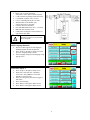
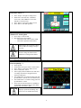
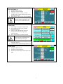
Active Harmonic Filter
Quick Start Unit Software Setup
TCI, LLC
W132 N10611 Grant Drive
Germantown, Wisconsin 53022
Phone: 414-357-4480
Fax: 414-357-4484
Helpline: 800-TCI-8282
Web Site: http://www.transcoil.com
© TCI, LLC
No part of this publication may be reproduced, stored in a retrieval system, or transmitted in
any form or by any means, mechanical, electronic, photocopying, recording, or otherwise,
without the prior written permission of TCI, LLC. The information in this manual is subject
to change without notice. Every precaution has been taken in the preparation of this manual.
TCI, LLC assumes no responsibility for errors or omissions. Neither is any liability assumed
for damages resulting from the use of the information contained in this publication.
2
Warning
!
Warning
!
Warning
!
Warning
Be sure to read, understand, and follow all safety instructions.
Only qualified electricians should carry out all electrical installation and maintenance work on the
HarmonicGuard Active Filter (HGA).
All wiring must be in accordance with the National Electrical Code (NEC) and/or any other codes that
apply to the installation site.
Disconnect all power before working on the equipment.
Do not attempt any work on a powered Active Harmonic Filter.
Warning
The HGA, drive, motor, and other connected equipment must be properly grounded.
Warning
The HGA may receive power from two or more sources.
Three-phase power is connected to the main input terminals of the HGA.
All of these sources of power must be disconnected before working on the HGA.
Warning
After switching off the power, always allow 5 minutes for the capacitors in the HGA and in the drive
to discharge before working on the HGA, the drive, the motor, or the connecting wiring. It is good
practice to check with a voltmeter to make sure that all sources of power have been disconnected and
that all capacitors have discharged before beginning work.
NOTE: Full User Manual
• For the full user manual and other supporting
documentation please go to:
http://www.transcoil.com
http://www.transcoil.com
3
1) Verify unit external connections
• Phase A, B, C power connection,
with positive A-B-C phase rotation expected
• CT H1 Terminal is pointing toward the source
• CT feedback on phases A & C to TB-1
• Leave CT shorting bars in place on TB-1
• With the HGA circuit breaker open,
energize the source to the HGA
• Close the HGA circuit breaker
• Fans and HMI should come on in < 5 seconds
• HMI will start on Home screen
• Load(s) have an integral 5% line reactance or
equivalent dc bus choke
Warning
!
Hazardous voltages are present when
unit is energized
NOTE: Language Selection
• The active filter supports several languages
including English, French and Spanish
• Press “Setup” to navigate to Setup screen and
press the “Language Setup” button.
• Select language setting from the language setup
pop-up screen.
2) Converter check - 1
• Press “Setup” to navigate to Setup screen
• Ensure that “Auto Start En,” “Harmonic
Correct En,” and “PWR Fact Correct En”
buttons are off (blue color)
• If they are ON (green) press them to toggle to
OFF (blue)
• Press “Save Settings”
• Press “Status” to navigate to Status screen
• Press “Home” to navigate to Home screen
4
NOTE: Built In Sensor Wiring Error Detection
• The active filter has an automatic sensor wiring
error detection algorithm built in to the
controls.
• If a sensor wiring error is detected please
reference the Sensor Error Auto Detection
section of the full user manual available at
www.transcoil.com.
3) Home screen check
• Compare “Freq” to expected line frequency
• Compare “Supply Voltage” to expected
line voltage
• “Current” expected to be zero because unit is
not running and CT inputs are shorted
• If status indicates a Fault, press “Stop” button
to reset condition
4) Status screen check
• Press “Status” to navigate to Status screen
• Compare “Volts” to expected line voltage
• Compare “Freq” to expected line frequency
• “Current” expected to be zero if unit is not
running and CT inputs are shorted
5) Phase rotation check
• Press “Phase to Neutral Voltage Plot”
• Check that the current peaks follow the
following sequence from left to right: Phase A
(green), Phase B (blue), Phase C (red)
• Equipment is phase rotation sensitive, if phase
rotation is incorrect, power down unit and
rewire to adjust phase rotation by swapping
two incoming phase connections
Warning Improper operation will occur when
input voltage phase rotation is
incorrect.
5
6) Converter check – 2
•
•
•
•
Press “Setup” to navigate to Setup screen
Ensure that “Auto Start En,” “Harmonic
Correct En,” and “PWR Fact Correct En”
buttons are off (blue color)
Press “Status” to navigate to Status screen
Press “Run” to start unit operation
7) Remove CT shorting bars
• Press “Stop” to turn off unit
• Disconnect power from cabinet
o Turn off the built in door breaker AND
o Turn off the upstream feeder breaker
Warning Lethal voltages may be present. Wait 5
minutes for DC bus voltage to drop to
safe levels.
Warning
•
Check for voltage in cabinet with a
DMM before working inside cabinet.
Open the cabinet door and remove shorting bars
from CTs connected to TB-1
8) Current polarity - 1
• Power up unit
• From Home screen press “Run” to turn on unit
• Press “Status” to navigate to Status screen
• Select “Vline/Iline” screen
• Note: Lightly loaded conditions (less than 20%
CT rating) will not have enough current to
show up on Iline plot
• Check that Phase A to Neutral voltage peak lines
up with Phase A current (use zoom if necessary)
• Check that Phase C to Neutral voltage peak lines
up with Phase C current
• Power system down and check CT installation
location and orientation if Phase A plots differ
significantly from Phase C plots
Warning
Improper operation and damage may
occur if CTs are installed incorrectly.
6
9) Current Polarity – 2
• Navigate to Status screen
• Navigate to Line/Load status
• Verify that “Volts,” “Current,” “Power,”
“I THD," and “V THD” match expected values
for the power system
• If they do not, verify CTs are correctly installed
Warning
Improper operation and damage may
occur if CTs are installed incorrectly.
10) Final setup
• Press “Setup” to navigate to Setup screen
• Press “Harmonic Correct En” to enable
harmonic correction
• If unit is sized with sufficient capacity to
provide power factor correction, press
“PF Correct En”
• Press “Auto Start En” to enable Autostart
Warning
When Auto Start is enabled unit may
operate without operator input.
•
•
Press “Save Settings” to save settings
and restart converter
Let the unit come on automatically (about 30 s)
11) Final check
• Navigate to Status screen
• Navigate to Line/Load status
• Note the corrected voltage, current, power and
THD
7
TCI, LLC
W132 N10611
Germantown, Wisconsin 53022
Phone: 414-357-4480
Fax: 414-357-4484
Helpline: 800-TCI-8282
Web Site: http://www.transcoil.com
©2013 TCI, LLC
Publication No: 28666
Effective: 10/29/13
Printed in USA
8
Revision: A