1
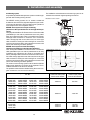
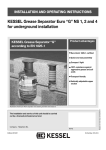
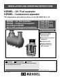
INSTALLATION AND OPERATING INSTRUCTIONS
KESSEL – Oil / Fuel separator
KESSEL – Coalescence separator
PE Separators according to Euro-norm EN 858 NS 3-15
KESSEL – Oil / Fuel separator
KESSEL – Coalescence separator
According to EN 858
NG 3-15 for underground installation
99 403 - 99 615
(.10/.15/.30/.80) (B/D)
99 503 - 99 715
(.10/.15/.30/.80) (B/D)
99 703 (.04/.10) (B/D)
99706.10 (B/D
Product advantages
Easy on-site mobility
without the need for
heavy machinery
Simple and quick installation
and hook up
Recyclable material
Installation
Commissioning
Instruction
The installation and service of this unit should be carried out by
a licensed professional servicer
Name
Edition 2009/11
Date
Town
Company - Telephone No.
Subject to technical amendment
Seamless body due to
monolith construction –
100% watertight
ID number 010-619
1. Safety Instructions
Personnel used for installation, assembly, operation, maintenance and repair must have the corresponding qualifications for such work. Areas of responsibility and the supervision of personnel
must be clearly specified by the operator.
The operating safety of the system supplied is only ensured in the event of proper use. The limit
values specified in the technical data must not be exceeded under any circumstances.
Accident prevention regulations and the applicable standards and directives must be observed
at all times during installation, assembly, operation, maintenance and repair of the system!
These include:
• Accident prevention regulations
- Construction work, BGV C22
- Waste water systems, GUV-V C5
• Safety regulations for work in enclosed areas of waste water systems, GUV-R 126
• Handling of biological materials in waste water systems, GUV-R 145
• Directives for work in tanks and restricted areas, BGR 117
• Standards
- Construction pits and ditches - Embankments, shoring, working area widths, DIN 4124
- Laying and testing of waste water pipes and channels, DIN EN 1610
• Work aids for safety and health protection in waste water systems.
ACCESS:
NO SMOKING! Smoking is strictly prohibited near or around the separator at all times !
All sources of ignition or sparks are prohibited near or around the separator at all times !
SLIPPERY WHEN WET! Take caution when standing / walking near the separator. During disposal, cleaning and maintenance the surrounding area can become extremely slippery due to
spilled oil / fuel.
• Dangers from gases and vapours such as the danger of suffocation,
poisoning or explosion
• Danger of falling
• Danger of drowning
• Fecal pollution in waste water containing faeces
• High physical and psychic stresses of work in deep, restricted or dark areas
• and others
Failure to observe these operating instructions may result in substantial material damage, physical injuries or fatal accidents.
The system constitutes one component of an overall system. The operating instructions of the
overall system and the individual components must therefore also be observed. During all assembly, maintenance, inspection and repair to any of the components, the overall system must
be shut down and secured against restarting.
Conversion or modifications to the system must only be made after consultation with the manufacturer. Original spare parts and accessories approved by the manufacturer must be used in
order to ensure safety. The use of other parts may invalidate liability for the resulting consequences.
2
Table of Contents
1. Safety Instructions
2. General
3. Technical Data
4. Transport, Storage
5. Installation and assembly
6. Operation
7. Disposal
8. Maintenance
2.1
2.2
3.1
3.2
3.3
3.4
3.5
3.6
4.1
4.3
5.1
5.2
5.3
5.4
5.5
5.6
5.7
6.1
6.2
6.3
................................................................................. Page
Application................................................................ Page
Separator description .............................................. Page
2
4
4
Installation example Oil-/Fuel Separator ...........................
Dimensioned drawings Oil-/Fuel Separator ......................
Installation example Coalescence Separator .................
Dimensioned drawings Coalescence Separator.................
Drawing Coalescence Separator Inspection Chamber LW 1000 .....
Dimensioned drawings Coalescence Separator
Inspection Chamber LW 1000...............................................
Page
Page
Page
Page
Page
6
6
7
7
8
Transport .................................................................. Page
Storage..................................................................... Page
Assembly requirements............................................
Filling Material ..........................................................
Excavation pit...........................................................
Tryouts before assembly .........................................
Assembly..................................................................
Alarm unit .................................................................
Oil and Sludge extraction .........................................
Page
Page
Page
Page
Page
Page
Page
9
9
Page
8
10
11
11
11
11
13
14
Making the plant ready for operation........................ Page 16
Commissioning / Instruction ..................................... Page 16
Important info ........................................................... Page 16
.............................................................................................. Page 16
.............................................................................................. Page 18
9. Accessories / Replacement parts .............................................................................................. Page 20
10. Warranty
.............................................................................................. Page 21
12. Important contacts / info
.............................................................................................. Page 23
11. Separator characteristics
.............................................................................................. Page 22
3
Dear Customer,
Before the KESSEL Oil / Fuel or Coalescence separator is installed and placed in operation please carefully read and
follow all of the instructions contained in this Installation, Maintenance and User's Manual.
Upon delivery of the KESSEL separator please thoroughly inspect the separator to make sure that it has not been
damaged during shipping. In case damage has occurred to the separator, please follow the instructions listed in the,
Guarantee section of this user's manual.
2. General
2. General
2.1 Area of application
The separators are intended for use under specified conditions, see the Chapter “Installation and assembly”, for installation underground or below the foundation slab in well-ventilated areas.
2.1.1 Oil-fuel separators to Separator Class II
The separators can be used:
a) for the treatment of rainwater contaminated with light
fluids from surfaced areas, e.g. filling stations, oil storage
and handling areas, parking areas and streets in water protection areas
b) as a retaining system for light fluids from systems and
areas where light fluids are handled, e.g. filling stations, oil
storage and handling areas
c) for preliminary separation of light fluids from waste water
before further treatment in subsequent internal waste
water treatment plants.
In cases a) and b), the discharged water from the separators
is intended to be fed back into the public drainage system.
If the discharged water is to be returned into waters, this is
only possible in individual cases following clarification with
the local water authority.
In the treatment of dirty water contaminated with light fluids
(commercial waste water) or waste water from the application areas of Appendix 49 of the waste water regulations, the
observation of a limit value for hydrocarbons of 20 mg/l cannot be considered to have been observed.
Separators for light fluids with coalescence device can be
used:
a) for the treatment of rainwater contaminated with light
fluids from surfaced areas, e.g. filling stations, oil storage
and handling areas, parking areas and streets in water protection areas,
b) as a retaining system for light fluids for the safety of systems and areas where light fluids are handled, e.g. filling
stations, oil storage and handling areas,
c) for the treatment of dirty water contaminated with light
fluids (commercial waste water) produced taking into account the operating conditions of industrial processes,
the cleaning of parts contaminated with oil and the cleaning of floor areas contaminated with oil (except workshop
floors),
d) for the treatment of waste water produced taking into account the operating conditions of automatic vehicle cleaning (partial flow: outlet from the closed circuit into the
drainage system), manual cleaning (vehicle washing, engine washing, underbody washing, chassis cleaning in
washing bays, self-service or commercial washing bays except for the cleaning of workshop floors contaminated
with oil) and for the drainage of areas used for the receipt,
storage, drying, dismantling and crushing of old vehicles,
e) for preliminary separation of light fluids from waste water
before further treatment in subsequent internal waste
water treatment plants.
2.1.2 Oil-fuel separators to Separator Class I
4
3. Installation
2.3 Functional description
햲
햸
햹
햶
햵
햴
햷
햺
햻
햳
In cases a) to d), the discharged water from the separators is
intended to be fed back into the public drainage system.
If the discharged water is to be returned into waters, this is
only possible in individual cases following clarification with
the local water authority.
Separators used in case d) are used in systems for the restriction of hydrocarbons in waste water containing mineral
oil in the sense of Part E Paragraph 2 of Appendix 49 of the
waste water regulations.
The level of hydrocarbons required by regulations in cases
c) and d) of 20 mg/l is considered to have been observed.
2.2 System description
The illustration shows a fuel separator cistern installed in
the ground of Class A/B.
Outlet point without stench trap
Light fluid separator
Inlet with stench trap
Outlet with self-actuating closure
Guide tube
Float
Attachment piece
Cover
Sample removal shaft
Backwater valve
5
The separators separate light fluids and sludge out of the
waste water by means of gravity. Light fluids refers to fluids
of mineral origin with a density of ≤ 0.95 g/cm3, which are insoluble or only slightly soluble in water, and which are nonsaponifiable. These do not include stable emulsions, fats
and oils of vegetable or animal origin. Light fluids float up in
the separation chamber and collect at the surface. Sludges,
which are heavier than water, sink to the bottom and form a
sludge layer.
Coalescence separators, like oil-fuel separators, work on the
principle of gravity. To increase the separation performance,
the tank also contains a coalescence insert. This cylindrical
insert has two functions. Firstly, it affects the flow in the separator, and secondly it “filters” all the waste water through
the coalescence material.
When waste water containing oil flows through this filter fabric, very fine oil droplets that can no longer be separated out
by gravity collect on the coalescence material, and combine
to form large oil droplets. When these reach a sufficient size
to create buoyancy, they detach themselves from the filter
material and rise to the surface.
Light fluid separators are equipped as standard with a selfactuating closure.
When the maximum oil storage volume is exceeded, this device closes the outlet into the drainage system. This prevents
the escape of light fluids into the drainage system. This safety device consists of a guide tube full of water, which houses a float.
The float is carefully designed with regard to its weight, so
that it floats in water, and sinks in light fluid (up to a density
of 0.95 g/cm3). When the maximum oil storage quantity is reached, oil flows through the lateral openings into the float
guide tube. The float then sinks, reliably shutting off the outlet of the separator.
The self-actuating closure of a separator is an “emergency
closure valve”. When actuated in an emergency, the separator must be taken out of service and maintained.
3. Installation
3.1 Installation example: KESSEL Oil / Fuel Separator
Illustration shows KESSEL-oil-/fuel separator class II with cover class B and sampling chamber.
3.2 Dimensioned drawing
DN 150: T-TEÜ = 155 mm
DN 200: T-TEÜ = 180 mm
T-TEÜ = Height above ground
Class D: 700 mm ≤ TEÜ ≤ 1.500 mm
Class A/B: 700 mm ≤ TEÜ ≤ 1.800 mm
NS
Sludge trap
(l)
Total
Oil storage Overstand Weight
(mm)
volume (l)
(l)
(Kg)
1) Comparable total sludge trap volume according to dimensioning of DIN EN 858
2) Eccentric reduction of inlet/outlet to DN 150 possible on site, fitted through DN 150 sample removal shaft
6
Cover
class
Art No.
3. Installation
3.3 Installation example: KESSEL Coalescence separator
Illustration shows KESSEL-coalescence separator class I with cover class B and sampling chamber.
3.4 Dimensioned drawing
DN 150: T-TEÜ = 155 mm
DN 200: T-TEÜ = 180 mm
T-TEÜ = Height above ground
Klasse D: 700 mm ≤ TEÜ ≤ 1.500 mm
Klasse A/B: 700 mm ≤ TEÜ ≤ 1.800 mm
NS
Total
Oil storage Overstand Weight
(mm)
volume (l)
(l)
(Kg)
Sludge trap
(l)
1) Comparable total sludge trap volume according to dimensioning of DIN EN 858
2) Eccentric reduction of inlet/outlet to DN 150 possible on site, fitted through DN 150 sample removal shaft
7
Cover
class
Art No.
3. Installation
3.5 Illustration: KESSEL coalescence separator shaft
LW 1000, NS 3
NS
Sludge trap
(l)
3
3
3
3
800
800
1600
1600
Total
Oil storage Overstand Weight
(mm)
volume (l)
(l)
(Kg)
Ø
100
100
100
100
1100 Ø
1100 Ø
1100 Ø
1100 Ø
3.6 Dimension drawing of KESSEL coalescence
separator shaft LW 1000, NS 3
545 995 1105 1055
545 995 1105 1055
545 995 1605 1555
545 995 1605 1555
790
790
1390
1390
200
200
200
200
110
110
110
110
175
205
190
220
Cover
class
Art No.
B
D
B
D
99703.04B
99703.04D
99703.10B
99703.10D
3.7 Dimensioned Drawing KESSEL-coalescence separator LW 1000, NS 6 (with upstream sludge trap)
NS
6
6
Sludge trap
(l)
1000
1000
Ø
150
150
1100 Ø
1100 Ø
560 1010 1090 1020
560 1010 1090 1020
Total
Oil storage Overstand Weight
(mm)
volume (l)
(l)
(Kg)
1580
1580
200
200
110
110
8
305
338
Cover
class
B
D
Art No.
99706.10B
99706.10D
4. Transport and Storage
Transportation of the KESSEL separator should be handled
only by a transporter who has the proper knowledge, equipment
and employees to handle such a product. During transport the
separator must be firmly fixed into position and must not be allowed to move or shift in place. It also must be protected from
other objects coming in contact with the separator during transport.
If and when the separator is lifted it is important to follow the following correct procedures: The separator is not to be lifted with
the use of steel cables or chains. Proper equipment are heavy
duty cloth or hemp straps designed to handle the corresponding
loads. The separator should be lifted by placing the proper
straps beneath the inlet and outlet of the separator as seen in
the illustration. Do not lift the separator by the small holes between the two manholes covers as illustrated on this page. In instances where a forklift is used, secure the separator to the forklift with appropriate cloth / hemp securing straps.
Storage
In cases where the separator needs to be temporarily stored before installation, it is important that the separator is placed on
firm level ground and in an area where it is protected from coming in contact with other objects. Storing the separator outdoors will not cause any problems.
9
5. Installation and assembly
During interim storage of the separator and up to the end
of the installation work, suitable safety measures must be
taken on the construction site to avoid accidents and damage to the light fluid separator.
The Chapter Safety Instructions must be observed!
edge of the lowest connected outlet. The necessary projection
depends on the nominal size of the separator (see Chapter on
Technical Data).
If this excess height cannot be maintained, a warning device for
light fluids must be installed.
5.1 Installation requirements
The installation must be carried only by companies who have
the necessary specialist experience, suitable equipment and
adequately trained personnel for the task.
The soil characteristics must be investigated for technical construction suitability (soil classification for technical construction
purposes, DIN 18196). The maximum ground water level likely
to occur must also be established. The ground water level must
not exceed the level of the outlet. Adequate drainage of seepage water is also essential in the case of soils impermeable to
water. The types of stresses occurring, such as maximum traffic loads and installation depth, must also be clarified.
Drainage area
Surface level covers
Elevated area
The separators for ground installation should be installed outside the building, as near as possible to the outlets. If necessary, the connection pipes of the inlets to the separator should
be laid with heat insulation, or heated. The required frost-free
installation depth is achieved by the use of telescopic attachment pieces, which also allows easy adjustment to feed and outlet pipes (drainage system). The covers for the load classes A
/ B and D are not bolted and comply with EN 124.
Separator system ready for use
Separator systems must be installed close to the point of origin of the light fluids. They must be easily accessible for cleaning and maintenance purposes.
Light fluid separators must be protected against reverse flow
from the drainage system.
KESSEL recommend the following protective precautions:
Illustration 1
The use of locked or ventilated covers is prohibited.
Outlet point
Separator
Reverse flow protection
Pump or lifting systems must not be installed in the supply line
in front of the separator. If these are necessary, they must be installed after the separator.
Inside a building
Projection
available
No projection
Reverse flow closure
For the reliable operation of the system, KESSEL recommends
the installation of a projection, and also a warning system. The
necessary fitting requirements must be provided before filling
of the construction pit.
Outside a building
Projection
available
No projection
Reverse flow closure
Inside a building
Outside a building
Separator systems must be installed so that the upper edge of
the covers is sufficiently high in comparison to the made level
of the surfaces to be drained (see Figure 1).
The fluid level in the separator is always higher than the water
level in the drainage system due to the difference in density between light fluid and water.
The definitive level is the highest possible standing rainwater
height, when dirty water and rainwater are channelled together.
If only dirty water is being fed in, the definitive level is the upper
10
Reverse flow closure
Lifting system
5. Installation and assembly
5.2 Filling material
The separator must only be installed in non-cohesive or low-cohesive soils (Group G1 to G2 to ATV-DVWU - A127).
Substrate:
Round-particle gravel
(max. particle size 8/16) to DIN 4226-1
Tank bed:
Sand
Tank jacketing: Round-particle gravel
(max. particle size 8/16) to DIN 4226-1
Area outside tank jacketing:
Material with suitable properties
Covering layer: Humus or similar
5.3 Construction pit
The foundation must be horizontal and level in order to be able
to set up the system over the full surface, and must also afford
adequate load-bearing capability. The substrate consists of
compacted round-particle gravel (max. particle size 8/16, minimum depth 30 cm, Dpr=95%), covered by 3 - 10 cm of compacted sand. The spacing between the construction pit wall
and the tank must be at least 70 cm. The embankments must
be constructed to DIN 4124. The depth of the construction pit
should be such that the limits of the earth covering are not exceeded.
MIN ≤ TEÜ ≤ MAX (see dimension drawing in the Chapter on
Technical Data).
Root penetration
In case of installation in the vicinity of trees or shrubbery, penetration by roots must be reliably prevented.
Installation on a sloping site
In case of installation of the separator on a sloping site, care
must be taken to ensure that the laterally-acting soil pressure
of unsecured soil is absorbed by a suitably dimensioned supporting wall.
Frost-free depth for all-year-round use
Always take care to observe the locally established frost-free
depth when installing the separator. In order to ensure the
smooth operation even in winter, the inlet and outlet pipes must
also be laid at a frost-free depth during installation.
5.4 Tests before installation
Immediately before installation of the tank in the construction
pit, the responsible specialist of the company carrying out the
installation must test and certify the following:
- the integrity of the tank wall;
- the proper condition of the construction pit, in particular with
regard to the dimensions and substrate bedding;
- the particle size of the filling material.
11
햶
햷
≤ 20cm
햵
≤ 30cm
≤ 30cm
≤ 30cm
≤ 30cm
≥ 50cm
햴
≥ 50cm
yyyyyyyyyy
b nach
DIN 4124
햲
≥ 70cm
햳
햲 Subbase: round-grain gravel (max.
graining 8/16) according to DIN
4226-1 compacted with Dpr=95%
햳 Tank bed: compacted sand
햴 Tank
햵 Tank encasing: round-grain gravel
(max. graining 8/16) according to
≤ 30cm
≤ 30cm
≤ 30cm
≤ 30cm
≤ 30cm
3-10cm
≥ 30cm
≥ 70cm
DIN 4226-1 compacted with
Dpr=95%
햶 Area outside tank encasing: material of suitable
consistence
햷 Top layer: topsoil, road surface,
concrete or similar
5.5 Installation
The float and coalescence insert, if fitted, remain in the tank during installation.
Insertion
The tanks must be placed carefully in the construction pit with
the aid of suitable lifting equipment and positioned on the substrate bedding (see also the Chapter “Transport”).
Filling of the tank and the backfilling construction pit
In order to avoid deformation of the tank, the filling of the tank
with water and the construction pit should take place in parallel.
The tank jacketing should be applied to a width of at least 50
cm. The backfilling around the tank should take place in 30 cm
incremental layers. Each layer should be compacted with light
compaction devices (min. Dpr=95%). Damage to the tank wall
and displacement of the tank during and after installation must
be avoided. The self-actuating closure keeps the system closed during the complete filling process.
Connection of the tank
Any transport safety devices fitted must be removed. Note: the
pipe connection fittings must be protected against damage in
order to ensure the permanent integrity of the system. To make
connection easier, the pipe connection fittings should be adequately greased.
The transition from downpipes to horizontal pipes must be
made using two 45° elbows separated by an intermediate pipe
at least 250 mm long. A calming section must be installed in
front of the separator system, which must be at least 10x as
long as the nominal width of the feed pipe.
5. Installation and assembly
When the construction pit has been filled and compacted to
the lower edge of the feed and outlet connections, the feed
and outlet pipes are laid frost-free and connected.
Instructions for the warning system: Lay the connection
cable or empty pipe during the earthworks.
Insert the lip seal DN 600 in the groove in the dome
Telescopic attachment
Connection of the sample removal shaft.
Sample removal devices must be installed in the direction
of flow immediately after the separator. The sample removal
device of the separator system must be freely accessible
and positioned so that only waste water is removed which
has passed through the separator.
Connection of the warning system empty pipe,
if applicable
The connecting section between the separator and control
unit must be kept as short as possible.
Unnecessary changes of direction, in particular those with
angles above 45°, should be avoided.
The empty pipe for the cable should have a continual slope
down to the separator.
The formation of condensation within the empty pipe can be
minimised by an airtight closure of the empty pipe on the
side of the control unit. A cable pull-through wire can also
be laid for subsequent cable laying.
7
6
5
3
1
(1) KESSEL light fluid separator
(2) Layer thickness sensor
(3) Reverse flow sensor
(4) Control unit
(5) Housing for wall installation
4
8
2
(6) Watertight cable connection
(7) Attachment set
(8) Empty pipe closure
Lip seal DN
600
Minimum insertion
depth 100 mm
Tank dome
and apply grease
Insert the telescopic KESSEL upper section into the
opening of the separator and adjust to the required position. With the aid of the clamping ring, the upper section can now be fixed in the required position (aligned
with the upper ground level). The fine adjustment to the
final height is then made with the aid of the setscrews.
Slopes can easily be compensated for by the fully heightadjustable and inclining upper section. The upper section
must be adequately supported from underneath and vibrated in using a flat-bed vibrator and a steel plate laid
on the upper section.
For greater installation depths, the special KESSEL intermediate piece (Art. no. 917402), height 400 mm, intended for this purpose should be used.
remaining filling
For installation in areas of heavy vehicle traffic (cover
class D), a reinforced concrete slab must be provided as
the upper layer. A corresponding formwork and reinforcement plan is available from KESSEL.
12
5. Installation and assembly
5.6 Warning system
As specified by DIN EN 858, separator systems must be equipped with self-actuating warning devices.
The KESSEL warning systems Art. no. 917801, 917802 and
917806 are alarm devices for light fluid separators (fuel, coalescence and oil separators). They are approved for operation in
areas subject to the risk of explosion, Zone 0.
KESSEL alarm system for oil layer monitoring
(detection of the layer thickness in oil and light fluid separators)
Oil layer probe suitable for Ex-Zone 0 with 5 m connection cable
(extendible up to max. 200 m), attachment set for easy installation and maintenance (the probe is accessible from above),
watertight cable connector for extension of the connection
cable, through-pipe with screw closure and two screw-type
cable connectors, housing for wall mounting IP 65, control unit
with visual and acoustic alarm with potential-free contact, with
sensor self-monitoring and alarm repetition.
KESSEL alarm system for limit value display
(detection of backing up in the light fluid separator)
Limit value probe suitable for Ex-Zone 0 with 5 m connection
cable (extendible up to max. 200 m), attachment set for easy
installation and maintenance (the probe is accessible from
above), watertight cable connector for extension of the connection cable, through-pipe with screw closure and two screw-type
cable connectors, housing for wall mounting IP 65, control unit
with visual and acoustic alarm with potential-free contact, with
sensor self-monitoring and alarm repetition.
The sensors of the warning system must be fitted at different
height levels, depending on the size of the separator. The installation dimensions are shown in the table.
The specified values must be checked during the course of regular maintenance, and corrected if necessary.
99403.10B
99403.10D
99610.15B
99610.15D
99606.30B
99606.30D
99610.30B
99610.30D
99606.80B
99606.80D
99610.80B
99610.80D
99615.80B
99615.80D
99703.04B
99703.04D
99703.10B
99703.10D
Light fluid separator Art. No.
Art. No.
99403.10BEX
99403.10DEX
99610.15BEX
99610.15DEX
99606.30BEX
99606.30DEX
99610.30BEX
99610.30DEX
99606.80BEX
99606.80DEX
99610.80BEX
99610.80DEX
99615.80BEX
99615.80DEX
99503.10B
99503.10D
99710.15B
99710.15D
99706.30B
99706.30D
99710.30B
99710.30D
99706.80B
99706.80D
99710.80B
99710.80D
99715.80B
99715.80D
13
The installation and maintenance of the warning system is described in the enclosed original operating instructions.
Illustration of the cistern
100 mm
100 mm
A
B
(*)
30°
30°
45°
(*)Illustration of the oil
layer probe
99503.10BEX
99503.10DEX
99710.15BEX
99710.15DEX
99706.30BEX
99706.30DEX
99710.30BEX
99710.30DEX
99706.80BEX
99706.80DEX
99710.80BEX
99710.80DEX
99715.80BEX
99715.80DEX
Old probe
New probe
113 mm
Oil layer
Alarm level
Water
Distance A
of the limit value probe
from the tank bottom
Distance B
of the oil layer probe
from the tank bottom
1820 mm
1335 mm
1230 mm
1230 mm
1730 mm
1730 mm
764 mm
764 mm
1264 mm
1264 mm
1340 mm
835 mm
5. Installation and assembly
Note: The holes for the attachment set must be drilled only
at the specified positions. The holes must be made using a
3.5 mm diameter drill. The original attachment screws must
be used in the attachment, without plugs.
The positions of the holes should be adjusted accordingly if
the seal might be damaged by the drill. Under no circumstances must the cone of the rotation tank be damaged or
drilled through!
The extension of the cable to max. 200 m is only possible
using original parts (cable and cable connectors).
Information can be obtained from the KESSEL Customer
Service Department under telephone no. 0 18 05-27 82 82.
The use of any parts other than KESSEL original parts will
invalidate the ATEX approval, the construction type approval and any guarantee claims against KESSEL.
When drawing in the cable into the empty pipe to the control unit, the cable screw connections on the empty pipe closure must be tightened firmly. The union nut must then be
fixed to the end of the pipe.
This is beneficial particularly for businesses with a high level of
sludge. The complete separator can of course also be emptied
by the sludge extraction device.
If both devices are used for disposal, it must be ensured that
the oil is disposed of first, followed by the sludge.
The retaining device is attached at the inlet, using the pipe
clamp as shown in the drawing.
Fit the oil extraction to the retaining device, set to the required
height x (see Table) and fix in position.
Stub connection
Sludge extraction
Oil extraction
Retaining device
Sludge
1
2
Inner side
3
5
(1) Cables to the probes
(2) Cable screw-fittings
(3) Union nut
(4) Through-seal
6
4
7
Outer side
(5) Empty pipe closure
(6) Through-pipe
(7) Empty pipe
5.7 Oil and sludge extraction
(for shaft LW 1000 on request only)
For normal disposal, the hose from the suction vehicle is held
in the light fluid separator and the complete contents pumped
out.
The volume of light fluid is however significantly less than the
total volume of the separator. Assistance is provided in this case
by the oil extraction device.
For disposal of the light fluid, the suction hose is connected to
the oil extraction device. The suction vehicle can then remove
only the volume corresponding to the maximum light fluid quantity.
This means a significant reduction of the disposal quantity,
which together saves both time and disposal costs, and causes less wear to the separator components. In the same way
as the oil extraction device, the disposal quantity can also be
significantly reduced by the sludge extraction device.
Fit the sludge extraction to the retaining device, feed to the bottom and then fix in position.
Fit the stub connections to the attachment as shown in the drawing using the stainless steel screws provided.
14
5. Installation and assembly
The holes must be made using a 3.5 mm diameter drill. Use the
stub connection as a drilling template.
Fit the knuckle coupling to the end of the hose and fix with a
hose clamp.
Hook the hose with the knuckle coupling upwards in the stub
connection, lead to the extraction device and adjust to the required length.
Connect the hose and extraction device and fix using a hose
clamp.
When the cover is closed, it must not be in contact with the
knuckle coupling.
Light fluid separator Art. No.
99403.10B
99403.10D
99610.15B
99610.15D
99606.30B
99606.30D
99610.30B
99610.30D
99606.80B
99606.80D
99610.80B
99610.80D
99615.80B
99615.80D
99703.04B
99703.04D
99703.10B
99703.10D
99403.10BEX
99403.10DEX
99610.15BEX
99610.15DEX
99606.30BEX
99606.30DEX
99610.30BEX
99610.30DEX
99606.80BEX
99606.80DEX
99610.80BEX
99610.80DEX
99615.80BEX
99615.80DEX
99503.10B
99503.10D
99710.15B
99710.15D
99706.30B
99706.30D
99710.30B
99710.30D
99706.80B
99706.80D
99710.80B
99710.80D
99715.80B
99715.80D
15
Distance X of the oil extraction from the tank bottom
99503.10BEX
99503.10DEX
99710.15BEX
99710.15DEX
99706.30BEX
99706.30DEX
99710.30BEX
99710.30DEX
99706.80BEX
99706.80DEX
99710.80BEX
99710.80DEX
99715.80BEX
99715.80DEX
950 mm
1450 mm
On request
6. Commissioning
The chapter "Safety instructions" must be heeded.
6.1 Setting up for operation
Before the separator is put into operation, please make sure
that:
the separator is clean and the interior is free from any objects which may have been placed inside during shipping
or installation.
the separator is completely filled with clean cold water.
Completely filling the separator is complete when water
begins to drain from the outlet.
6.2 Initial Instructions
Placing the separator into full operation is normally handled
by a licensed tradesman although upon request can be handled by a KESSEL representative.
The following personnel should be on hand when the initial
instructions for placing the separator into operation are given:
Building facilities manager
Building maintenance workers
Contracted plumber / tradesman
Contracted disposal company
What to do:
Check to make sure the separator is completely watertight. Check to make sure that during transport and
installation that no damage to the separator was
caused. Check to make sure all connections to the
separator (inlet, outlet, refill, rinse pipes etc.) are in
perfect working order.
Representative should discuss all necessary information regarding the disposal.
Representative should take the customer step by step
through all stages of a separator disposal.
After the separator has been emptied (disposed) all
necessary paperwork and documentation should be
handed over to the customer.
The separator should be returned to service by filling
the separator with fresh, cold water.
6.4 Hand-over of installation and userʼs manual.
6.5 Completion of the commissioning report.
After commissioning has been completed the separator
should be placed into normal operation mode.
6.3 Commissioning report (see attachment)
7. Disposal
Disposal intervals:
The fuel / oil collected in the separator should be collected /
disposed when the level has reached 80% of the maximum
storage capacity. Disposal of collected sludge in the base of
the separator should be collected / disposed when the level
has reached 50% of the maximum sludge storage capacity.
Important: Timely disposal of the separator is mandatory to
insure proper function and operation of the separator.
A licensed disposal company should be contracted to handle disposal of the separator. Disposal should take place when
little or no wastewater is entering the separator.
Emptying intervals:
The light fluid retained in the separator must be removed at the
latest when the quantity of separated light fluid reaches 80% of
the maximum storage quantity, or the level is below the retained volume. For separators simultaneously or exclusively used
for the drainage of systems or areas where light fluids are handled (e.g. fuelling areas), the retained volume required under
state regulations must also be provided. The separated light
fluid must also be removed at levels below this retained volume if the quantity of separated light fluids has not yet reached
80 % of the maximum storage quantity.
The disposal of the sludge contained in the sludge trap must
be removed at the latest when the separated sludge quantity
reaches half of the sludge trap volume.
Note: Light fluids and sludge must be removed as specified
above in order to ensure the correct operation of the system.
For this reason, a disposal contract should be concluded with
a specialist disposal company. The disposal work should be
carried out if possible when the system is not in operation.
Expected disposal volumes in accordance with the filling level
can be estimated by means of the following table.
The figures contained in the table are approximate figures only
for the purposes of estimating quantities when contracting a
specialist disposal company.
16
7. Disposal
Oil-/fuel Separator
Art.-Nr.:
99403.10B 99403.10BEX 99503.10B 99503.10BEX
99403.10D 99403.10DEX 99503.10D 99503.10DEX
99610.15B 99610.15BEX 99710.15B 99710.15BEX
99610.15D 99610.15DEX 99710.15D 99710.15DEX
99606.30B
99606.30D
99610.30B
99610.30D
99606.80B
99606.80D
99610.80B
99610.80D
99615.80B
99615.80D
99703.04B
99703.04D
99606.30BEX
99606.30DEX
99610.30BEX
99610.30DEX
99606.80BEX
99606.80DEX
99610.80BEX
99610.80DEX
99615.80BEX
99615.80DEX
99706.30B
99706.30D
99710.30B
99710.30D
99706.80B
99706.80D
99710.80B
99710.80D
99715.80B
99715.80D
99706.30BEX
99706.30DEX
99710.30BEX
99710.30DEX
99706.80BEX
99706.80DEX
99710.80BEX
99710.80DEX
99715.80BEX
99715.80DEX
1)
Filling level
in %
50
40
30
20
10
50
40
30
20
10
50
40
30
20
10
50
40
30
20
10
Sludge
Measured
layer thickness
in mm
650
530
430
330
210
650
550
450
340
220
1100
930
760
580
370
1100
910
740
560
350
Disposal
volume
in litres
1000
800
600
400
200
1500
1200
900
600
300
3000
2400
1800
1200
600
4000
3200
2400
1600
800
2)
Filling level
in %
100
80
60
40
20
100
80
60
40
20
100
80
60
40
20
100
80
60
40
20
Oil-/Fuel
Measured
layer thickness
in mm
131
105
79
52
26
131
105
79
52
26
138
110
83
55
28
138
110
83
55
28
Disposal
volume
in litres
187
150
112
75
37
262
210
157
105
52
265
212
159
106
53
380
304
228
152
76
50
40
30
20
10
50
40
30
20
10
400
320
240
160
80
800
640
480
320
160
550
369
305
241
177
1050
815
587
369
241
100
80
60
40
20
100
80
60
40
20
235
188
141
94
47
235
188
141
94
47
200
160
120
80
40
200
160
120
80
40
99703.10B
99703.10D
99706.10B
99706.10D
50
40
30
20
10
400
320
240
160
80
1) The sludge retained in the separator must be disposed of at the latest at a filling level of 50%.
550
369
305
241
177
100
80
60
40
20
max. oil/fuel thickness
2) The light fluid retained in the separator must be disposed of at the latest at a filling level of 80%, or when the retained volume is exceeded.
Water level
max. sludge thickness
80% full,
separator should be emptied
100% full,
float switch closes
17
235
188
141
94
47
200
160
120
80
40
18
Specialist company
monthly
operating logbook
Maintenance report
Light fluid 80% is reached
or the level is below
the retained volume
Sludge collection chamber
is full
The waste disposal
regulations must
be observed!
Removal of light fluid
and sludge
Disposal company
DISPOSAL
Test report
Before commissioning, then every 5 years
Complete emptying
Cleaning
Check for proper condition and proper operation, and
at least however:
- Safety against the escape of light fluids from the separator system or the shaft units (excess height)
- Structural condition and integrity of the separator system
- Condition of the installed parts and the electrical
equipment
- Calibration of the self-actuating closure device
- Completeness and plausibility of the records in the
operating logbook
- Disposal confirmations of the materials removed
- Availability and completeness of the required
approvals and documentation
If the separator system is also used for the treatment
of commercial waste water or waste water from the
cleaning of vehicles, the following points must also be
checked:
- Actual volume of waste water (origin, quantity, contents, cleaning agents, operating materials, avoidable of stable emulsions)
- Dimensioning, suitability and performance of the
separator systems.
Qualified body
GENERAL INSPECTION
* If the general inspection is carried out at shorter intervals than 5 years, the maintenance must be carried out by a specialist.
Maintenance report
6-monthly
· Emptying and cleaning,
if necessary
· Cleaning of the sample
removal device
· Check of the operating
logbook
MAINTENANCE
Specialist company or
works customer service 1
Measurement of the
Measurement of the
layer thickness of :
layer thickness of :
· light fluid
· light fluid
· of the sludge layer
· of the sludge layer
Check of the self-actuating Check of the self-actuating
closure and warning device closure and warning device
Specialist
Docu- Installation certification operating logbook
men- by specialist
tation
When
What
Who
INSTALLATION SELF-CHECK
operating logbook
-As required
Specialist company
REPAIR
8. Maintenance and Controls
8. Maintenance and Controls
The Chapter “Safety instructions” must be observed!
8.1 Maintenance
The separator system must be maintained annually by a
specialist 1).
In addition to the removal of materials, the following work must
also be carried out:
- Check of the inner wall surfaces of the sludge trap and the
grease separator,
- Functional check of the electrical devices and installations,
if fitted.
- The findings and work carried out must be recorded in the
operating logbook and evaluated.
If fitted, electro-mechanical assemblies such as pumps, valves, shut-off devices etc. must be maintained twice yearly in
accordance with the manufacturers’ instructions.
8.2 Checking (general inspection)
Before commissioning, and then at regular intervals of no
more than 5 years, the separator system must be completely
emptied and cleaned, and then checked by a specialist 2) for
proper condition and operation.
The following points at least must be checked and recorded:
- Assessment of the separator system
- Structural condition and integrity of the separator system
- Condition of the inner wall surfaces of the installed parts and
the electrical equipment, if fitted
- laying of the feed pipe of the separator system as a ventilation pipe over the roof
- Completeness and plausibility of the records in the operating
logbook
- Confirmation of the proper disposal of the materials removed from the separator system
- Availability and completeness of the required approvals and
documentation (approvals, drainage plans, operating and
maintenance instructions
A checking report must be compiled on the checks performed, noting any existing faults. If faults are discovered, these
must be rectified immediately.)
General inspection of oil/coalescence separator
Operating logbook of oil/coalescence separator
Article
19
A “specialist” in this sense refers to personnel of the operator or other company, who by means of their training, skills and
experience obtained from practical work, ensure that they
carry out assessments or checks in the relevant specialised
field to the required standard.
1)
A specialist can acquire the specialist knowledge required for
the operation and maintenance of separator systems in a training course with the following on-site instruction, which is offered for example by the corresponding manufacturers, professional trade associations, chambers of commerce and expert organisations in the field of separator technology.
A “specialist” in this sense refers to personnel of business
other than the operator, experts or other institutions which demonstrably have the specialist skills required for the operation, maintenance and checking of separator systems. In individual cases, such as larger operating units for example, these
checks can also be carried out by internally independent specialists of the operator not bound by instructions with regard
to their area of responsibility, who have equivalent qualifications and technical equipment.
2)
Qualified bodies are specialist businesses independent of the
operator or similar institutions, whose employees demonstrably have the specialist skills required for the operation, maintenance and checking of separator systems to the extent specified here, together with the technical equipment for the
checking of separator systems.
In individual cases, such as larger operating units for example, these checks can also be carried out by internally independent specialists of the operator not bound by instructions
with regard to their area of responsibility, who have equivalent
qualifications and technical equipment.
917 411/L
917 812
Order No.
9. Accessories / Replacement parts
KESSEL alarm system set
Oil/fuel level monitoring device (see Art. no. 917801) and
back up / over flow monitoring device (see Art. no. 917802).
Art.No.
917 806
KESSEL Oil / fuel level monitoring device.
5 meter connection cable (extendable up to 200 meter), installation set, watertight cable
connection, conduit access insert, IP 54 control unit housing, plug in ready, with LED and
audible alarm and potential free contact.
Art.No.
917 801
KESSEL back up / overflow monitoring device.
5 meter connection cable (extendable up to 200 meters) installation set, watertight
cable connection, conduit access insert, IP 54 control unit housing, plug in ready,
with LED and audible alarm and potential free contact..
Art.No.
917 802
KESSEL alarm system cable
for extension of the KESSEL oil layer probe and KESSEL limit value probe.
Art.No.
917 810
KESSEL Oil Suction System
Suction pipe B 50 with Bi 50 suction hose for on-site connection to interior of upper
section, with Storz 52 C connection coupling.
Inlet
DN 150
DN 200
Art.No.
917 803
917 808
KESSEL Sludge Extraction System
Suction pipe B 50 with sludge suction funnel, 0.5m re-enforced suction hose Bi 50
for on-site connection to interior of upper section, with Storz 52 C connection coupling..
Inlet
Art.No.
DN 200
917 809
DN 150
917 804
20
9. Accessories / Replacement parts
KESSEL-Coalescence filter insert
Art.No.
917 805
for KESSEL-Coalescence separator LW 1000
KESSEL-Coalescence filter replacement part
Art.No.
917 816
10. Warranty
1. In the case that a KESSEL product is defective, KESSEL has
the option of repairing or replacing the product. If the product remains defective after the second attempt to repair or replace the
product or it is economically unfeasible to repair or replace the
product, the customer has the right to cancel the order / contract
or reduce payment accordingly. KESSEL must be notified immediately in writing of defects in a product. In the case that the
defect is not visible or difficult to detect, KESSEL must be notified immediately in writing of the defect as soon as it is discovered. If the product is repaired or replaced, the newly repaired
or replaced product shall receive a new warranty identical to that
which the original (defective) product was granted. The term defective product refers only to the product or part needing repair
or replacement and not necessarily to the entire product or unit.
KESSEL products are warranted for a period of 24 month. This
warranty period begins on the day the product is shipped form
KESSEL to its customer. The warranty only applies to newly manufactured products. Additional information can be found in section 377 and 378 of the HGB.
21
In addition to the standard warranty, KESSEL AG offers an additional 20 year warranty on the polymer bodies of class I / II fuel
separators, grease separators, inspection chambers, wastewater treatment systems and rainwater storage tanks.
This additional warranty applies to the watertightness, usability and structural soundness of the product.
A requirement of this additional warranty is that the product is
properly installed and operated in accordance with the valid installation and user's manual as well as the corresponding norms
/ regulations.
2. Wear and tear on a product will not be considered a defect.
Problems with products resulting from improper installation,
handling or maintenance will also be considered a defect.
Separator Characteristics
Bahnhofstr. 31
D-85101 Lenting
Type
_____________________________________________________________________________________
Production number / production year_______________________________________________________________
Weight/kg_____________________________length x width X height____________________________________
EN ___ ________________________________________Approval______________________________________
____________________________________________________________________________________________
Sludge trap volume / l _____________________________________Oil/fuel storage volume / l __________________
Control stamp___________________________________Material_______________________________________
(Accessories) ________________________________________________________________________________
This unit has been checked for watertightness to be sure that it is fully operational before leaving the factory.
Date
Name of examiner
22
Important contacts / Info
Separator Type:
__________________________________________________________
Day / Hour
__________________________________________________________
Project description /Building services supervisor __________________________________________________________
Address
__________________________________________________________
Builder
__________________________________________________________
Telephone / Fax
__________________________________________________________
Telephone / Fax
__________________________________________________________
Address
__________________________________________________________
Planner
__________________________________________________________
Telephone / Fax
__________________________________________________________
Address
__________________________________________________________
Contracted plumbing company
__________________________________________________________
Telephone / Fax
__________________________________________________________
Address
__________________________________________________________
KESSEL-Commissions no.:
System operator /owner
__________________________________________________________
Telephone / Fax
__________________________________________________________
Address
__________________________________________________________
User
__________________________________________________________
Telephone / Fax
__________________________________________________________
Address
__________________________________________________________
Person of delivery
__________________________________________________________
Other remarks
__________________________________________________________
The system operator, and those responsible, were present during the commissioning of this system.
____________________________
Place and date
____________________________
Signature owner
23
____________________________
Signature user
Everything for drainage
Backwater valves and cleanouts
Grease separators
Polymer and Ecocast drains
Oil/fuel and coalescence
separators
Volatile liquid traps
Inspection chambers
Lifting stations, pumps, warning
and control units
Rainwater management systems
Custom projects for
industrial applications