1
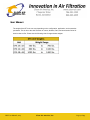
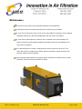
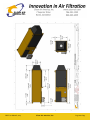
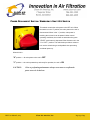
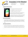
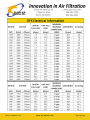
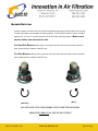
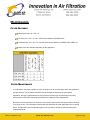
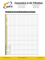
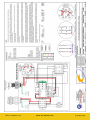
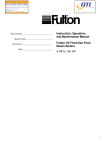
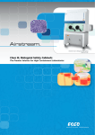
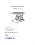
DFX User Manual TABLE OF CONTENTS TABLE OF CONTENTS.............................................................................................................................................. 2 SHIPPING RECEIVING, AND INSPECTION ................................................................................................................ 4 RECEIVING AND INSPECTION..............................................................................................................................................4 INSTALLATION GUIDELINES ................................................................................................................................................4 DFX UNIT DESCRIPTION ......................................................................................................................................... 5 FEATURES AND SPECIFICATIONS ............................................................................................................................ 6 GENERAL FEATURES ........................................................................................................................................................6 BLOWER / MOTOR SPECIFICATIONS ...................................................................................................................................6 UNIT WEIGHT ................................................................................................................................................................7 INSTALLATION ....................................................................................................................................................... 8 MOVING THE DFX UNIT ..................................................................................................................................................8 DFX ASSEMBLY ..............................................................................................................................................................9 ELECTRICAL CONNECTIONS .................................................................................................................................. 12 POWER DISCONNECT SWITCH / EMERGENCY SHUT OFF SWITCH ............................................................................................13 POWER START/STOP SWITCH..........................................................................................................................................14 STARTUP PROCEDURES ..................................................................................................................................................14 SHUTDOWN PROCEDURES...............................................................................................................................................14 BLOWER ROTATION ......................................................................................................................................................16 MAINTENANCE .................................................................................................................................................... 17 FILTER FEATURES ..........................................................................................................................................................17 DFX User Manual, 2014 Clean Air America, Inc. Page 2 of 23 FILTER MAINTENANCE ...................................................................................................................................................17 WHERE TO START .........................................................................................................................................................18 HOW TO DETERMINE THE FILTER CHANGE INTERVAL .............................................................................................................18 HOW TO REPLACE FILTERS...............................................................................................................................................19 MAINTENANCE – CLEANING METAL MESH FILTERS .............................................................................................................20 APPENDIX A: FILTER MAINTENANCE LOG SHEET .................................................................................................. 21 APPENDIX B: WIRING DIAGRAMS (DEC 2009+) ................................................................................................... 22 DFX User Manual, 2014 Clean Air America, Inc. Page 3 of 23 SHIPPING RECEIVING, AND INSPECTION RECEIVING AND INSPECTION Congratulations on the purchase of your new Clean Air America DFX System! Upon receipt of the DFX, remove the master packing list from the unit and reconcile it with the total shipment. Report any discrepancies to Clean Air America as soon as possible. Remove the packaging from the unit; then, if applicable, remove the unit from the pallet. Carefully inspect the unit and any other items shipped with the unit for any damage that may have been incurred during shipping. If damage is found, report it to the shipping company and Clean Air America immediately. Plenums and duct adaptors may be packaged and shipped on a separate pallet depending on the order. Some filters may require being shipped separately. INSTALLATION GUIDELINES Prior to using your DFX unit, it must be fully assembled and placed in its final operating location. Adequate electrical must also be connected to the unit. These connections are defined in “Electrical Connections” section of this manual. DFX User Manual, 2014 Clean Air America, Inc. Page 4 of 23 DFX UNIT DESCRIPTION DISCLAMER: The Clean Air America DFX Unit is designed to accumulate smoke residue/particles and other by-products of the manufacturing process. The nature of these accumulations may be flammable. Operating the DFX Unit with these materials could result in a fire inside the unit. The DFX Unit is not recommended for use with highly combustible materials, explosive materials or particles. The Clean Air America DFX Unit consists of: A DFX Unit Housing Motor / Blower System Inline Filters Differential Magnehelic Gage The “dirty air” inlet is located at one end of the unit, and the “clean air” outlet is located at the opposite end. Adaptation plenums may need to be install at either end for proper duct attachment. Additionally, the optional silencers or exhaust deflectors may be installed on the outlet end. Large opening doors provide easy access to the internal filters and motor compartment for filter changes and maintenance. DFX User Manual, 2014 Clean Air America, Inc. Page 5 of 23 FEATURES AND SPECIFICATIONS GENERAL FEATURES Powder-Coat finish Inside and Out Silencing: Built-in Acoustical Lining Heavy Steel Construction Motor Starter and Overload Customizable Filters 70 - 80 dB Noise level on OSHA scale BLOWER / MOTOR SPECIFICATIONS Backward Incline, Air Foil High Efficiency Plug type Blower(s) Single Phase 115, 208, or 230 Volts 3 Phase 208, 230, or 460 Volts 3450RPM 3600-RPM NEMA MG-1; 230-460 V/60/3 (std.) DFX User Manual, 2014 Clean Air America, Inc. Page 6 of 23 UNIT WEIGHT The weight of the DFX unit can vary depending on the configuration, application, and accessories purchased. This is due to the wide selection of motors, blowers, filters, and accessories Clean Air America has to offer. Please see the following chart for approximate weights. DFX User Manual, 2014 Clean Air America, Inc. Page 7 of 23 INSTALLATION MOVING THE DFX UNIT Clean Air America’s DFX units are shipped using via freight and may arrive on a flat bed trailer. The units are partially crated, on a pallet, and in the horizontal position. Use a fork lift truck, driven by a qualified individual, to remove the crate / pallet from the truck. Occasionally, fork extensions are helpful. Once the DFX unit is inside the facility, ready to be uncrated, please proceed cautiously. DFX Units are heavy and tend to be weighted more to the motor end. The motor is located at the exhaust end of the unit. There are (4) steel plate eyelets vertical at the top of unit. These are the top lifting lugs. There are also (4) steel plate eyelets horizontal on the bottom of the unit. These are the floor mounting point. Properly sized chain or cable can be attached to a lifting tool on a fork lift. The chain or cable can then be connected to the eyelets of the unit. The forklift truck can then be used to lift and move the unit. Other methods include attaching a chain hoist or come along, or both to the eyelets provided at the top of the unit. Please be sure the chain hoist, come along, or chain/cable, is rated for that amount of weight to be lifted. SLOWLY hoist the unit up, supporting it whenever and wherever possible. DO NOT let the unit slam suddenly when placing the unit into position. Please proceed cautiously. DFX User Manual, 2014 Clean Air America, Inc. Page 8 of 23 DFX ASSEMBLY The DFX Unit may require some assembly depending on the application. A standard unit will come with an exhaust cover and inlet cover pre-installed. If a unit has an inlet plenum, then no inlet cover will be installed. The plenum may be shipped separately depending on the size and application and may need to be installed. If a unit has an exhaust plenum or silencer, then no exhaust cover will be installed. The plenum or silencer may be shipped separately depending on the size and application and may need to be installed. To install the plenums or silencer, simply place the device onto the end of the unit. The device will need to be supported from below. Align the bolt pattern. Attach the device with bolts, flat washers, and lock washers. Some plenums exhaust devices may require proper orientation for a planned duct or airflow orientation. Please see the project leader for details. DFX User Manual, 2014 Clean Air America, Inc. Page 9 of 23 DFX User Manual, 2014 Clean Air America, Inc. Page 10 of 23 DFX User Manual, 2014 Clean Air America, Inc. Page 11 of 23 ELECTRICAL CONNECTIONS Clean Air America DFX units can be set up to operate on various power sources. Please see the following electrical chart based on the specified power. The incoming power is connected to the unit at the electrical box located on the front of the unit. To ensure proper operation, a certified Clean Air America, Inc. installer or professional electrician should perform power connections. Any damage incurred from improper electrical power connection will void the warranty of the DFX unit. A wiring diagram is provided with this manual. The full load amperage varies depending on the unit configuration. DFX User Manual, 2014 Clean Air America, Inc. Page 12 of 23 POWER DISCONNECT SWITCH / EMERGENCY SHUT OFF SWITCH This switch controls the main power to the DFX unit. When the switch is in the “0” position, the main power to the unit is disconnected. When in the “1” position, main power is reaching the unit and it can be started. Under normal operating conditions, the unit will not start when the green "START" push button is depressed if the disconnect is in the "0" or "OFF" position. This switch also provides a means to lock out the switch using a small padlock thus preventing accidental power up. When dial is in: “0” position — all main power to the unit is OFF “1” position — the unit is powered up and ready for operation, the unit is ON CAUTION: Prior to performing maintenance always use a meter to confirm the power source is locked out. DFX User Manual, 2014 Clean Air America, Inc. Page 13 of 23 POWER START/STOP SWITCH This switch controls the actual operation of the motor/ blower The green “START” button begins the DFX unit operation The red “STOP” button stops the DFX unit operation The center light will illuminate when the “Start” button is depressed. The light will remain illuminated until the “Stop” button is depressed. The optional remote start/stop switch can be installed to control operation of the motor/ blower. The light on the remote start/stop switch will not illuminate as it does on the unit mounted power stop/start switch. STARTUP PROCEDURES The main unit power must first be turned "ON" by activating the Power Disconnect / Emergency Shut Off switch. The DFX unit can then be started easily. To properly start the DFX unit, simply depress the green "RUN" button. The blower will start immediately, but may take a minute or two to reach full speed. SHUTDOWN PROCEDURES The DFX unit can be shutdown easily. To properly shutdown the DFX unit, simply depress the red “STOP” button. The blower will not stop immediately, and may take several minutes to fully stop. The unit power can be stopped also be deactivating the Power Disconnect / Emergency Shut Off switch. DFX User Manual, 2014 Clean Air America, Inc. Page 14 of 23 DFX User Manual, 2014 Clean Air America, Inc. Page 15 of 23 BLOWER ROTATION If blower rotation is incorrect, the unit will suffer a significant performance loss as well as an increase in noise level. Make sure the blower is rotating properly. To check blower rotation, have a colleague start the unit, count to '4', and then stop unit. As the fan slows, watch the rotation. Make sure to check rotation from the exhaust side. For Non-Blue Blowers: When power is properly connected, the blower will rotate clockwise when viewed from the exhaust of the DFX unit. For Blue Blowers: When power is properly connected, the blower will rotate counter-clockwise when viewed from the exhaust of the DFX unit. [Not Blue] [Blue] PLEASE NOTE: IT IS VERY IMPORTANT TO VIEW THE ROTATION FROM THE EXHAUST OF THE WELD STATION! DFX User Manual, 2014 Clean Air America, Inc. Page 16 of 23 MAINTENANCE FILTER FEATURES Metal Mesh Filter, 24" x 24" x 2" Pre-Filter, 24" x 24" x 4", 60% - 65% efficient based on ASHRAE scale Cellulose Filter, 24" x 24" x 12", Pleated, 95% efficient based on ASHRAE scale, MERV 14 Other Filters are available depending on the application. FILTER MAINTENANCE It is important to the proper operation of your air filtration unit to keep the filters clean and replaced on a proper interval. The point when the filters must be changed is dependent on your specific application, the type of particulate that is being removed, and the type of filters being used. Easy access system of the DFX Units helps with faster filter replacement and maintenance. Because of all of these factors, the customer must monitor and document the system airflow readings for a period of time. The information collected will help determine the most appropriate time to change filters. This process will ensure that the system runs at maximum efficiency while minimizing filter replacement costs. DFX User Manual, 2014 Clean Air America, Inc. Page 17 of 23 During maintenance, examine the metal mesh filters at the inlet of the unit. These filters should be washed when they become visibly dirty / contaminated. The gauge does measure across the metal mesh filters; however, visual inspection is required. Replacement filter of all types are available from your Clean Air America sales representative. WHERE TO START Start by making copies of the attached log sheet. This log sheet should be filled out for each filtration unit you have in your system. Make a physical check to ensure that the smoke / particulate is being removed through the inlets and intake points. This can be done by a simple visual check during normal operation. There should be a reduced level of visible smoke when the unit is in operation. HOW TO DETERMINE THE FILTER CHANGE INTERVAL Once you have verified that the unit is picking up the fumes. At this point, take note and document the pressure differential readings on the gauge. This will be the base line reading. The magnehelic differential pressure gauge measures the pressure loss across all of the filters together. The base line reading is a reference point of the reading with clean filters. What determines the maximum acceptable pressure differential reading? The answer is a reading slightly less than the point where the unit stops drawing in an acceptable level of smoke plume. When the draw becomes unacceptable, then the filters should be cleaned or changed. Initially, you should take readings on a weekly basis, or at any point where the smoke plume is visibly not being removed from the work area. This data will be used to predict the time to change the filters. Remember, no two applications are exactly alike. Because of this your own experience will be needed to optimize filtration, and minimize filter replacement costs. The process for determining your specific filter change interval is based on many variables. Please feel free to establish a filter change interval that meets you application and desired performance results. By properly monitoring the filters you will reduce filter costs and improve the efficiency of the units. Proper filter replacement is important to optimal performance of the DFX Unit. DFX User Manual, 2014 Clean Air America, Inc. Page 18 of 23 HOW TO REPLACE FILTERS 1) Press the red 'STOP' button and allow blower to spin down. 2) Rotate the Emergency Stop / Disconnect to the '0' or 'OFF' position. 3) Open the filter door by simply rotating the filter door handles. This will de-latch the door. 4) Swing the door open to reveal the filters. 5) Slide a large plastic bag over the near end of (1) filter, and slide the filter into the bag over the filter. The filter must be slid horizontally into out the filter door opening. 6) Remove the filter and tie the bag closed. 7) Slide in the new or cleaned filter. Make sure the filters are installed according to the air flow direction markings on the filter (if applicable, such as with the metal mesh filters). 8) Repeat steps 5, 6, and 7 until all filter to be replaced have been removed. 9) Some excess dust / debris may need to be removed while the filters have been removed from the unit. This can be done by sweeping the dust out or through the suction of a proper vacuums system. 10) Close and secure the filter door. 11) Rotate the Emergency Stop / Disconnect to the '1' or 'ON' position. 12) Press the green 'START' button and allow blower to spin up. DFX User Manual, 2014 Clean Air America, Inc. Page 19 of 23 MAINTENANCE – CLEANING METAL MESH FILTERS Examine the metal mesh filters at the inlet of the unit. These filters should be washed when they become visibly dirty / contaminated. The metal mesh filters are designed for spark arresting. Because these filters are the first in line to be soiled by smoke or dust, they should be cleaned periodically. How often they need to be cleaned is dependent upon the amount of welding performed and the given application. Clean Air America recommends that facilities inspect the metal mesh filters monthly, and clean as needed. The metal mesh filters can be washed with a garden hose or, if carefully used, a pressure washer. Be sure they are dry before placing them back into the unit. Depending on the application, it may be possible to clean the metal mesh filters by first simply shaking the filters, then spraying them with an air pressure hose. Whatever method you prefer, it is IMPORTANT that they be cleaned periodically. If they are not cleaned, they can affect the performance of the unit, reducing the CFM (cubic feet per minute) of air movement. DFX User Manual, 2014 Clean Air America, Inc. Page 20 of 23 APPENDIX A: FILTER MAINTENANCE LOG SHEET DFX User Manual, 2014 Clean Air America, Inc. Page 21 of 23 APPENDIX B: WIRING DIAGRAMS (DEC 2009+) Power is brought into the electrical box as 460/230/208 3 Phase or 230/208/115 Single Phase. See the electrical section for more details. There are no fuse or circuit breakers inside the unit. The DFX must be connected to a properly sized circuit breaker. The overload may need to be reset. The Eaton overloads have an automatic reset function, which is initially turned off. If this has not been set, the overload will require being reset via the white button with the red screw-setting switch. This switch is also used to set the Auto / Manual Function. A unit can be wired for both High Voltage (460VAC 3 Phase) and Low Voltage (230/208VAC 3 Phase). For changing the wiring of the unit, refer to the wiring diagram for and motor wiring. NOTE: If the unit is being changed from High to Low Voltage (or vice versa), the contactor and overload may need to be changed. This is because the lower voltage requires twice the amperage. If the unit is being converted to low voltage, the power wiring should be checked for proper gage wires. The wiring in the motor connection must be changed as well. Wire numbers have been added to aid in both the diagnostic issues as well as the maintenance and service issues while in the field. The wire numbers will be shown in small Black numbers at each end of the wire. The wires will be numbered by the 'node', meaning that several wires connecting into one point will have the same number. DFX User Manual, 2014 Clean Air America, Inc. Page 22 of 23 DFX User Manual, 2014 Clean Air America, Inc. Page 23 of 23