1
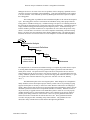
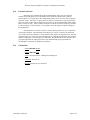
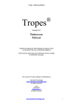
ABSTRACT
Thrust & Torque Calculations for MOV’s using Microsoft Office Products
Prepared by
Michael C. Richard
Teledyne Brown Engineering
Desktop computing using Microsoft Office products have changed the way that engineering
calculations are performed. But, is the change for the better or the worse? Engineering Managers are faced
with the task of “computerizing” engineering calculations all the time. This paper presents some guidance
on how to choose the method that best suits your calculation needs.
Specifically, three methods of calculating thrust and torque for MOV’s will be presented. The
three methods consist of an Excel model, an Access model, and a final model which uses Microsoft Visual
Basic combined with Access (Microsoft Jet) and Excel. Pro’s and con’s will be presented for each method.
Finally, the subject of software validation and verification will be presented with discussions on
how this subject applies to the four methods of calculation presented above.
The information presented in this paper should provide the Engineering Managers, as well as the
engineers responsible for “computerizing” the calculations with the tools they need to make a successful
decision.
1.0)
Introduction
Engineering calculations have changed significantly over the last ten years. With the emergence
of desktop PC's, many different software products have been developed to assist engineers with
calculations. In particular, Microsoft has developed a family of "desktop" software products
named Office 97 to assist with the many facets of business calculations.
Software products, like Office, allow engineers to develop and program their own calculations,
instead of relying solely on software engineers who may not have a background in the field of
interest.
This calculation evolution has on one hand empowered the engineer, but on the other hand has
added requirements for new skills. If you were going to develop an engineering calculation or you
were going to manage the development of an engineering calculation, where would you start?
Microsoft, like many other software developers provide multiple tools to accomplish the same
task. Even if you do select a particular tool, there are a seemingly infinite number of ways to
approach the engineering calculation. Given this situation, which approach should you choose?
Remember, as a developer or a manager, you have a finite budget and a finite time table.
To make these decisions, you need a software development model.
1998 MUG Conference
Page 1 of 8
Thrust & Torque Calculations for MOV’s using Microsoft Products
2.0)
Software Development Model
There are many models available for developing software as presented in References [1][2]. One
of the simplest models is defined as the Waterfall model and is illustrated as follows:
Requirements Analysis
Documentation
Requirements Definitions
Design
Coding
Testing
Reviews &
Inspections
Maintenance
For commercial grade software, the phases of the Waterfall model are summarized as follows:
• Requirements Analysis: Concept based on market research usually stated in the customers
terminology (i.e. The software must provide a live screen of thrust vs time during testing).
• Requirements Definition: Marketing concept restated in the software developers terminology
(i.e. The software must provide a strip chart control for viewing specific channel data during
testing which updates at a rate of 500 samples/second)
• Design: Define system architecture necessary to meet the requirements (for example
Operating System: Windows NT/98/95/3.11,DOS 6.22
Main Development Tools: C/C++/Visual Basic/Access/Excel/Word/…
Third Party Development Tools: ActiveX Controls,…
Additional Hardware: Data Acquisition Boards,…
• Coding: Write code to implement the Design phase.
• Testing: Even though the Waterfall model illustrates that testing begins after the coding has
been completed, in reality, verification tests are developed and implemented during the coding as
completed modules become available. The software validation plan is developed to define the
overall validation testing process. The software validation process begins when the coding
process has been completed.
• Maintenance: Provide support for completed products until the product is retired.
You may be thinking to yourself, "I'm only writing a simple Excel spreadsheet, so this doesn't
apply to me." The purpose of presenting a software development model is to demonstrate that
coding is only a piece of the overall development process and that it is not the first piece that
should be done. The can be restated as follows:
1998 MUG Conference
Page 2 of 8
Thrust & Torque Calculations for MOV’s using Microsoft Products
• Define BEFORE Design
• Design BEFORE Code
The purpose of presenting a generic software development model is to provide a framework
for preparing a Torque & Thrust Calculation for Motor Operated Valves (MOV) using Microsoft
Office products.
3.0)
Torque & Thrust Calculations for MOV's using MS Office
The generic software development model presented was illustrated for commercial grade
software. The Testing phase of the software development cycle is a recommended practice for
commercial grade software but does not necessarily have to be performed. The incentive for
performing Verification and Validation testing is economics. Untested software will contain
defects and may not meet the specification of the customer. Unhappy customers and high
maintenance costs usually justify performing some amount of testing during the development
process. The amount of testing performed is usually a function of the product shipping date.
This is not the case for software used to calculate Torque & Thrust for MOV's. This software
directly affects safety related design calculations in support of the safe operation of a nuclear
power plant. Verification & Validation Testing is a requirement of the QA procedures which
control design calculation software. These QA procedures are usually a subset of the existing
Nuclear and Engineering Standards which provide guidance and control of software used in
nuclear applications. Refer to the reference section for a partial listing of these standards. It is not
the intention of this paper to discuss the contents of the standards or the QA procedures other than
to say that they exist and they contain requirements which must be met with regard to software
development and control, especially with regard to Verification and Validation testing.
The Requirements Analysis phase of the software development cycle is usually the most
organized phase of the cycle. As a result of the GL 89-10 program, most utilities have a well
organized Torque & Thrust Calculation Methodology or Procedure. In many cases there may
exist previous computerized calculations in a form other than one of the MS Office products.
In all cases, there should exist hand calculations which follow a revision of the Torque & Thrust
Methodology.
Warning : If you are in the middle of developing or revising this document, please do not
attempt to go any further into the software development cycle until the revisions have been
completed. Continuing with the software development cycle before revisions have been
completed can have a dramatic impact on the overall cost of the project.
The Requirements Definitions and Design phases usually get the least attention but require the
most attention. Decisions made here can lead to the overall success or failure of the entire project.
Here are some steps that can lead to success in the overall software development cycle:
Step 1: Make time for the Requirements Definitions phase and the Design phase
Step 2: Arrange meetings with the following attendees:
• Managers who are responsible for the overall project
• Engineers who have developed or are well versed in the methodology or procedure
• Software Developers who are well versed in the available software development tools
1998 MUG Conference
Page 3 of 8
Thrust & Torque Calculations for MOV’s using Microsoft Products
Step 3: Review the methodology or procedure on a chapter-by-chapter basis and Decide whether
to include or exclude the contents of the chapter in the software. The software will be simpler to
develop by excluding any special case formulations in the methodology. Consider the following
circumstances:
• The methodology may contain multiple chapters on calculating torque requirements for
quarter turn valves; however there may be only a few of these valves in the 89-10
program. Therefore, you may decide to exclude these chapters from the software in lieu
of a more simple hand calculation.
• The methodology may contain multiple chapters on calculating torque & thrust
requirements for rotating-rising globe valves; however there may be only a few of these
valves in the 89-10 program. Therefore, you may decide to exclude these chapters from
the software in lieu of a more simple hand calculation.
• You may have time or budget constraints which prohibit the entire contents of the
methodology form being included in the software at this time.
Step 4: Establish data to be INPUT to the software and data to be OUTPUT from the software.
This means organizing the calculations which were selected in Step 3 to determine which
parameters are on the left side of the equal sign and which parameters are on the right side of the
equal sign. While organizing the calculations, it is recommended to order the calculations for
dependency. It is also recommended to establish the following characteristics for both the INPUT
and OUTPUT:
Characteristic
•
•
•
•
•
•
•
Name (abbreviation)
Units
Brief Description
Type
Size
Range
Format
Example
StemDia
(in)
Valve Stem Diameter at Packing
Number
N/A
Min = 0.5; Max = 10.0
2 decimal places
Step 5: Develop a User Interface. A user interface can be as simple as a diagram on a chalkboard
and does not require any working knowledge of the software development tools. This will
establish what you want to see on the screen when you operate the software. A simple approach
here is to look at what is available in the existing methodology and supporting documentation.
There may exist a format that the existing staff is familiar with that can be replicated as a user
interface. The more familiar looking the user interface is, the easier the existing staff will accept
and utilize the software.
Step 6: Develop a Report Interface. This will establish what you want to see on paper when you
perform a print operation from the software. A simple approach here is to use an existing hand
calculation as a typical report. There may be a need for more than one report interface, i.e. Detail
Report and Summary Report. Depending on the software QA requirements, this report interface
will most likely be the document to be used for software Validation testing .
Step 7: STOP for a minute. Up to this point , all of the thought process that has been performed
should have been in plain English. If you are already talking computer languages, then you have
jumped the gun. It is critical to define and design in plain English before getting into software
development tools. However, now is the proper time to evaluate software development tools. It is
a good idea to purchase as many software development tools as possible. Do not try to re-invent
the wheel with just the minimum set of tools. There is an entire industry out there just inventing
1998 MUG Conference
Page 4 of 8
Thrust & Torque Calculations for MOV’s using Microsoft Products
tools for software developers to use. Do not underestimate the human factors when making this
decision; who will be maintaining the software when the project has been completed? Will
engineering be maintaining the software or will it be maintained by someone else (i.e. on-sight
software services, off-sight software services, independent contractors,…) This is discussed in
more detail in the Coding phase notes.
Step 8: Develop a reasonable timeline which establishes the overall time frame for the software
development project. Include the vacation times of the individuals involved as well as spare time
for unexpected events. It is also recommended to break the overall project into tasks which can be
monitored for progress during the coding phase. Locate the breaks such that it represents the
completion of a particular module, so that verification testing can be performed on the completed
module while the coding phase is still in progress on another module.
Step 9: Document Steps 1-8. This documentation will serve as the Requirements Specification
which will be used to develop Verification Tests and the Overall Validation Plan.
The Coding phase of the software development cycle should be the most straightforward
phase because of the preparation which has preceded it, however the biggest problem with this
phase is finding software developers who are well versed in the available software development
tools. The following table illustrates the programming skill level necessary to develop software
using the indicated software products.
Software
Skill Level
Excel
Excel/VBA
Access
Access/VBA
Visual Basic
Managers need to pay close attention to who they are assigning as the software developer.
Engineers who are well versed in the methodology are ideal candidates for the role as software
developer as long as they also possess the necessary software development skills. If they do not
possess the necessary software development skills, then the project will become an educational
experience and not a software development project. It is much more efficient and cost effective to
send an engineer to Microsoft Training Courses for a month before he starts the project than to
allow him to learn software development skills through experience on the project. The end result
for training is a win-win situation because the project will have a much higher success rate (makes
the manager look good) and the engineering group as a whole will benefit from the increased
knowledge of an individual (makes the manager look better). Also it is more likely that the
engineer will be around for the Maintenance phase than if someone was brought in from another
department. In addition to training, there are multitudes of textbooks available which discuss the
Microsoft Office family of products. If you are one who learns from printed text, refer to the
Reference Section for a listing of books pertaining to the subjects.
1998 MUG Conference
Page 5 of 8
Thrust & Torque Calculations for MOV’s using Microsoft Products
Managers also have to be aware of the converse problem, which is assigning a qualified software
developer who has no knowledge of the methodology . This puts an undo burden on the engineer
to act as a translator. This could end up effectively doubling the man-hours required to complete
the Coding phase.
The Testing phase is probable the most misunderstood phase of the software development
cycle. The testing phase consists of Verification and Validation testing. Most people relate the
testing phase to Validation testing only. Validation testing is the process of evaluating software at
the end of the development process to ensure that it meets the requirements. Verification testing is
simply validation testing performed during the development process. Verification testing can
indicate whether a particular module meets its requirements as well as detect the presence of any
defects. It is much more cost effective to fix a non-compliance found during verification testing
than it is to fix the same non-compliance found during validation testing. The following figure
illustrates the relative cost factors to find a fix a non-compliance at each of the indicated phases:
Requirements Analysis
$1
Requirements Definitions
$5
Design
$20
Relative Cost Factor
to find and fix
software defects
Coding
$50
Testing
$100
Maintenance
The simplest form of verification and validation testing is to compare the printed software output
to existing hand calculations or previously generated computer generated results which have
already been verified.. The printed software output can also be compared to the user interface
results displayed on the screen in order to verify the user interface. It is recommended to develop
as many validation problems as necessary to test all of the logic paths within the software (i.e. gate
valve, globe valve with flow under the seat, globe valve with flow over the seat, butterfly
valve,…)
The Maintenance phase is the most forgotten phase. Most managers are so delighted to
finally finish the software development project that they cannot conceive of providing on-going
support, but this phase is necessary in these times where hardware and software are changing so
rapidly. Many software tool developers are foregoing backwards compatibility in order to provide
much better products suited for the 32 bit platforms (Windows NT/98/95). With this in mind , it
may be necessary to upgrade software in the maintenance phase in order for it to work properly.
Another important activity of the maintenance phase is the evaluation of any defects which are
found by users during normal use of the software. There are specific guidelines that must be
followed if a defect is found after the software has been is use. These guidelines should be
covered in the QA procedure controlling safety related software. The guidelines are also
discussed in many of the References under Nuclear & Engineering Standards.
1998 MUG Conference
Page 6 of 8
Thrust & Torque Calculations for MOV’s using Microsoft Products
4.0)
Last but Not Least
Referring to the original Software Development Model, there exists two functions
common to all of the phases; one is labeled Reviews & Inspection and the other is labeled
Documentation. It is a great idea to have independent people come in to review what is going on
from time to time. Not only is it a great idea, but it may be a requirement of your QA procedure.
They can provide support and encouragement as well as prevent misunderstandings which might
lead to a costly recovery. Many software developers see this as an invasion of privacy, but when
it is done properly, everyone benefits. To be a good reviewer & inspector requires training just
like anything else.
Documentation is a four letter word to a software developer however it is a requirement
of most QA procedures. Documentation can be they key to success or failure if an unexpected
event occurs, such as the departure of a key member of the software development team. Someone
will need to take over where the previous member left off. Without documentation, this would be
difficult to impossible. The entire project would suffer. Documentation will also assist the team
of people responsible for writing the software user manual and the people responsible for
developing the verification & validation test problems.
5.0)
Conclusions
• Define BEFORE Design
• Design BEFORE Code
• Code to the Specification : nothing more/nothing less!
• Document what you do
• Provide Training for new developers
1998 MUG Conference
Page 7 of 8
Thrust & Torque Calculations for MOV’s using Microsoft Products
6.0)
References
1) Rakitin, Steven, R.,"Software Verification and Validation, A Practitioner's Guide", Artech
House, Boston, 1997
2) Rakitin, Steven, R.,"Software Verification & Validation, An Overview for Practitioners",
Workshop Notes, Copyright Steven R. Rakitin, [email protected]
References for Software Development using Microsoft Office Products
3) Solomon, Christine, "Microsoft Office 97 Developer's Handbook", Microsoft Press,
Redmond,Washington,1997
4) Microsoft Corp.,"Microsoft Office 97 Visual Basic Programmer's Guide"; Microsoft Press,
Redmond,Washington, 1997
5) O'Brien,T.M. & Pogge,S.J. & White,G.E.,"Microsoft Access 97 Developers Handbook",
Microsoft Press, Redmond,Washington, 1997
6) Smith,Robert & Sussman,David,"Beginning Access 97 VBA Programming",Wrox Press
Ltd.,Birmingham,UK,1997
7) "Visual Basic Programmer's Guide, Version 5.0",Document No. DD93011-1296, Microsoft
Corp., Redmond,Washington, 1997
8) Craig,J.C. & Webb,J.,"Miscosoft Visual Basic 5.0 Developer's Workshop", Fourth Edition,
Microsoft Press, Redmond,Washington,1997
9) Mann, Anthony,"Visual Basic 5.0 Developer's Guide",Sams Publishing,Indianapolis,1997
10) Haught,D. & Ferguson,J.,"Microsoft Jet Database Engine Programmer's Guide",Second
Edition,Microsoft Press,Redmond,Washington,1997
Nuclear & Engineering Standards Summary (Partial List)
11) ANSI/IEEE-ANS-7-4.3.2, Application Criteria for Programmable Digital Computer Systems
in Safety Systems of Nuclear Power Plants
12) ANSI/ANS-10.2,Recommended Programming Practices to Facilitate the Portability of
Scientific and Engineering Computer Programs
13) ANSI/ANS-10.3,Guidleines for the Documentation of Digital Computer Programs
14) ANSI/ANS-10.4,Guidelines for the Verification & Validation of Scientific and Engineering
Programs for the Nuclear Industry
15) ANSI/ANS-10.5,Guidelines for Considering User Needs in Computer Program Development
16) ANSI/ASME NQA-1,Quality Assurance Program Requirements for Nuclear Facilities
17) ANSI/ASME NQA-2 Part2.7,Quality Assurance Requirements of Computer Software for
Nuclear Facility Applications
18) IEEE STD 1033,IEE Recommended Practice for Application of IEEE STD 828 to Nuclear
Power Generating Stations
19) NUREG/CR-4640,Handbook of Software Quality Assurance Techniques Applicable to the
Nuclear Industry
20) Regulatory Guide 1.152,Criteria for Programmable Digital Computer System Software in
Safety-Related Systems of Nuclear Power Plants.
21) ANSI/IEEE Std 729,Glossary of Software Engineering Terminology
22) ANSI/IEEE Std 730, Software Quality Assurance Plans
23) ANSI/IEEE Std 828,Software Configuration Management
24) ANSI/IEEE Std 829,Software Test Documentation
25) ANSI/IEEE Std 830,Software Requirements Specifications
26) ANSI/IEEE Std 1008,Software Unit Testing
27) ANSI/IEEE Std 1012,Software Verification And Validation Plans
28) ANSI/IEEE Std 1016,Software Design Description
1998 MUG Conference
Page 8 of 8