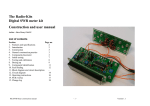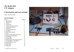
1
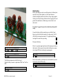
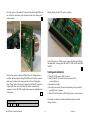
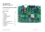
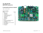
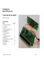
The Radio-Kits Digital SWR meter kit Construction and user manual Author - Steve Drury G6ALU List of contents Section Page no. 1. Features and specifications 2 2. Introduction 2 3. Construction 3 4. General construction practice 3 5. Component placement 3 6. Initial testing 7 7. Testing and calibration 8 8. Boxing up 9 9. Component Identification 11 10. Fault finding 12 11. Block diagram and circuit description 12. Circuit diagram 14 13. Operating instructions 16 14. PCB overlay 17 15. Change log 18 RK-SWR Meter construction manual -1- Version 1.0 Introduction Features • • • • • • • • An SWR meter is an essential requirement for any radio shack; this is a design for a general-purpose instrument that will read SWR and power. Being digital it is easy to incorporate several functions that are not only useful but in the case of the reverse power alarm could avoid an expensive repair bill. Displays SWR, forward power, reverse power and supply voltage Peak reading power meter Bar graph or numerical format Reverse power alarm with adjustable threshold Auto turn on in presence of RF – sensitivity about 1 Watt Optional turn off after preset time – 10-60 Seconds Backlit LCD display with variable brightness Reverse polarity protection For input power below about 20W the unit can be powered from a PP3 type battery, for 200W a power source > 13.8Vwill be required as the op. amp needs this to achieve the required output voltage swing. Two backlit display options are offered; the first is yellow / green which has high contrast and has good viewing angles although consumes 100mA at full brightness. The other display has a blue back-light consuming only 20mA at maximum brightness so is therefore more suitable for battery use. Typical Specifications (13.8V supply) Power handling - Operating frequency Supply voltage Current consumption Through loss - QRP – 100W. Will read 200W Peak if power supply >13.8V HF (1.8 – 30MHz) 7 – 16V Dependent on display voltage and backlight colour – 110mA at max brightness for yellow / white backlight 0.2dB typical (small signal) RK-SWR Meter construction manual The detector “head” has been designed as a separate PCB allowing it to be remote mounted if required, alternatively it may be mounted in the same box as the display PCB. Provision has been made to fit a screen over the back of the transformers; this will allow the detector PCB to be placed in close proximity to the display board without interaction. -2- Version 1.0 be noticed that the solder “wicks” up the hole through to the top surface, this is normal. Construction These instructions have been targeted at those with some construction experience and who can identify the different components. Where out of the ordinary parts have been used a short description follows the component value. For a start place just a few components in place before soldering them, as experience grows you may find it more productive to fit a larger number at a time. As each component is fitted put a mark in the box provided, it’s very easy to forget the last component fitted especially if you are distracted. If you make use of the component overlay you will find it helpful if components are highlighted as they are fitted. Components are taken from one bag at a time keeping the others sealed. Everyone has their preferred method of retaining components prior to soldering; I pull the leads through with long nose pliers and put a bend in the component lead to stop it falling out of the board. A good policy is not to crop leads until they have been soldered, this should stop you from missing any soldered joints. Only crop ONE lead at a time, by cropping several leads its possible to “crack” pads off the print which can be a very difficult fault to find. All components except for the display, its socket and tact (short for tactile) switches are mounted on the component side of the board. The PCB silk-screen gives the component locations; in cases where this is difficult to read please refer to the printed overlay that is larger than actual size. Note that components are numbered from left to right then top to bottom of the board. If you have difficulty in locating a component position place a straight edge across the overlay and look along its length, in this way components will be easy to locate. The PCB has been designed to accommodate the components supplied so if it doesn’t easily fit ask yourself if it belongs there! Note that if cleaning the PCB with solvents make sure it doesn’t enter the preset resistors or they may get contaminated and fail when adjusted. General construction practice Leaded or lead-free cored solder may be used, the solder must be designed for electronics – do not use plumbers solder or additional flux as the flux is very corrosive. I use 22SWG (0.7mm) multi-core type solder that seems most suitable for this type of work. A double sided plated through hole (PTH) PCB has been used which provides screening and allows for a small design; however incorrectly fitted components can be very difficult to remove so it’s important to fit them in the right place first time! If a component is inadvertently fitted incorrectly it is easiest to cut off its leads, apply the soldering iron and pull them out from the topside. A small solder sucker or desolder braid can be used to clear the holes out ready for a replacement component to be fitted. When soldering the component leads it will RK-SWR Meter construction manual Where possible fit the components so their values are easily readable. Some components MUST be fitted in the correct orientation as they are polarised; this will be indicated in the text. The components are packed in four bags; each bag contains a list of contents that will show any substitutions that have been made. Component placement Both detector and main PCBs are supplied as one panel, it is suggested to leave these as a single panel until PCB construction is completed. -3- Version 1.0 From bag 1 fit the following components: If a yellow / green backlit display is used fit the following: 56R 0.6W 1% (Green, Blue, Black, Gold, Brown) R18 R32 Resistors are identified by four or five colour bands; if in doubt use a multi-meter to confirm their value. If a blue backlit display is used fit the following: 220R Resistor (Red, Red, Brown, Gold) R18 R32 Positions L1 and L2 have resistors fitted. 100R 1% Resistor (Brown, Black, Black, Black, Brown) R1 R2 R3 R4 R16 R21 L1 L2 10k Resistor (Brown, Black, Orange, Gold) R5 R6 R7 R9 R17 R19 R22 R24 3k3 Resistor (Orange, Orange, Red, Gold) R20 R23 R27 R34 R35 18k Resistor (Brown, Grey, Orange, Gold) R33 R12 R29 100k Resistor (Brown, Black, Yellow, Gold) R8 10k Preset resistor (Marked 103) R25 1k Resistor (Brown, Black, Red, Gold) R28 R30 1k Preset resistor (Marked 102) R26 R31 27k 1% Resistor (Red, Violet, Black, Red, Brown) R11 10nF Capacitor (Marked 103) C1 C2 C3 C12 C13 C15 C21 C4 C18 C9 C19 470R (Yellow, Violet, Brown, Gold) R10 100nF Capacitor (Marked 104) C6 C7 C8 C17 C23 C24 C10 C14 4k7 1% (Yellow, Violet, Black, Brown, Brown) R14 1nF Capacitor (marked 102) C11 C22 8K2 1% (Grey, Red, Black, Brown, Brown) R13 R15 RK-SWR Meter construction manual -4- Version 1.0 Diodes are polarised devices so can only be fitted one way round, match the band on one end of the encapsulation with the bar printed on the PCB. BAT85 Diode (Small glass diodes) D1 D2 D5 D6 D8 D9 78L05 Integrated circuit U2 U3, Ensure the notch is aligned with that printed on the PCB LM358 Integrated Circuit U3 D7 Fit the socket as indicated on PCB overlay 18 Pin socket in position U4 U4 1N4001 Diode D3 D4 From bag 2 fit the following components: Electrolytic capacitors are polarised so may only be fitted one way round. By convention the PCB is marked with a + symbol, the + lead of a capacitor is longest; the capacitor sleeve is also normally marked -. Fit the capacitors against the PCB with zero lead length but don’t put excessive force on the leads as this can make the electrolyte leak out. Transistors should be fitted so their outline matches that printed on the PCB, their type number is marked in small lettering on the flat surface. Don’t confuse transistors (prefix Q) with ICs prefix U). BC327 Transistor Q1 BC547B Transistor Q2 Q3 1uF 63V Electrolytic capacitor C16 C20 Q4 47uF 25V Electrolytic capacitor C5 BC337 Transistor Q5 The display socket is fitted from the underside of the PCB and soldered on the topside. Hold it flat to the PCB whilst soldering. U1 and U2 have 3 legs and look like similar to the transistors. TL431CLP Integrated Circuit U1 RK-SWR Meter construction manual -5- Version 1.0 T1, T3 and T4 16 pin 90° inline socket Disp For clarity these sketches show a reduced number of turns. The tact switches are fitted from the underside of the PCB and soldered to the top. Tact switch SW4 SW5 SW6 PHOTO SHOWING TINNED LEADS. Cut 50mm from the 20SWG tinned copper wire and bend into a “hairpin” similar to the sketch – note the 10mm dimension is internal but in any case isn’t critical. T1 to T4 are wound on toroid cores, T2 is wound in the opposite direction to T1, T3 and T4; see sketch below. The ident for these transformers isn’t marked on the PCB, use the overlay to identify their positions. Pass the hairpin through the center of the toroid and solder all 4 wires to the PCB, make sure the hairpin passes exactly through the center of the toroid; see photo. Fit the toroid so the windings are about 1mm from the PCB. Cut approximately 600mm of 27SWG enameled copper wire and wind 23 turns around a FT50-61 toroidal core, every time the wire passes through the center of the core counts as a turn. Clean the enamel from the ends of wire and “tin” with the soldering iron. RK-SWR Meter construction manual T2 -6- Version 1.0 Initial testing Before connecting power make a careful inspection of soldered joints especially for any solder splashes etc. At this point the microcontroller and display should not be fitted as wrong voltages applied to their pins will cause damage. Measure between supply positive and ground with a multi-meter on Ohms range to ensure there is not a short circuit For safety it’s suggested to power the unit by battery during initial testing. Connect the battery; whilst pressing the power switch (left most button viewed from the front) measure the voltage on pin 14 of U4 (PIC16F819), this should read about 5V. If significantly different investigate the cause before proceeding. Disconnect the battery. FT50-61 23T of 27SWG Enameled wire T1 T3 T4 Fit the 16 way header plug from the back of the display and solder on the front side. Solder one pin first and check that the pins are square to the display PCB before soldering the remaining pins. FT50-61 23T of 27SWG Enameled wire T2 16 Pin Header PL1 The following components are fitted from bag 3. Solder the battery connector to pads marked “Batt” and “Gnd” on PCB. Fit the microcontroller, note that pin one end is identified by a notch on the socket; refer to PCB overlay. PIC16F819 I/P Integrated Circuit U4 PP3 Battrey connector SK5 RK-SWR Meter construction manual -7- Version 1.0 Fit 4 hex spacers to the main PCB; pass the threads through PCB from the switch side and secure on the component side with a shake-proof washer and nut. Plug the display into the 90° socket, see photo. Using 3 short pieces of hook up wire connect the detector PCB with the main board: Connect points RE to REV, GND to GND and FWD to FWD. Testing and calibration Fit the 8 hex spacers to detector PCB in RF socket fixing positions, note that the thread passes through the PCB and is fixed by a nut and shake-proof washer on the component side of board. Only tighten them “finger” tight at this stage. Temporarily hold the RF connectors in place with 3mm screws and solder the center terminal on the component side of the PCB, straighten the connectors and tighten the 8 fixing nuts. • Turn R25 (LCD) contrast fully clockwise. • Turn R26 and R31 (forward and reverse adjust) fully counterclockwise. • Reconnect the battery. • Press the power button; the meter should now power up and will probably show 16 squares. • Adjust R25 anti clockwise until the display shows correct contrast. It’s possible to make a reasonable calibration using the internal voltage reference. S0239 RF Socket SK1 SK2 RK-SWR Meter construction manual -8- Version 1.0 • Connect together pads REV, FWD and TP3V9 (detector PCB may be left connected). • Power up and using the push buttons select FWD on the display top line and REV on bottom line (see operating instructions). • Adjust R26 and R31 clockwise to set forward power to read 23.1 Watts. • Note: With REV and FWD connected to TP3V9 it will not be possible to turn the unit off using the Menu button – power down before disconnecting the links by removing the power source. A template has been provided to help with drilling case holes accurately. Print out the drilling template and confirm the size is correct by measuring the printed dimensions, they should be printed with “Page scaling” set to none in the print menu. Stick the drilling templates to the outside of the case aligning the reference edges with the INSIDE surfaces of the box, this is important; for the templates to be universal no account has been made for case thickness, instructions are printed on the templates. Drill all holes to the sizes indicated on the template, use good engineering practice; start with a small drill and work up in size. Check that the meter is functioning correctly either by fitting between a transmitter and dummy load or transmitter and antenna. If a known accurate power meter is available it can be placed in line with the transmitter, this meter and a dummy load. Using moderate power (20 – 50W) adjust the forward power reading to match that of the reference meter, reverse power is adjusted by reversing the meters connections. The template doesn’t include positions for the DC connector or alarm sounder, find suitable positions for these before drilling any holes! The volume of the sounder can be adjusted by varying the outlet hole; start with a small one (2mm suggested), it can be enlarged if necessary. The DC socket requires a 8mm hole. Whilst making these adjustment make sure the auto power off feature is switched off (default setting). To cut the display I would recommend drilling many holes close to each other just on the inside of the window then using a pair of side cutters join them up. The window can then be squared up using a file. Boxing up The meter hasn’t been designed to fit any particular enclosure; the choice is left to the constructor. Fit the main PCB to case, it is secured by 4 M3 x 6mm screws with flat washers under the heads. As previously mentioned the detector head can be used remote of the meter, interconnections should be made by screened cable and can either be permanently fixed or plugged; a standard 3 or 5 pin DIN type plug is suitable. The meter enclosure (and that for the detector) should be metallic to stop any unwanted noise pickup or radiation. RK-SWR Meter construction manual Fit the detector PCB to case using 8 M3 screws and plain washers, refer to photo. Fit the power socket and wire to the PCB; the center contact is the + terminal. -9- Version 1.0 2.1mm DC socket SK3 The sounder is “glued” to the inside of the case using superglue or similar, using hookup wire connect to the pads on PCB noting the polarity. Piezo Sounder SK3 I have catered for two methods of fitting a front panel; with a little thought I’m sure there are many more. For those wanting to design their own front panel critical hole dimensions and spacing are given on the drilling template. 1. A PDF file of a front panel is provided, this may be printed and glued (double sided tape perhaps) to the front and then covered with a sheet of acetate / overhead projector film trapped under the four fixings screws. 2. A negative image is provided, this can be printed on to acetate or a bubble jet transparency, by reversing the image the non-printed side is nearest the user so protecting the writing. The builder is encouraged to personalise the front to his or her own taste to add some individuality. RK-SWR Meter construction manual - 10 - Version 1.0 ColourValue Black Brown Red Orange Yellow Green Blue Violet Grey White Silver Gold Component identification Components have been packed in to 4 bags, the contents of these bags and order of assembly have carefully been chosen so similar components shouldn’t become confused. For fault finding it will be necessary to correctly identify components and their values after the radio has been built; methods of marking component values are given. Capacitors The ceramic capacitors used in this kit are marked numerically, based in Pico farads. The first two digits are the value and the third is the multiplier, for example 1nF (1000pF) is marked 102 (1, 0 and two zeroes), 10nF is marked 103 (1, 0 and three zeros). 0 ×1 1 ×10 2 ×100 3 ×1000 4 ×10000 5 ×100000 6 ×1000000 7 8 9 Divide by 100 Divide by 10 Tolerance 1% 2% 10% 5% Electrolytic capacitors are marked directly with their value. Resistors Values on all the resistors in this kit use a colour code to indicate value. Examples: 1kΩ 5% (1000Ω) = Brown (1) Black (0) Red (×100) Gold (5% tolerance) 2R2 5% (2.2Ω) = Red (2) Red (2) Gold (divide by 10) Gold (5% tolerance) Note that 1000Ω = 1k, 1000000Ω = 1M, 2K2 = 2200Ω, 2R2 = 2.2Ω etc. Several resistors are 1% tolerance types and are therefore marked with 5 coloured bands; all other types have standard 4 band markings. Diodes All diodes used are axial and have their cathode end marked by a ”band” on the encapsulation. RK-SWR Meter construction manual - 11 - Version 1.0 Values are marked on the bodies although for the small glass diodes (BAT85) they will be hard to read without a magnifying glass. Fault finding Most faults are due to poor soldered connections or components misplaced; it is very rare to be supplied with a faulty component. Before making any measurements look carefully for any poor soldered joints, short circuits or incorrectly fitted components. Transistors and Ics TO92 and terminal identification Component BC327 BC337 BC547 78L05 TL431CLP 1 Emitter Emitter Emitter Input Cathode Lead identification 2 Base Base Base Gnd Gnd Should fault finding be necessary a table of voltages is given below, voltages were measured with both inputs from the bridge connected to TP3V9. 3 Collector Collector Collector Output Reference Voltage tables Transistor Emitter Base Collector Q1 13 12.3 13 Q2 0 0 5 Q3 0 0.6 0 Q4 0 0.7 0 Q5 0 0.7 0.1 LM386 is similar to PIC16F819 but only has 8 pins. RK-SWR Meter construction manual - 12 - Version 1.0 IC Pin Number 1 2 3 U1 3.9 0 2.49 U2 13.1 0 5 U3 4.4 3.9 3.9 4 5 6 7 8 0 3.9 3.9 4.4 13.1 Pin Number U4 1 2 3 4 5 6 7 8 9 0.16 3.9 3 0 0 0 0 5 5 Pin Number 10 11 12 13 14 15 16 17 18 5 5 5 5 5 5 5 1.3 1.3 Block diagram and circuit description To Follow RK-SWR Meter construction manual - 13 - Version 1.0 Circuit Diagram RK-SWR Meter construction manual - 14 - Version 1.0 PCB overlay RK-SWR Meter construction manual - 15 - Versio 1.0 Operating instructions Up Push buttons function The function for the top line of the display sequentially changes on each push of the button. Functions are: Menu Each sequential press advances to the next menu function. SWR – Numerical Pressing the menu button in the off mode will turn the unit on. To turn the unit off press and hold the menu button until “Power Off” is displayed, then release button. The unit can not power off if RF is being sensed on the transceiver input – in this case “Power Off” will not be displayed. Forward power – Numerical SWR – Bar graph Backlight There are 5 backlight levels selected by the up and down buttons: Off to 5 Forward power – Bar graph Reverse power alarm If there is reverse power above the threshold set an alarm will sound. The threshold is adjustable by the up and down buttons in 1 Watt steps with a maximum of 50W Down The function for the bottom line of the display sequentially changes on each push of the button. Functions are: Forward power – Numerical Time to auto off The SWR meter can be made to automatically turn off after a preset period of no operation. The limit is adjustable in 10 second steps up to a maximum of 60 second. This function may also be turned off. Reverse power – Numerical Forward power – Bar graph Reverse power – Bar graph Supply voltage RK-SWR Meter construction manual - 16 - Versio 1.0 The bar graphs are calibrated as follows: SWR Power: BAR Value 1 0.5 1 1:1 2 1 2 1.1:1 3 2 3 1.2:1 4 4 4 1.3:1 5 8 5 1.4:1 6 16 6 2:1 7 32 7 2.5:1 8 64 8 3:1 9 128 9 5:1 10 200 10 10:1 11 Not used 11 15:1 12 Not Used 12 >20:1 RK-SWR Meter construction manual - 17 - Versio 1.0 Version Date of change V1.0 30-09-10 Changes First release RK-SWR Meter construction manual - 18 - Versio 1.0