1
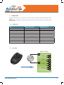
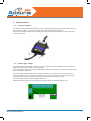
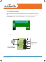
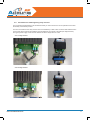
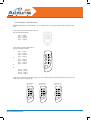
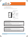
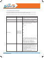
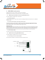
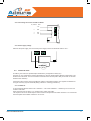
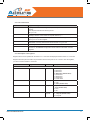
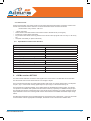
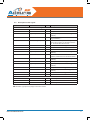
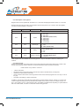
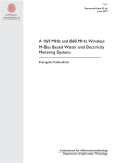
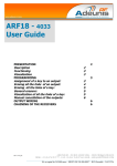
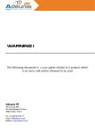
INTRODUCTION
All rights to this manual are the exclusive property of ADEUNIS RF. All rights reserved. Copying this manual (without written permission from the owner) via printing, copying, recording or by any other means, translating this
manual (in full or partially) into any other language, including all programming languages, using any electrical,
mechanical, magnetic or optical devices, manually or any by other methods, is prohibited.
ADEUNIS RF reserves the right to change the technical specifications or functions of its products, or to cease
manufacturing any of its products, or to cease technical support for one of its products without notice in writing
and urges its customers to make sure that the information they have is valid.
ADEUNIS RF configuration software and programs are available free of charge in a non-modifiable version.
ADEUNIS RF can make no guarantees, including guarantees concerning suitability and applicability for a certain
type of application. Under no circumstances can the manufacturer, or the distributor of an ADEUNIS RF program,
be held liable for any damage caused by the use of the aforesaid program. Program names, as well as all copyright relating to programs, are the exclusive property of ADEUNIS RF. Any transfer, granting of licences to a third
party, leasing, hire, transport, copying, editing, translation, modification into another programming language or
reverse engineering are prohibited without ADEUNIS RF’s prior written authorisation and consent.
ADEUNIS RF
283, rue Louis Néel
38920 Crolles
France
Telephone +33 (0)4 76 92 07 77
Fax +33 (0)4 76 08 97 46
Environmental recommendations
All superfluous packaging materials have been eliminated. We have done everything possible to make it easy to
separate the packaging into three types of materials: cardboard (box), expanded polystyrene (filler material) and
polyethylene (packets, foam protective sheets). Your device is composed of materials that can be recycled and
reused if it is dismantled by a specialist company. Please observe local regulations concerning the manner in
which waste packaging material, used batteries and your obsolete equipment are disposed of.
Warnings
Valid for relay receivers with the following references: ARF7341B/7341F/7341D and serial receivers ARF7263K/S
Read the instructions in the manual.
The safety of this product is only guaranteed when it is used in accordance with its purpose.
Maintenance should only be carried out by qualified persons.
Please note, do not install the equipment close to a heat source or in damp conditions.
Please note, when the equipment is open, do not carry out any operations other than those specified in these
instructions.
Gamme ARF18 UG V1.5
38
Only use this equipment inside a building and at a maximum height of 2000 m above sea level.
Please note: do not open the product as there is a risk of electric shock.
Please note: for your own safety, you must ensure that the equipment is switched off before carrying out any work on it.
Please note: for your own safety, all wired relays must cut either from the SELV, or the ELV (eg: 230V mains power supply). The two types of voltage must not be mixed.
Please note: when the aerial is installed outside, it is essential to connect the cable screen to the
building’s earth. We recommend using lightning protection. The protection kit chosen must permit the
coaxial cable to be earthed (eg: coaxial lightning arrester with earthing of the cable at different places on the
aerial at the base of pylons and at the entry, or just before entering the premises).
The product must be equipped with a switching mechanism so that the power can be cut. This
must be close to the equipment.
Dangerous voltages are present in the product (other than the power supply). Before carrying out any work these
must also be cut.
Any electrical connection of the product must be equipped with a protection device against voltage spikes and
short-circuits.
Recommendations regarding use
•
•
•
•
•
•
•
•
•
Before using the system, check that the power supply voltage shown in the user manual corresponds to your
supply. If it doesn’t, please consult your supplier.
Place the device against a flat, firm and stable surface.
The device must be installed in a location that is sufficiently ventilated so that there is no risk of internal
heating and it must not be covered with objects such as newspapers, cloths, curtains, etc.
The device’s aerial must be free and at least 10 cm away from any conducting material. The device must never be exposed to heat sources such as heating equipment.
Do not place the device close to objects with naked flames such as lit candles, blowtorches, etc.
The device must not be exposed to aggressive chemical agents or solvents likely to damage the plastic or
corrode the metal parts.
Install your device close to its DC power supply.
Avoid electrical and RS232 extension cables over 3 metres in length.
Disposal of waste by users in private households within the European Union
This symbol on the product or on its packaging indicates that this product must not be disposed off with
your other household waste. Instead, it is your responsibility to dispose of your waste by taking it to
a collection point designated for the recycling of electrical and electronic appliances. Separate collection
and recycling of your waste at the time of disposal will contribute to conserving natural resources and guarantee
recycling that respects the environment and human health. For further information concerning your nearest
recycling centre, please contact your nearest local authority/town hall offices, your household waste collection
company or the shop where you bought the product.
Gamme ARF18 UG V1.5
39
1. Introduction
Adeunis receivers allow you to control up to 4 relays according to instructions sent using ARF7291 remote
controls.
This is a unidirectional system. The link between the remote control and the receiver is only effective after a
training phase.
1.1. References
Type
434 MHZ Unidirectional
868MHz Bidirectional
1-key remote control
ARF7291A
ARF7292A
2-key remote control
ARF7291B
ARF7292B
4-key remote control
ARF7291D
ARF7292D
8/24 button remote control
ARF7291R
OEM receiver
ARF7293A
IP65 - 1-relay receiver
ARF7341F
IP65 - 2-relay receiver
ARF7341D
IP65 - 4-relay receiver
ARF7341B
IP65 - RS232 serial decoder
ARF7263K
IP65 - USB serial decoder
ARF7263S
Starter Kits
ARF7439S
ARF7294A
ARF7439M
1.2. Principle
ARF18 receiver
+
+V
Output 1
DC Supply
Output 2
0V
Output 3
Output 4
Gamme ARF18 UG V1.5
40
2. Relay receivers
2.1. Product installation
The ARF7341 is fixed via the attachment lugs on the top (aerial) and bottom (sealed housing) of the casing. Any
work carried out (drilling…) on the casing will cause it to lose its IP65 watertight approval.
Remove the two stainless steel screws (A and B) and release the lower part to access the power supply terminals and the contacts.
A
B
2.2. Power supply voltage
The product must be powered with a 15 to 30V DC power supply that complies with SELV (note: maximum voltages that should not be exceeded: 42.4Vac or 60Vdc).
The product’s power supply must comply with EN 60950-1 (2006 ed) or EN61010-1 and must be of limited power
(§ 2.5 of EN 60950-1 (2006 ed)).
The power supply and relay cables must be 6.5 mm in diameter (1 & 2 relays) or 10 mm (4 relays), black in
colour, and be able to carry a current of 10 amperes/per conductor. The number of conductors (cf ¶ 2.2) must
correspond to the number of relay terminals used, plus those required for the power supply.
Each multi-strand connector must be equipped with an end.
Switch off the power supply, then connect the power supply to the screw terminals marked + and -.
Gamme ARF18 UG V1.5
41
2.3. Connecting the dry contact
The ARF7341 receiver (4 relays) includes 4 relays with a normally open contact (NO). The contact’s characteristics are 10A / 230V. They can be used in mono or bistable mode (by groups of 2 relays: relays 1-2 and relays
3-4).
In bistable mode, the output switches on each input (the state of the contact switches each time you press a key
on the remote control).
In monostable mode, the relay is closed during input (while the remote control key is being pressed).
Wiring example:
Ph
+
+V
11
Output 1
DC Supply
12
21
Output 2
0V
Ph
Note : each phase
(Ph.) must be connected to a separate
circuit.
32
41
Output 4
Ph
22
31
Output 3
Gamme ARF18 UG V1.5
N
Ph
42
42
2.4. Procedures for installing/wiring relay receivers
The procedures described below must be followed exactly in order to ensure the correct operation and the electrical safety of the ARF18 products.
The wires connected to each relay must be bound and isolated by a rilsan collar. The rilsan collar attached to the
power supply wires must also be installed in the hole drilled for the purpose in the PCB (see diagram below).
The type of power supply chosen must be identical for all the relays: SELV or mains
2.4.1 1-relay receiver
2.4.2 2-relay receiver
Gamme ARF18 UG V1.5
43
2.4.3 4-relay receiver
2.5. Training procedure
You can save up to 83 remote controls for one receiver.
For this operation we recommend cutting the electricity supply to the contacts.
This section describes the procedure designed to associate a remote control with the ARF7341’s outputs; this
association is also called the training procedure. This procedure is compulsory.
This section also describes how to erase all the remote controls associated with the receiver.
The training process is initiated by the five switches SW1 to SW5 on the receiver; you can carry out two types
configuration:
1.
2.
The standard training procedure which covers 99% of industrial applications.
The advanced training procedure for a small number of specific applications.
Gamme ARF18 UG V1.5
44
2.5.1 Description of standard training
Standard training lets you associate the 1, 2 or 4 outputs to the 1, 2 or 4 keys on the remote control in a given
order
In the case of remote controls with 4 keys or
less, the association will be:
key 1 -> relay 1
key 2 -> relay 2
key 3 -> relay 3
key 4 -> relay 4
In the case of remote controls with 24
keys, the association will be:
or
or
…
or
key 1 -> relay 1
key 2 -> relay 2
key 3 -> relay 3
key 4 -> relay 4
key 5 -> relay 1
key 6 -> relay 2
key 7 -> relay 3
key 8 -> relay 4
1
2
3
4
5
6
6
A
B
C
8
key 21 -> relay 1
key 22 -> relay 2
key 23 -> relay 3
key 24 -> relay 4
In the case of a remote control with 24 keys, you can access the keys via three different groups (A, B, C). The
small key is used to change group.
When led A lit,
Key 1 to 8
Gamme ARF18 UG V1.5
12
19
20
14
21
22
16
23
4
11
6
13
8
15
3
5
A
B
C
18
10
2
A
B
C
When led C lit,
Key 17 to 24
17
9
1
6
When led B lit,
Key 9 to 16
24
A
B
C
45
2.5.2 Example of standard use
This paragraph presents some standard uses.
Below: 1, 4-relay receiver controlled by 1, 4-key remote control.
Below: 4, 1-relay receivers controlled by 1, 4-key remote control.
2.6. Training procedure
2.6.1 Training a 4-relay receiver with a 4-key remote control
Global ADD/ERASE operation
1/ Select «Add/Erase» mode with SW5 ON.
2/ Select SW3 ON and SW4 OFF.
3/ Press any key on the remote control (just once - if you press twice in succession training is not recognised).
4/ Exit «Add/Erase» mode with SW5 OFF.
Two results are possible with this operation:
• Previously, this remote control did not control any of the receiver’s relays: the following links are created in
the receiver’s database for this remote control: key 1 controls relay 1, key 2 controls relay 2, key 3 controls
relay 3, key 4 controls relay 4. The LED flashes once.
• Previously, this remote control controlled at least one of the receiver’s relays: all the links between this
remote control and the relays are erased. The LED flashes twice.
Gamme ARF18 UG V1.5
46
2.6.2 Pairing a 4-key remote control with 4, 1-relay receivers
•
Key 1 on the remote control to Rx1
On receiver 1, configure the switches as shown below.
SW1
SW2
SW3
SW4
SW5
ON
ON
OFF
OFF
ON
Press key 1 on the remote control
Then select SW5 OFF
Switch SW1 and SW2 to OFF if monostable mode is required. Leave switch 2 on ON if bistable mode is required.
•
Key 2 on the remote control to RX2
On receiver 2, configure the switches as shown below.
SW1
SW2
SW3
SW4
SW5
ON
ON
OFF
OFF
ON
Press key 2 on the remote control
Select SW5 OFF
Switch SW1 and SW2 to OFF if monostable mode is required. Leave switch 2 on ON if bistable mode is required.
•
Key 3 on the remote control to RX3
On receiver 2, configure the switches as shown below.
SW1
SW2
SW3
SW4
SW5
ON
ON
OFF
OFF
ON
Press key 3 on the remote control
Select SW5 OFF
Switch SW1 and SW2 to OFF if monostable mode is required. Leave switch 2 on ON if bistable mode is required.
•
Key 4 on the remote control to RX4
On receiver 2, configure the switches as shown below.
SW1
SW2
SW3
SW4
SW5
ON
ON
OFF
OFF
ON
Press key 4 on the remote control
Select SW5 OFF
Switch SW1 and SW2 to OFF if monostable mode is required. Leave switch 2 on ON if bistable mode is required.
2.7. Description of advanced training
Advanced training is limited to keys 1 to 4 (it is only available for keys 1 to 4 on a 24 key remote control).
The following associations can be made:
• Any key on the remote control can control any output on the receiver.
• One or more remote controls can control the same outputs.
• Any remote control key can control from 1 to 4 outputs on the receiver.
Gamme ARF18 UG V1.5
47
2.8. Example of advanced use
This paragraph illustrates various advanced uses.
Below: any key on the remote control can control any output on the receiver.
Remote control 1 drives
output 1 with key 1
output 3 with key 4
ARF18 receiver
+V
ARF18 receiver
Output 1
+V
Remote control 2 drives
output 1 with key 2
output 2 with key 3
Output
Output12
0V
0V
Output23
Output
Output
3
Output 4
Output 4
Remote control 3 drives
outputs 1 and 4 with key 3
2.8.1 Advanced training procedure
ADD/REMOVE operation for a chosen relay
1/ Select «Add/Remove» mode with SW5 ON.
2/ Select SW3 OFF and SW4 OFF.
3/ Select the relay that the remote control is to be used to control by setting switches SW1 and SW2 (cf Table
below). Note: consider switching the switches to ON again if bistable mode is required.
4/ Press any key on the remote control.
5/ Exit «Add/Remove» mode with SW5 OFF.
Two results are possible with this operation:
This association had not been set up previously. The association is now created. The LED flashes once.
This association had been set up previously. The association is erased. The LED flashes twice.
ERASE operation for a relay
1/ Select «Erase» mode with SW4 ON.
2/ Select SW3 OFF and SW5 OFF.
3/ Select the relay for which the associations need to be erased by setting SW1 and SW2.
4/ Press any key on the remote control.
5/ Exit «Erase» mode with SW4 OFF.
Result of the operation:
The output chosen can no longer be activated by any remote-control. The LED flashes twice.
Gamme ARF18 UG V1.5
48
Below: selecting the relay in advanced training mode
SW1
SW2
Relay 1
Chosen
OFF
OFF
ON
OFF
OFF
ON
ON
ON
Relay 2
Relay 3
Relay 4
Chosen
Chosen
Chosen
PLEASE NOTE
In advanced training mode, care must be taken when mixing four-key remote controls (keys 1 to 4) and key
numbers above 4 (keys 5 to 24):
An ADD operation for a chosen relay with a key ≥ 5 will be seen as a global addition (for example, key 5 will be
associated with relay 1, key 6 will be associated with relay 2, key 7 will be associated with relay 3, key 8 will be
associated with relay 4).
A REMOVE operation for a chosen relay will lead to global removal if recording has been carried out for a key ≥
5 (for example, if key 5 is associated with relay 1, key 6 with relay 2, key 7 with relay 3, and key 8 with relay 4,
ALL the associations will be removed).
An ERASE operation for a chosen relay will lead to global erasure if recording has been carried out for a key ≥ 5
(for example, if key 5 is associated with relay 1, key 6 with relay 2, key 7 with relay 3, and key 8 with relay 4, ALL
the associations will be erased).
2.8.2 Global erase procedure
Global ERASE operation
1/ Select «Erase» mode with SW4 ON.
2/ Select SW3 ON and SW5 OFF.
3/ Press any key on any valid remote control.
4/ Exit «Erase» mode with SW4 OFF.
Result of the operation:
No relay can now be activated by any remote-control. The LED flashes twice.
2.9. Bistable / monostable operation
In operating mode (when training has been finished), users can choose whether the relays will operate in monostable or bistable mode. As described below, SW3-SW4-SW5 must be set to OFF.
SW1
Relays 1 and 2
SW3-SW4-SW5
OFF
Monostable
OFF-OFF-OFF
ON
Bistable
OFF-OFF-OFF
SW2
Relays 3 and 4
SW3-SW4-SW5
OFF
Monostable
OFF-OFF-OFF
ON
Bistable
OFF-OFF-OFF
Gamme ARF18 UG V1.5
49
2.10. Summary of the use of switches
This paragraph summarises switch functionality. For standard use (training), this paragraph adds nothing and
can be ignored. Understanding the use of switches is only necessary for advanced use.
In particular, this paragraph sheds light on how to choose a specific relay for the advanced training procedure.
Switch no.
Function
Description
SW5
Add/Remove
SW5 OFF: The «Add/Remove» function is not
enabled.
SW5 ON: The «Add/Remove» function is enabled.
SW4
Erase
SW4 OFF: The «Erase» function is not enabled.
SW4 ON: The «Erase» function is enabled.
-> When the module is in training mode, («Add/Remove» or «Erase» enabled), «SW1» and «SW2»
select the relays to be configured:
SW2
SW1
Chosen relay
ON
ON
4
SW1 and SW2
Relay selection or
operating mode
selection (monostable or bistable)
ON
OFF
3
OFF
ON
2
OFF
OFF
1
-> When the module is not in training mode, input
«SW1» selects the operating mode for relays 1 and
2, and «SW2» selects the operating mode for relays
3 and 4.
SW1 ON: relays 1 and 2 in bistable mode.
SW1 OFF: relays 1 and 2 in monostable mode.
SW2 ON: relays 3 and 4 in bistable mode.
SW2 OFF: relays 3 and 4 in monostable mode.
SW3
Gamme ARF18 UG V1.5
Global
SW3 serves to determine whether the training operation is carried out for all the relays or not.
-> SW3 ON: the training operation is carried out for
all the relays (SW1 and SW2 are ignored). Functionality depends on the function chosen («Erase»
SW4 or «Add/Remove» SW5).
Other details concerning the global add/remove
and global erase operations are described in the
following tables.
-> SW3 OFF: the training operation only applies to
relays chosen with SW1 and SW2.
50
3. Specifications
Radio characteristics
Frequency:
433.92 MHz
Modulation:
ASK
Sensitivity:
-104 dBm
Electrical characteristics
Power supply (VDC):
15 to 30 VDC
Consumption (all relays open):
30mA
Consumption (all relays closed):
85mA
Interrupting capacity:
230V max 10 A
Relay characteristics
Contacts
4 relays with 1 NO (4-relay version)
2 relays with 1 NO and 1 NO / NC (2-relay version)
1 relay with 1 NO / NC (1-relay version)
Mechanical characteristics
Size (mm):
Board 65 x 90 x 25 mm
IP65 casing:
104 x 300 x 35 mm
Terminal
Connection via M3 1.5/2.5mm² screws
Operating temperature:
-20 to +70 °C
3.1. Power supply for the remote control
In order to replace the battery in the remote control, slide the lower cover as shown below.
Battery: 3 V type CR 2032
Please note, there is a risk of explosion if the battery is thrown into the fire or if it is replaced with a battery of the
wrong type. Dispose of used batteries in accordance with the instructions.
Advice concerning lithium batteries
WARNING
Observe the polarities when replacing lithium batteries. Incorrect installation of the battery may lead to an explosion. Only replace the battery with a battery of the same or equivalent type recommended by the manufacturer.
Dispose of used batteries in accordance with the manufacturer’s instructions and your local authority’s disposal
requirements.
IMPORTANT Switzerland: Appendix 4.10 of standard SR 814.013 applies to batteries.
Gamme ARF18 UG V1.5
51
4. USB & RS232 serial receivers
ARF7263S does the same by emulating a COM port via the USB bus.
ARF7263K sends information from the remote control on the RS232 serial link.
4.1. USB wiring and installation of the driver (ARF7263S receiver)
This section applies to the USB version of the receiver.
4.1.1 On first connection
On first connection to the PC, users receive a frame for installing the USB driver. Please refer to our «USB driver
installation guide».
4.1.2 On each new connection of the remote control receiver
This receiver is seen as a virtual COM port available via the USB bus. Users must acquire the number of the
serial COM port assigned to the receiver in order to be able to communicate with it. Please refer to our «USB
driver installation guide» in order to obtain the serial COM port number.
IMPORTANT NOTE
It the receiver was previously connected to your PC, make sure that it was not disconnected without the terminal
session being closed. If this is the case, the driver will appear as though it has not been installed properly in the
Windows peripheral manager – this is shown via the «!» icon. If this situation occurs, close the terminal session
that was open previously, disconnect the remote control receiver then restart the connection procedure.
4.1.3 Power supply voltage
The remote control receiver is self-powered and does not need an external power supply.
4.2. RS232 serial link wiring (ARF7263K receiver)
This section applies to the RS232 version of the remote control receiver.
4.2.1 Connecting the receiver as DTE on RS232
This is the case for example, of a remote control receiver connected to a PC.
N° / SUB-D 9
Gamme ARF18 UG V1.5
NOM
+ Vcc
+
5
GND
-
2
RXD
RX
3
TXD
TX
52
4.2.2 Connecting the receiver as DCE on RS232
N° / SUB-D 9
NOM
+ Vcc
+
5
GND
-
3
RXD
RX
2
TXD
TX
4.2.3 Power supply voltage
Switch off the power supply, then connect the power supply to the screw terminals marked + and -.
+
-
RX
TX
ON
+ DC Supply
(8 – 30 V)
4.3. Command mode
On delivery, the receiver is operational (the default factory configuration is 9600,n,8,1).
However you can customize the module’s parameters by using the serial interface (RS232 or USB) which is dedicated to AT commands. You can send these commands from a terminal (with a delay of less than 10 seconds
between each character).
Command mode is used to read and update the module’s configuration registers. The registers are divided into
two types: read only (W) and read/write (R/W) (cf Section 6 «Training procedures»).
4.3.1 Commands
A command starts with the 2 ASCII «AT» characters – «AT means «Attention» – followed by one or more characters or other data.
Each command must end with a <cr> (carriage return, ASCII code 0x0D).
The response sent on the serial output for each command corresponds to the ASCII character ‘O’ for a command
that is accepted and the ASCII character ‘E’ for an error.
Gamme ARF18 UG V1.5
53
4.3.2 The command set
Commands
Register management
ATSn?
Displays the contents of the register Sn, where n represents the number of the
register.
The response will have the following format:
Sn=y<cr><lf>
ATSn=m
Assigns the value ‘m’ to the register Sn. n represents the register number (for
example, selection of the number of stop bits: ATS213=1).
AT/S
Displays the register values. The response will have the following format:
Sxxx=y<cr><lf> for each register.
AT/V
Displays the software version. The response will have the following format:
Adeunis RF: One way smart remote control receiver I Vx.yy<cr><lf>
ATR
All the registers are initialized to their default value
AT&W
To save the new configuration in the EEPROM. Each time you switch the serial
receiver on, the EEPROM configuration will be loaded into the serial receiver’s
registers.
4.3.3 Description of the registers
Register values can be updated with the ATSn=m<cr> command and displayed with the ATSn?<cr> command.
Register values are placed in RAM. The parameters are lost if the power is cut. In order to save the registers,
you need to use the AT&W<cr> command.
Access
Registers
Function
Description
Serial link
R/W
S210
Speed
Serial link speeds are as follows:
‘2’: 2400 bits/s
‘3’: 4800 bits/s
‘4’: 9600 bits/s (default value)
‘5’: 19200 bits/s
‘6’: 38400 bits/s
‘7’: 57600 bits/s
‘8’: 115200 bits/s
R/W
S211
Data length
Number of bits
‘7’: 7 bits
‘8’: 8 bits (default value)
R/W
S212
Parity
Parity
1: none (default value)
‘2’: even
‘3’: odd
R/W
S213
Number of
stop bits
Number of stop bits (serial link)
‘1’: 1 stop bit (default value)
‘2’: 2 stop bits
Gamme ARF18 UG V1.5
54
4.3.4 Normal mode
Under normal operation, the receiver sends over the serial output the serial number and the key number of the
remote control received over the radio link. The format of the ASCII frame received is as follows:
:<serial number> <Key number> <CR><LF>
•
•
•
•
•
: (ASCII code 0x3A)
Serial number is the serial number of the remote control in decimal format (1 to 8 figures).
Followed by a space (ASCII code 0x20).
Key number is the number of the key pressed on the remote control (2 figures from 01 for key 1 to 24 for key
24).
CR (ASCII code 0x0D), LF (ASCII code 0x0A)
4.4. Specifications of the serial decoders
Radio characteristics
Frequency:
433.92 MHz
Modulation:
ASK
Sensitivity:
-104 dBm
Electrical characteristics of the RS232 products
Power supply (VDC):
8 to 30 VDC
Rx consumption (permanent listening)
16mA at 8V
Electrical characteristics of the USB products
Power supply (VDC):
Powered by the USB bus
Rx consumption (permanent listening)
32mA
Mechanical characteristics
Size (mm):
Board 65 x 90 x 25 mm
IP65 casing:
104 x 300 x 35 mm
Operating temperature:
-20 to +70 °C
5. «OEM» receiver ARF7293
The radio receiver ARF7293 converts the radio signal from a remote control. The ARF7293 sends information
from the remote control on the serial link and/or can manage 4 outputs.
This is a unidirectional system: the system behaves like 4 links where, for example, digital output 1 corresponds
to input 1 (key 1 on the remote control), digital output 2 to input 2 (key 2 of the remote control), etc.
The serial output is constantly available. The 4 digital outputs are available after a training phase. The outputs
can operate in monostable mode (closed when the remote control key is pressed) or in bistable mode (the position changes each time the corresponding key on the remote control is pressed). The module comprises several
inputs dedicated to the choice of training mode and the choice between monostable and bistable output configurations.
The ARF7293’s parameters can be updated (serial link, programming mode, output mode...) using AT commands
via the serial link. With an appropriate serial adapter, the module can be connected to an RS232 cable.
Gamme ARF18 UG V1.5
55
Radio transmission
1
2
3
4
5
6or
6
8
A
B
C
ARF7293
5.1. Interface
5.1.1 Mechanical specifications
The transmitter-receiver is available in the form of a plug-in module without an aerial.
Gamme ARF18 UG V1.5
56
5.2. Description of the signals
Pin interface
Name
I/O
Description
1
GND
2
VDD
3
Digital output 1
O
Digital output 1 (cf section 6 «Training procedures»)
4
LED
O
Light emitting diode (LED - cf section 6 «Training procedures»)
5
Current saving output
O
Can be used with relays. When a digital
output 1 to 4 is set to «1» this output is set to
«1» for 50 ms then returns to «0».
6
Erase
I
Erase (cf section 6 «Training procedures»)
7
RXD
I
Reception of serial data
8
TXD
O
Transmission of serial data
9
Digital output 4
O
Digital output 4 (cf section 6 «Training procedures»)
10
/RESET
I
Reinitialization of the transmitter-receiver
hardware, LOW active. Can be disconnected.
11
Digital output 3
O
Digital output 3 (cf section 6 «Training procedures»)
12
Global
I
Global (cf section 6 «Training procedures»)
13
Digital output 2
O
Digital output 2 (cf section 6 «Training procedures»)
14
Sel1
I
Sel1 (cf section 6 «Training procedures»)
15
Add/Remove
I
Add/Remove (cf section 6 «Training procedures»)
16
Sel0
I
Sel0 (cf section 6 «Training procedures»)
17, 18
GND
Digital interface
Ground
Voltage 3.3V +/-10%
Ground
RF interface
19, 20
GND RF
RF aerial: ground
21, 22
RF in/out
RF aerial IN/OUT.
23, 24
GND RF
RF aerial: ground
NB: Directions I (Input) and 0 (output) concern the module.
Gamme ARF18 UG V1.5
57
5.3. Training modes
On delivery, the module is operational (the default factory configuration is 9600,n,8,1).
However you can customize the module’s parameters by using the serial interface (RS232 or USB) which is dedicated to AT commands. You can send these commands from a terminal (with a delay of less than 10 seconds
between each character).
Command mode is used to read and update the module’s configuration registers. The registers are divided into
two types: read only (W) and read/write (R/W) (cf. section 5.4.3 «description of the registers» and section 6
«Training procedures»).
5.4. Command mode
On delivery, the module is operational (the default factory configuration is 9600,n,8,1).
However you can customize the module’s parameters by using the serial interface (RS232 or USB) which is dedicated to AT commands. You can send these commands from a terminal (with a delay of less than 10 seconds
between each character).
Command mode is used to read and update the module’s configuration registers. The registers are divided into
two types: read only (W) and read/write (R/W) (cf. section «description of the registers» and the document «ARF
18 Remote control training process»).
5.4.1 Commands
A command starts with the 2 ASCII «AT» characters – «AT means «Attention» – followed by one or more characters or other data.
Each command must end with a <cr> (carriage return, ASCII code 0x0D).
The response sent on the serial output for each command corresponds to the ASCII character ‘O’ for a command
that is accepted and the ASCII character ‘E’ for an error.
5.4.2 The command set
Commands
Register management
ATSn?
Displays the contents of the register Sn, where n represents the number of the register.
The response will have the following format:
Sn=y<cr><lf>
ATSn=m
Assigns the value ‘m’ to the register Sn. n represents the register number (for example,
selection of the number of stop bits: ATS213=1).
AT/S
Displays the register values. The response will have the following format:
Sxxx=y<cr><lf> for each register.
AT/V
Displays the software version. The response will have the following format:
Adeunis RF: One way smart remote control receiver I Vx.yy<cr><lf>
ATR
All the registers are initialized to their default value
AT&W
To save the new configuration in the EEPROM. Each time you switch the serial receiver on,
the EEPROM configuration will be loaded into the serial receiver’s registers.
Gamme ARF18 UG V1.5
58
5.4.3 Description of the registers
Register values can be updated with the ATSn=m<cr> command and displayed with the ATSn?<cr> command.
Register values are placed in RAM. The parameters are lost if the power is cut. In order to save the registers,
you need to use the AT&W<cr> command.
Access
Registers
Function
Description
Serial link
R/W
S210
Speed
R/W
S211
Data length
R/W
S212
Parity
R/W
S213
Number of stop bits
Serial link speeds are as follows:
‘2’: 2400 bits/s
‘3’: 4800 bits/s
‘4’: 9600 bits/s (default value)
‘5’: 19200 bits/s
‘6’: 38400 bits/s
‘7’: 57600 bits/s
‘8’: 115200 bits/s
Number of bits
‘7’: 7 bits
‘8’: 8 bits (default value)
Parity
1: none (default value)
‘2’: even
‘3’: odd
Number of stop bits (serial link)
‘1’: 1 stop bit (default value)
‘2’: 2 stop bits
Other registers S8xx are available for the training process. They are described in section 6 «Training procedures».
5.4.4 Normal mode
Under normal operation, the module sends over the serial output the serial number and the key number of the
remote control received over the radio link. The format of the ASCII frame received is as follows:
•
•
•
•
•
:<serial number> <Key number> <CR><LF>
: (ASCII code 0x3A)
the serial number is the serial number of the remote control in decimal format (1 to 8 figures).
followed by a space (ASCII code 0x20).
the key number is the number of the key pressed on the remote control (2 figures from 01 for key 1 to 24 for
key 24).
CR (ASCII code 0x0D), LF (ASCII code 0x0A)
In addition, if the remote control has been paired (training process) with the receiver, outputs 1 to 4 of the receiver are managed according to the key that has been pressed on the remote control. For example: output 1 for
key 1 up to output 4 for key 4. These outputs work in monostable or bistable mode depending on inputs Sel0 and
Sel1. For further details, cf section 2.4 «Remote control training process».
Gamme ARF18 UG V1.5
59
5.5. «OEM» product technical specification
Radio characteristics
Frequency:
433.92 MHz
Modulation:
ASK
Sensitivity:
-104 dBm
Electrical characteristics
Power supply (VDC):
3.3VDC +/- 10%
Rx consumption (permanent listening)
15mA
Mechanical characteristics
Size (mm):
43.6 x 23.2 mm
Operating temperature:
-20 to +70 °C
6. ARF7293/7294 «OEM» receiver training procedures
The training procedure for the ARF 18 receiver permits the configuration of the system in the following manner:
• All the remote control’s keys can control any output on the receiver.
• One or more remote controls can control the same outputs.
• Any remote control key can control from 1 to 4 outputs on the receiver.
• The training process can be initiated either by input switches, or by AT commands via the serial link.
This document also describes the functionality of the receiver after configuration:
• Monostable or bistable functionality of the digital outputs via input switches.
• Transmission of each remote control serial number via the serial link.
Please note: for an 8/24 key remote control, certain training combinations are not available; cf section «8/24 key
training characteristics».
6.1. Hardware interface
This section describes the inputs and outputs of the module used to control training mode. The pins may change
according to the model of the receiver module. Please check the receiver’s user guide,
Pin name
Direction
Description
Add/Remove
Input
Logic ‘1’ assigned: The «Add/Remove» function is disabled.
Logic ‘0’ assigned: The «Add/Remove» function is enabled.
Erase
Input
Logic ‘1’ assigned: The «Erase» function is disabled.
Logic ‘0’ assigned: The «Erase» function is enabled.
Gamme ARF18 UG V1.5
60
Pin name
Direction
Description
When the module is in training mode, (“Add/Remove” or “Erase” in logic
‘0’), “Sel0” and “Sel1” select the output to be configured:
Sel 1
Sel 0
Digital output chosen
0
0
4
0
1
3
Sel0 and Sel1
Input
1
0
2
1
1
1
When the module is not in training mode, input “Sel0” selects the type
of functionality of digital outputs 1 and 2, and “Sel1” the type of functionality of digital outputs 3 and 4.
• logic ‘0’ on “Sel0”: digital outputs 1 and 2 in bistable mode.‘
• logic ‘0’ on “Sel1”: digital outputs 3 and 4 in bistable mode.‘
• logic ‘1’ on “Sel0”: digital outputs 1 and 2 in monostable mode.‘
• logic ‘1’ on “Sel1”: digital outputs 3 and 4 in monostable mode.‘
Global
Input
The global input is used to determine whether the training operation is
carried out or not for several digital outputs.
• Logic ‘0’ on “Global”: the training operation is carried out for several outputs (inputs «Sel0» and «Sel1» are ignored). Functionality
depends on the function chosen («Erase» or «Add/Remove»).
• Logic ‘1’ on “Global”: the training operation only applies to the digital
output chosen with ‘Sel0’ and ‘Sel1’.
Digital output 1
Output
This output is one of the four outputs controlled by the module when a
signal is received from a remote control saved for this output.
Digital output 2
Output
This output is one of the four outputs controlled by the module when a
signal is received from a remote control saved for this output.
Digital output 3
Output
This output is one of the four outputs controlled by the module when a
signal is received from a remote control saved for this output.
Digital output 4
Output
This output is one of the four outputs controlled by the module when a
signal is received from a remote control saved for this output.
Gamme ARF18 UG V1.5
61
PCB recommendations
If they are not used, the training inputs must be connected as described below:
• «Add/Remove» and «Erase» must be connected to logic ‘1’ .
• «Sel0» and «Sel1» must be connected either to logic ‘1’, or to logic ‘0’, depending on how the digital outputs
are used (bistable or monostable). Paired outputs are not used, «Sel0» and «Sel1» must be connected. In
this case, logic ‘0’ or logic ‘1’’ can be applied.
• “Global” must be connected either to logic ‘1’ or logic ‘0’.
Authentication of the remote control is based on the remote control’s serial number. The key number that has
been depressed is also used to determine which digital outputs must be set. When the training procedure is
carried out, the receiver on the one hand records a pair in its database [serial number of the remote control + key
number] and also the output or outputs (1 to 4) to be controlled when this pair is received.
The training procedure only applies to controlling digital outputs. No training process is necessary in order to
receive a remote command on the serial link. All the remote-control serial number + key pairs are transferred on
the serial link, including the pair that controls the digital outputs.
When a remote command is received, the following operation is carried out:
• The remote-control serial number + key pairs are sent on the serial link in the form of ASCII text in the following format: “:<serial number> <key number><CR><LF>”, with a serial number between 0 and 16777215,
followed by a space (ACSII code 0x20) and a key number between “01” and “24”. The serial number is in
decimal format.
• The receiver explores the remote command database for the serial number + key pair received, in order to
find the outputs to control.
• If an entry is found in the receiver database, the corresponding outputs are controlled. If the output to be
controlled is output 1 or 2, the input switch Sel0 is read and used to determine how to control the output: If
the level assigned is logic ‘0’, the output is in bistable mode. If the level assigned is logic ‘1’, the output is in
monostable mode. The same applies to outputs 3 and 4 /Sel1.
Bistable mode:
When an output is used in bistable mode, the state of the output is reversed each time a key on the remote
control controlling this output is pressed.
Monostable mode:
When an output is used in monostable mode, the output is set to logic ‘1’ when the user presses the key. The
output is set to logic ‘0’ when the remote control key is released.
The receiver operates in normal mode when the «Add/Remove» and «Erase» inputs are set to logic ‘1’ and
when all the registers ATS801=ATS802=ATS803=ATS804=ATS805=0.
6.2. Training modes
Training modes are entered either by applying the appropriate levels to the module’s inputs (Sel0, Sel1, Global,
Add/Remove, Erase) or by using the serial link and AT commands.
For this section, we will assume that a set of switches is connected to the module and that logic ‘0’ corresponds
to the «ON» position of the module input. We will also assume that an LED is connected to the module’s «LED»
output.
Two commands are available:
Add/Remove: when the logic level on this input is set to «0», the remote-control serial number + key pair can be
added to or removed from the receiver’s database for a chosen output.
Gamme ARF18 UG V1.5
62
Example, in order to link a pair [remote control serial number + key number] to an output, you must: select the
output with «Sel0» and «Sel1», set «Add/Remove» to «0», then press the remote control key. If the link already
exists in the receiver’s database, this operation will cause it to disappear from the database.
Erase: when level ‘0’ is assigned to this input, this erases all the pairs [serial number + key] from the database for
an output chosen with the pins «Sel0» and «Sel1». After this operation, the chosen output is no longer controlled
by any remote control. For security reasons, this operation is carried out after receipt of a valid message from
any remote control.
Note: association of a command with the «Global» pin.
Enabling the «Global» input (application of level «0») changes the behaviour of the Add/Remove and Erase
commands as follows:
Add/Remove command:
• If the remote control used (the key does not matter) controls at least one output on the receiver, all the associations for this remote control are removed: this remote control no longer controls any outputs.
• If the remote control used does not control an output, the following associations are created:
• Key 1 controls output 1, key 2 controls output 2, key 3 controls output 3 and key 4 controls output 4.
Erase command: all the associations in the receiver’s memory are erased. The outputs are no longer controlled
by any remote-control.
Some important behaviours during the training phases:
•
•
•
•
all the keys pressed on the remote control are sent on the serial link.
the receiver operates in training mode if one of the «Add/Remove» or «Erase» inputs is set to logic
‘0’ or if one of the AT registers (ATS801, ATS802, ATS803, ATS804, ATS805) is set to a value other
than 0.
“Add/Remove” and “Erase” must not be simultaneously set to «0».
AT commands have priority over switch inputs. If one of the AT commands (ATS801, ATS802, ATS803,
ATS804, ATS805) is set to a value other than 0, the switch inputs are ignored.
The following tables summarise the training mode options and the procedure for creating associations between
serial number + key pairs and the digital outputs.
ADD/REMOVE for a chosen relay
(see below the restrictions for 8/24 key remote controls)
With command and selection inputs
With AT commands
1/ Select «Add/Remove» mode by setting the Add/
Remove input to «0».
2/ Make sure that «Global» and «Erase» are not
enabled.
3/ Select the output that the remote control needs to
control by setting «Sel0» and «Sel1».
4/ Press the remote control key that will be used to
control the chosen output.
5/ Exit «Add/Remove» mode by setting the Add/
Remove input to «1».
1/ Enter one of the following AT commands:
ATS801=2 to choose output 1
ATS802=2 to choose output 2
ATS803=2 to choose output 3
ATS804=2 to choose output 4
2/ Press the remote control key that will be used to
control the chosen output.
3/ Exit «Add/Remove» mode by setting the ATS80x
register used to «0».
Two results are possible with this operation:
• This association had not been set up previously. The association is now created. The LED flashes
once.
• This association had been set up previously. The association is erased. The LED flashes twice.
Gamme ARF18 UG V1.5
63
ERASE operation for a chosen relay
(see below the restrictions for 8/24 key remote controls)
With command and selection inputs
With AT commands
1/ Select «Erase» mode by setting the Erase input to
«0».
2/ Make sure that «Global» and «Add/Remove» are
not enabled.
3/ Select the output for which the associations need to
be erased by setting «Sel0» and «Sel1».
4/ Press the key on any remote control to carry out the
operation.
5/ Exit «Erase» mode by setting the Erase input to
«1».
1/ Enter one of the following AT commands:
ATS801=1 to choose output 1
ATS802=1 to choose output 2
ATS803=1 to choose output 3
ATS804=1 to choose output 4
2/ Press the key on any remote control to carry out the
operation.
3/ Exit «Erase» mode by setting the ATS80x register
used to «0».
Result of the operation:
• The output chosen can no longer be activated by any remote-control. The LED flashes twice.
6.3. ADD / REMOVE and ERASE operation: RESTRICTIONS FOR 8/24 key remote controls
The use of the ADD/REMOVE or ERASE functions for a chosen output, mixing remote controls with 4 keys (keys
1 to 4) and key numbers greater than 4 (keys 5 to 24):
•
An ADD operation for a chosen relay with a key greater than or equal to 5 will be seen as a global addition
(for example, key 5 will be associated with relay 1, key 6 will be associated with relay 2, key 7 will be associated with relay 3, key 8 will be associated with relay 4).
•
A REMOVE operation for a chosen relay will lead to global removal if recording has been carried out for a
key greater than or equal to 5 (for example, if key 5 is associated with relay 1, key 6 with relay 2, key 7 with
relay 3, and key 8 with relay 4, ALL the associations will be removed).
•
An ERASE operation for a chosen relay will lead to a global erase if recording has been carried out for a key
greater than or equal to 5 (for example, if key 5 is associated with relay 1, key 6 with relay 2, key 7 with relay
3, and key 8 with relay 4, ALL the associations will be erased).
Global ADD/REMOVE operation
With command and selection inputs
With AT commands
1/ Select «Add/Remove» mode by setting the Add/
Remove input to «0».
2/ Make sure that the «Global» input is set to «0» and
that the «Erase» input is disabled.
3/ Press any key on the remote control.
4/ Exit «Add/Remove» mode by setting the Add/
Remove input to «1».
1/ Enter the following AT command:
ATS805=2 in order to select Add/Remove in global
mode.
2/ Press a key on the remote control that needs to
added to or removed from the receiver.
3/ Exit «Add/Remove» mode by setting the register
used to «0». ATS805=0.
Two results are possible with this operation:
• Previously, this remote control controlled at least one of the receiver’s digital outputs: all the links
between this remote control and the outputs are removed. The LED flashes twice.
• Previously, this remote control did not control any of the receiver’s digital outputs: the following
links are created in the receiver’s database for this remote control: key 1 controls output 1, key 2
controls output 2, key 3 controls output 3, key 4 controls output 4. The LED flashes once.
Gamme ARF18 UG V1.5
64
Global ERASE operation
With command and selection inputs
With AT commands
1/ Select «Erase» mode by setting the Erase input to
«0».
2/ Make sure that the «Global» input is set to «0» and
that the «Add/Remove» input is disabled.
3/ Press any key on any valid remote control.
4/ Exit «Erase» mode by setting the Erase input to
«1».
1/ Enter the following AT command:
ATS805=1 in order to select Erase in global mode.
2/ Press a key on any remote control.
3/ Exit «Erase» mode by setting the register used to
«0». ATS805=0.
Result of the operation:
• No output can now be activated by any remote-control. The LED flashes twice.
In the case of all the procedures described, the mode chosen can be exited after several training operations. It
is not compulsory to exit the current mode then return if several operations need to be carried out. Each action is
carried out when the key is pressed on the remote control.
6.4. Technical specification
The number of remote controls that can be stored in the receiver and the maximum number available from the
digital outputs depends on each ARF18 receiver. This information is available in the user guide for each receiver.
6.5. Summary of registers
Access
Registers
Function
Description
W
S801
Starts the training
process for digital
output 1
‘0’: Exits the training procedure (default value)
‘1’: Switches to Erase mode for digital output 1
‘2’: Switches to Add/Remove mode for digital output 1
W
S802
Starts the training
process for digital
output 2
‘0’: Exits the training procedure (default value)
‘1’: Switches to Erase mode for digital output 2
‘2’: Switches to Add/Remove mode for digital output 2
W
S803
Starts the training
process for digital
output 3
‘0’: Exits the training procedure (default value)
‘1’: Switches to Erase mode for digital output 3
‘2’: Switches to Add/Remove mode for digital output 3
W
S804
Starts the training
process for digital
output 4
‘0’ : Exits the training procedure (default value)
‘1’ : Switches to Erase mode for digital output 4
‘2’ : Switches to Add/Remove mode for digital output 4
W
S805
Starts the training
process in global
mode
‘‘0’ : Exits the training procedure (default value)
‘1’ : Switches to Erase mode in global mode.
‘2’ : Switches to Add/Remove mode in global mode.
Gamme ARF18 UG V1.5
65