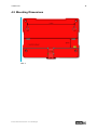
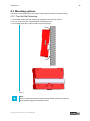
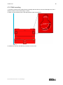
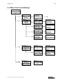
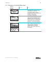
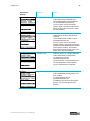
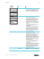
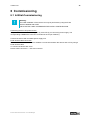
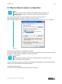
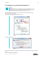
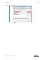
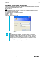
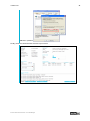
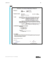
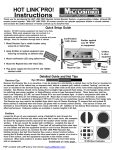
1
Version 3.0 User Manual IT-Infrastructure IF1000 series IF1000 series 1 Index 1 Remarks 3 1.1 1.2 1.3 1.4 1.5 1.6 3 3 3 3 3 4 Relevant Documentation for this device Used Symbol Explanation Data, Figures, Modifications Trademarks Copyright Standards 2 Notes on Operation & Safety 5 2.1 2.2 2.3 2.4 5 6 6 6 Safety Instructions Operation Location Damage Caused By Improper Use Warranty / Repair 3 Introduction 7 3.1 3.2 3.3 3.4 3.5 3.6 3.7 3.8 3.9 7 7 7 7 7 8 8 8 9 Cut & Stop Alarming Eventlog Display / Keypad Managed Switch Service Equipment Versions Scope of Delivery Environmental Conditions 4 Mounting 10 4.1 External Device Dimensions 4.2 Mounting Dimensions 4.3 Mounting options 4.3.1 Top Hat Rail Mounting 4.3.2 Wall mounting 10 11 12 12 13 © ads-tec GmbH • Heinrich-Hertz-Str. 1 • D-72622 Nürtingen IF1000 series 2 5 Systemfeatures 14 5.1 Frontpanel Operation Keys 5.1.1 Example configuration IP-Adresss and Contactname 5.2 LC-Display 5.3 Menu-Overview Settings 5.3.1 Description of individual Menu items 5.4 Menu-Overview Status 5.4.1 Description of individual menu items 5.5 Operational LED Status Display 5.5.1 Power Supply / Cut & Alarm / LAN-IN 5.5.2 LAN-OUT 5.6 Operational LED Status Displays 5.6.1 Status Display Activities when Booting 5.6.2 Status display activities when resetting to default settings 5.6.3 Status display activities with Firmware Updates 5.7 Interface Overview 5.7.1 Power Supply 24 VDC / BackUp 5.7.2 CUT & ALARM 5.7.3 Power Supply LAN-in (RJ45) / PoE (IEEE 802.AF) 5.7.4 LWL Fibre Optic 5.7.5 Serial Interface COM (RS232) 5.7.6 SMARTCARD READER NACH ISO 7816 14 16 19 20 21 25 26 29 29 31 32 32 32 32 33 33 34 34 34 35 35 6 Commissioning 36 6.1 6.2 6.3 6.4 36 37 38 40 Inititial-Commissioning Manual Network adapter configuration Settings for use with Internet Explorer 8 Calling up the Device Web Interface 7 Technical Details 42 8 Service & Support 43 8.1 8.2 43 43 ads-tec Support Company adress 9 Declaration of CE-Conformity © ads-tec GmbH • Heinrich-Hertz-Str. 1 • D-72622 Nürtingen 44 IF1000 series 3 1 Remarks 1.1 Relevant Documentation for this device The following documents are essential for setting up and operating this device: User Manual (This Documentation): Contains information for installation, commissioning and operating the device along with technical data of the device hardware. Qucik Start Guide: Quick Install Guide for fast commissioning. 1.2 Used Symbol Explanation Warning: The "Warning" symbol refers to activities which might cause personal injury or damage to the hardware or software! Note: The "Note" symbol familiarises you with conditions to be observed in order to ensure flawless operation. Additionally, hints and advice are given for a more efficient use of the device and for software optimisation. 1.3 Data, Figures, Modifications All texts, data and figures are non-binding. We reserve the right of modification in accordance with technological progress. At that point in time when the products leave our premises, they comply with all currently applicable legal requirements and regulations. The operator/operating company is independently responsible for compliance with and observance of any subsequently introduced technical innovations and new legal requirements, as well as for all usual obligations of the operator/operating company. 1.4 Trademarks It is hereby notified that any software and/or hardware trademarks further to any company brand names as mentioned in this User’s Guide are all strictly subject to the various trademark, brand name and patent protection rights. Windows®, Windows® CE are registered trademarks of Microsoft Corp. Intel®, Pentium®, Atom™ , Core™2 are registered trademarks of Intel Corp. IBM®, PS/2® and VGA® are registered trademarks of IBM Corp. CompactFlash™ and CF™ are registered trademarks of SanDisk Corp. RITTAL® is a registered trademark of the Rittal Werk Rudolf Loh GmbH & Co. KG. Any further additional trademarks and/or brand names herein, be they domestic or international, are hereby duly acknowledged. 1.5 Copyright This manual, including all contained figures, is protected by copyright law. Any use for third parties noncompliant with the copyright provisions is prohibited. Any reproduction, translation as well as electronic and photographic archiving and modification shall only be permitted after explicit written authorisation by ads-tec GmbH. Any party in violation of this provision shall be obliged to damage compensation. © ads-tec GmbH • Heinrich-Hertz-Str. 1 • D-72622 Nürtingen IF1000 series 4 1.6 Standards This device complies with the requirements and protective aims of the following EC regulations: Standards This device meets the test requirements for granting the CE sign according to the European test standards EN 61000-6-4 and EN 61000-6-2 This device complies with the test requirements in accordance with EN 60950 (VDE0805, IEC950) "Safety of Information Technology Equipment" The device meets the EN 60068-2-6 test requirements (sinus excitation). This device meets the EN 60068-2-27 test requirements (shock resistance test) Note: A respective conformity declaration for the authority in charge is available at the manufacturer and may be viewed on request. All connected components, as well as cable connections must also meet these requirements for compliance with the EMC legislation. For this reason, screened bus and LAN cables including screened connectors must be used and installed according to the instructions in this user manual. © ads-tec GmbH • Heinrich-Hertz-Str. 1 • D-72622 Nürtingen IF1000 series 5 2 Notes on Operation & Safety The unit operates under electrical tension and implements supersensitive component parts. Intervention by the User is required only for power supply line connection operations. Should any further alterations be required, it is necessary to consult either with the Manufacturer directly or with authorised service personnel accordingly. During said connection operations, the unit must be completely powered down. Specific requirements need to be met concerning the prevention of electrostatic discharge on component construction parts during contact. If the unit is opened up by a non authorised individual, the User may be subject to potential hazards and, warranty conditions are terminated. General Instructions This User’s Guide must be read and understood by all User’s and must be available for consultation at all times Assembly, operation start-up and unit operation must only be conducted by appropriately qualified and trained personnel All individuals and operators using the unit must strictly observe all safety and use instructions as provided within the User’s Guide All regulations and prescriptions on accident prevention and safety in force c/o the unit installation site must be strictly observed at all times This User’s Guide provides all the most important directions as required for safe and security oriented operation Safe and optimised unit operations are subject to appropriate storage, proper transport and handling, accurate unit setup, start-up and operation Note: Only the ads-tec original firmware / software is allowed for any of the adjustments and features described in this User’s Guide. Deployment of any firmware / software that has not been released by ads-tec will terminate all warranty conditions. 2.1 Safety Instructions Warning: For the prevention of possible unit damages, all cable lines (power supply, interface cables) must be hooked up strictly with the unit in power-OFF conditions. Warning: All unit assembly operations must be strictly conducted only under safe, secure and zero-potential conditions. Note: When handling parts and components susceptible to electrical discharge, please accurately observe all the relevant safety provisions (DIN EN 61340-5-1 / DIN EN 61340-5-2) © ads-tec GmbH • Heinrich-Hertz-Str. 1 • D-72622 Nürtingen IF1000 series 6 2.2 Operation Location This device is designed for use in industry. You must ensure compliance with the specified environmental conditions. Using the device in non-specified environments, e.g. on board ship or in areas containing explosive vapours, gases or gas mixes, as well as in extreme heights, is prohibited Warning: For the prevention of water condensate accumulation, the unit should be turned ON only when it reaches ambient temperature. This particularly applies when the unit is subject to extreme temperature fluctuations and/or variations. Avoid overheating during unit operations; the unit must not be exposed to direct sunlight or any other direct light or heat sources. 2.3 Damage Caused By Improper Use This device must immediately be shut down and protected from any accidental commissioning if the operating system shows any obvious damage caused by, for example, improper operating or storage conditions, or by improper use or handling. 2.4 Warranty / Repair During the warranty period, any repair must only be carried out by the manufacturer or by a person authorised by the manufacturer. © ads-tec GmbH • Heinrich-Hertz-Str. 1 • D-72622 Nürtingen IF1000 series 7 3 Introduction The Industrial Firewall constitutes a link between the IT world and automation, thereby meeting the requirements of IT security as well as those by the production line maintenance personnel. It enables monitoring and control of the plant setup network, and of the relative access points. Its essential security protection mechanism is constituted by the event-dependent and physical network separation. This Firewall furthermore offers, amongst others, a secure access in the event of service operations; it enables traffic shaping and is capable of implementing the available virus scanners. Note: For the efficient online configuration of your ads-tec devices, it is possible to download the current version of the free tool „IDA light" on the company`s homepage http://www.ads-tec.de. The tool offers you for example the possibility of defining individual parameters or whole groups of parameters at a Server device and to transfer your settings to a limited selection and/or to all ads-tec devices of same design and version, without having to make these configurations timeconsuming at each individual device. You also have the possibility of assigning sequential IP addresses for your ads-tec devices. With IDA light you can comfortably provide own groups of parameters according to your specific requirements and modify them at any time. 3.1 Cut & Stop During critical start-up or production phases, the Ethernet uplink can be physically disconnected i.e. via hardware, through a 24 V input. This will safely rule out both intentional and unintentional external manipulation. The uplink is reconnected through the same input. This function makes integration into an automation concept very simple. 3.2 Alarming In the event that a rule is violated, the alarm signal is reported to the control centre through an output. Necessary measures can be automated directly. For example, acoustic indicator lights can signal the alarm condition. E-mails can be sent out automatically to signal a rules violation event. 3.3 Eventlog A zero-voltage event logbook with retentive memory stores all events whenever the firewall is disconnected from the power supply (NV-RAM option). The event logbook can be read out either locally or via a central Syslog server. 3.4 Display / Keypad The built-in display can be used to configure the essential unit functions.It is thus possible to obtain a quick system analysis, e.g. of the network load, directly from the display. The display and keys can be password-protected against unauthorized manipulation 3.5 Managed Switch Network segments can be set up without any additional hardware by using the managed switch integrated into the firewall. It is possible to connect multiple systems or terminals up to one Firewall. Each port can be switched off individually to prevent unauthorized data traffic monitoring. © ads-tec GmbH • Heinrich-Hertz-Str. 1 • D-72622 Nürtingen IF1000 series 8 3.6 Service Service access via a secure service port. Connecting the Firewall to an analogue, ISDN or GPRS modem for dial-in access provides for affordable remote maintenance, even without an Internet connection. 3.7 Equipment Versions The device is available in 4 configuration versions: Ausstattungsvariante IF1100 IF1110 IF1200 IF1210 LAN-in RJ45 RJ45 LWL LWL LAN-out RJ45 RJ45 RJ45 RJ45 NVRAM - X - X RJ45 (Registered Jack 45 = standardized jack) provided per an Ethernet standard as frequently implemented in telecom applications. The transmission method is equivalent to 10/100Mbits half and full DUPLEX 100 BASE-TX. LWL (fibre optic connection) are flexible optic media for controlled conduction of light. Contrarily to the Ethernet standard, the fibre optic connection technology is insensitive to voltage interference. The plugs required for implementation are equivalent to the MTRJ Standard Multimode with a 100BaseFX 100 Mbit⁄s Ethernet transmission method via fibre optics. NVRAM (non-volatile RAM = non-volatile Random Access Memory) is an electronic memory storage technology whereby data is stored even without maintenance of power supply. Note: The LAN-in interface can be equipped with an RJ45 or with an LWL fibre optic connection, as the case may be. 3.8 Scope of Delivery Please check supply package contents for integrity and completeness: Scope of Delivery IF1000 series 1 x Industrial Firewall 2 x 2 pole Plug 1 x 4 pole.Plug Ethernetcable 1m Quick Guide Inbetriebnahme / Quick Guide Montage GNU General Public License Service-CD © ads-tec GmbH • Heinrich-Hertz-Str. 1 • D-72622 Nürtingen IF1000 series 9 3.9 Environmental Conditions The unit can be put into operation and used under the following conditions. Failure to observe any one of the specified data will immediately terminate all warranty conditions. ads-tec cannot be held liable for any damages arising due to improper device or unit use and handling. Permissible ambient temperatue during operation 5 … 60° C during operation (UL) 5 … 50° C during storage -20 … 50° C Humidity during operation during storage Vibration during operation Shock During operation 10 … 85% without condensate 10 … 85% without condensate 1 G, 10 … 500 Hz (DIN EN 60068-2-6) 5 G, with half-wave of 30 ms (DIN EN 60068-2-29) Note: For Use In Pollution Degree 2 Environment Only Type 1 “indoor use only”. © ads-tec GmbH • Heinrich-Hertz-Str. 1 • D-72622 Nürtingen IF1000 series 10 4 Mounting 4.1 External Device Dimensions Abb. 1: © ads-tec GmbH • Heinrich-Hertz-Str. 1 • D-72622 Nürtingen IF1000 series 11 4.2 Mounting Dimensions Abb. 2: © ads-tec GmbH • Heinrich-Hertz-Str. 1 • D-72622 Nürtingen IF1000 series 12 4.3 Mounting options The device unit is designed for both top hat rail mounting as well as for wall-mounting. 4.3.1 Top Hat Rail Mounting 1. The Firewall must be placed obliquely up against the top of the top hat rail. 2. Fix it on by pressing the underside lightly up against the rail. 3. The Firewall must firmly snap into place on the top hat rail. Abb. 3: Note: Check to make sure that the Firewall will not detach itself from the top hat rail by lightly tugging the underside forward. © ads-tec GmbH • Heinrich-Hertz-Str. 1 • D-72622 Nürtingen IF1000 series 4.3.2 Wall mounting 1. Provide for screws on the relative device mounting wall so that they are set horizontally level, with a distance between screws amounting to 170mm. 2. Attach on the Firewall by way of the appropriate cavities as illustrated. Abb. 4: To release the unit from the DIN rail, proceed in reverse order. © ads-tec GmbH • Heinrich-Hertz-Str. 1 • D-72622 Nürtingen 13 IF1000 series 14 5 Systemfeatures 5.1 Frontpanel Operation Keys The device is provided with operation keys for navigation and unit configuration via the LCD menus. Said LCD menus are easily accessed via simple operation of the ESC or the ENTER keys. You will find a description of the single menu items in the following LC display section. The front panel operation keys are provided with the following functions: Symbol Navigation function Configuration function Press to exit the current menu level. (ESC)) If the input mode is activated, the variation can be overruled/abandoned by pressing ESC. Press to access a menu level or to confirm a change entry. (ENTER) To enter or to change data, the input mode must first be activated by pressing ENTER. This will have only one digit flashing. To adopt the change entries, the input mode must first be deactivated by pressing ENTER. This will highlight the whole line. For selection amongst a number of options, selection is activated via this key. selection of either German or English from the available language options). Menu navigation direction arrow (UP) For selection amongst a number of options, the UP key will access and highlight the selection item in ascending/up order (e.g. selection of either German or English from the available language options). Upon entry or change of various data, the highlighted digit can be accessed and changed in ascending/up direction. The succession of the characters is provided in the ASCII code. However, a space character is assigned for simplification of first-time operation of the DOWN navigation direction option. If the key is pressed a second time, the system proceeds with ASCII character strings. © ads-tec GmbH • Heinrich-Hertz-Str. 1 • D-72622 Nürtingen IF1000 series 15 Menu navigation direction arrow (LEFT) If the input mode is activated, each digit is marked and can be changed via access with the UP and DOWN arrow keys. Menu navigation direction arrow (DOWN) For selection amongst a number of options, the DOWN key will access and highlight the selection item in ascending/up order (e.g. selection of either German or English from the available language options). Upon entry or change of various data, the highlighted digit can be accessed and changed in ascending/up direction. The succession of the characters is provided in the ASCII code. However, a space character is assigned for simplification of first-time operation of the DOWN navigation direction option. If the key is pressed a second time, the system proceeds with ASCII character strings. Menu navigation direction arrow (RIGHT) If the input mode is activated, each digit is marked and can be changed via access with the UP and DOWN arrow keys. Note: To carry out changes in the LCD menus, the following character set is available. © ads-tec GmbH • Heinrich-Hertz-Str. 1 • D-72622 Nürtingen IF1000 series 16 5.1.1 Example configuration IP-Adresss and Contactname IP-Adress Default IP address 192.168.0.254 needs to be changed into 192.168.1.250 whilst the subnet mask must be changed from 255.255.255.0 into 255.255.52.0. The IP address is highlighted and the input window is deactivated. To change the IP, proceed as follows: Menu Action Press ENTER to activate the iput mode. -> The input focus will be active on the first digit. Press the RIGHT direction arrow key eight times -> The input focus will be active on the 0 Press the UP direction arrow key once. -> Change to 1 Press the RIGHT direction arrow key three times -> The input focus will be active on the 4 Press the DOWN direction arrow key four times -> Change to 0 Now press ENTER to confirm all the changes to the first line in the input mode. -> The overall IP is highlighted The text message “Please wait” will come up on display whilst the data is being stored. If the input mode is exited by pressing ESC, the changes are overruled/ abandoned. Press the DOWN direction arrow key once -> The subnet mask is highlighted Press ENTER to activate the iput mode. -> The input focus will be active on the first digit. Press the RIGHT direction arrow key six times -> The input focus will be active on the 2 © ads-tec GmbH • Heinrich-Hertz-Str. 1 • D-72622 Nürtingen IF1000 series 17 Press the DOWN direction arrow key twice -> Change on the space Press the RIGHT direction arrow key twice -> The input focus will be active on the 5 Press the DOWN direction arrow key three times -> Change to 2 Now press ENTER to confirm all the changes to the first line in the input mode. -> The overall IP is highlighted The text message “Please wait” will come up on display whilst the data is being stored. If the input mode is exited by pressing ESC, the changes are overruled/ abandoned. Press the ESC key to exit this menu. All the changes entered have been duly stored. © ads-tec GmbH • Heinrich-Hertz-Str. 1 • D-72622 Nürtingen IF1000 series 18 Contact name Contact name Mr. Miller must be changed to Ms. Miller.. The Contact Name is highlighted and the input window is deactivated. To change the Contact Name, following steps are required:: Menu Action Press ENTER to activate the iput mode. -> The input focus will be active on the first digit. Press the RIGHT direction arrow key once. -> The input focus will be active on the r Press the UP direction arrow key once. -> Change to s Now press ENTER to confirm all the changes to the first line in the input mode. -> The overall Contact Name is highlighted The text message “Please wait” will come up on display whilst the data is being stored. If the input mode is exited by pressing ESC, the changes are overruled/ abandoned. Press the ESC key to exit this menu. All the changes entered have been duly stored. © ads-tec GmbH • Heinrich-Hertz-Str. 1 • D-72622 Nürtingen IF1000 series 19 5.2 LC-Display The device is fitted with an LCD which allows direct access to configuration settings. Any modifications to the firewall and web interface settings made via the LCD menu will take effect immediately. Furthermore, the display shows event messages and status information for quick on-site system analysis. The LCD menu option Lock can be used to lock the display and all front panel keys. When these are locked, the device PIN is required to access and/or modify any device information. Hence, the Lock function protects the device against unauthorised on-site modifications. The LCD menu can be accessed by pressing the ESC or ENTER key. The LCD menu contains the following main menu items: Settings Allows configuration of basic Firewall settings, which includes locking the display and all front panel keys. Also allows setting the local IP address as well as the display language and various system information Status Shows all current event log entries and device information. Also allows initiating a self test of the following components: display, front panel keys, CUT and ALARM function.The connection control displays the state of the Service, Open VPN and IPsec connections.. Note: The default language setting is English. In order to select a different language, open the main menu and select the following menu items: Settings/ LCD menu/ Language Confirm your selection by pressing ENTER. (Selection will be marked by an X.) Then leave the menu by pressing ESC. © ads-tec GmbH • Heinrich-Hertz-Str. 1 • D-72622 Nürtingen IF1000 series 5.3 Menu-Overview Settings © ads-tec GmbH • Heinrich-Hertz-Str. 1 • D-72622 Nürtingen 20 IF1000 series 21 5.3.1 Description of individual Menu items Network Anzeige © ads-tec GmbH • Heinrich-Hertz-Str. 1 • D-72622 Nürtingen Selection Action Transbridge The network mask allows setting the operational mode. Additional options are available for each mode. In Transparent Bridge mode, the Firewall acts as a Layer 2 Bridge and is invisible to all participants. Transbridge= LAN Settings IP-Router The Firewall treats the networks at the LAN-In and LAN-Out interfaces as two separate networks and filters these separately. Hence, this mode requires that two independent IP addresses be configured for LAN-In and LAN-Out. IP-Router = LAN-In/LAN-Out Settings.. LAN-Einstellungen Depending on the selected operational mode, IP address assignment can be configured under LAN Settings. Available options are: Static IP address, DHCP, DHCP fallback and PPPoE/DHCP. IF1000 series 22 Systeminfo Display © ads-tec GmbH • Heinrich-Hertz-Str. 1 • D-72622 Nürtingen Selection Action System name This name serves as a unique identifier of the device at its installation site. The Firewall system name displayed can be specified/changed here. You may freely choose a Firewall system name. The name entered here will be shown in the LCD menu and in the web interface. System location This item serves as a unique identifier of the location at which the device is operated. The Firewall system location can be specified/changed here. You may freely choose a Firewall system location. Specifying the system location provides additional information on the device location. The location entered here will be shown in the LCD menu and in the web interface. Contact name This item serves as a unique identifier of the responsible contact person. A contact name can be specified/changed here. You may specify a contact person that can be contacted in case problems occur or maintenance is required. Contact location This item serves as a unique identifier of the responsible contact person and their location. A contact location can be specified/changed here. In addition to the name of the contact person, you may also specify their location. IF1000 series 23 LCD-Menu Language © ads-tec GmbH • Heinrich-Hertz-Str. 1 • D-72622 Nürtingen Selection Action Deutsch/Englisch Two language options are available. Changing the language setting here will also affect the language of the web interface. The default setting is English. Display & Keys The display and keys can be locked to prevent unauthorised access. When locked, the display will not show any information and the keys can no longer be used to modify the device configuration. The only operation possible in locked mode is entering the required PIN for unlocking the display and keys. The lock will only become active once the user exits the LCD menu by pressing ESC. The PIN needs to be entered correctly in order for all LCD menu functions to become accessible again. When the Firewall is turned off and on again, the lock will still be active and the PIN needs to be re-entered. Keys only This option allows locking the keys separately from the display. With locked keys, the LCD menu can no longer be used to modify the device configuration. The LC display will, however, still show current network load and other system information. The only operation possible in locked mode is entering the required PIN for unlocking the display and keys. The lock will only become active once the user exits the LCD menu by pressing ESC. The PIN needs to be entered correctly in order for all LCD menu functions to become accessible again. When the Firewall is turned off and on again, the lock will still be active and the PIN needs to be re-entered. Unlocked By default, neither keys nor display are locked. IF1000 series 24 Reboot Display New PIN In order to change the PIN, the old PIN needs to be entered. The PIN may be changed independently from the web interface password. The default PIN is empty; any user-defined PIN may be up to 14 digits long. Selection Action The reboot option allows re-starting the Firewall via the LCD menu. Confirm selection of this option by pressing the down key . © ads-tec GmbH • Heinrich-Hertz-Str. 1 • D-72622 Nürtingen IF1000 series 5.4 Menu-Overview Status © ads-tec GmbH • Heinrich-Hertz-Str. 1 • D-72622 Nürtingen 25 IF1000 series 26 5.4.1 Description of individual menu items Events Anzeige Connections Service © ads-tec GmbH • Heinrich-Hertz-Str. 1 • D-72622 Nürtingen Selection Action Event log The event log allows retracing system messages and alarms. Select individual log entries using the UP and DOWN keys. The event log display is comparable to a transcript of messages. Use the Event log menu to view any logged events. Melssage Ack. Use the Message Acknowledgement option to override or end, respectively, any events logged in the event log. Manually acknowledging event messages will end all active events. In automatic setting, events will be acknowledged automatically after a predefined period of time. Selection Action Service Anhand des Service Menüpunktes kann der Status einer Service Verbindung überprüft, bzw. nachvollzogen werden. Wenn die Schnittstelleerfolgreich verbunden ist, wird der Status connected angezeigt. Bei einer inaktiven Verbindung wird disconnected angezeigt. OpenVPN Use the menu item OpenVPN to display all active VPN connections. Settings can be changed directly via the LCD menu. IPsec Use the menu item IPsec to display all IPsec-related information and settings. The display screen can be used to monitor the IPsec status. Settings can be changed directly via the LCD menu. IF1000 series 27 Device info Anzeige Device Test Anzeige © ads-tec GmbH • Heinrich-Hertz-Str. 1 • D-72622 Nürtingen Selection Action Device info This option displays general device information. The screen shows the name of the manufacturer, the device variant, whether a NVRAM card is installed, the current firmware version, and the current firmware build. Selction Action Screen Starts the display test. Press Enter to start the display test. Perform this test to check the display for correct functioning. You can visually check whether all characters are displayed properly on the display. Four different test screens will appear, each of which will need to be confirmed by pressing any front panel key. When the test is finished, you will automatically be taken back to the menu view. Keys Starts the key test. Press Enter to start the key test. Perform this test to check the keys for correct functioning. You will be prompted to press specific keys, whereupon you should press the respective key. In case one key is defective, you may exit the test using the other keys. When the test is finished, you will automatically be taken back to the menu view. Alarm Sets the alarm output. Sets the alarm output and turns on the alarm LED. The letters AL will appear in the upper right corner of the display, indicating that an alarm was triggered. AL will continue to flash until the alarm is either switched off or acknowledged automatically. Perform this test to check the alarm output for correct functioning. IF1000 series © ads-tec GmbH • Heinrich-Hertz-Str. 1 • D-72622 Nürtingen 28 Internal Cut Sets the internal CUT. Sets the CUT and turns on the CUT LED. The letters INT will appear in the upper right corner of the display, indicating that an internal CUT was triggered. INT will continue to flash until the internal CUT is either switched off or acknowledged automatically. Perform this test to check the internal CUT for correct functioning. Ping-Test With the aid of the PING-Test, the accessibility of an affiliated remote station is tested. The PING-Test sends an echo request packet to the destination address of the remote station to be tested and then proceeds with test information assessment. Enter the destination address that needs to be tested in IP address form in the appropriate entry field. It is furthermore necessary to enter the packet quantity required to be sent. Said quantity is limited to a maximum of 10 packets. IF1000 series 29 5.5 Operational LED Status Display The boot-up process starts as soon as the firewall is supplied with a voltage source. With the aid of the Lan-in LEDs it is possible to check whether the Firewall is booting up as well. The table herunder provides boot-up process LED blink frequency via which it is possible to check that the device is booting up correctly. In the example, no LAN-in cable / PoE is connected up. The minute the traffic display comes up on the LCD, the boot up process has been successfully concluded. State of theLED representation aus grün grün blinkend rot orange orange blinkend 5.5.1 Power Supply / Cut & Alarm / LAN-IN Abb. 5: POWER Signal Action L+ The device is not supplied with a power. L+ The device is provided with voltage via POWER and is ready for operation. BACKUP Signal Action The device is not supplied with a backup power. The device is provided with voltage via POWER and is ready for operation. © ads-tec GmbH • Heinrich-Hertz-Str. 1 • D-72622 Nürtingen IF1000 series 30 CUT & ALARM Signal Action L+ CUT & ALARM interface is not supplied with a voltage. The CUT & Alarm functionality is not available. L+ CUT & ALARM interface is supplied with a voltage. The CUT & Alarm functionality is given. INT An internal Cut is triggered EXT An external Cut is triggered AL An Alarm is triggered LAN-IN Signal Action PoE The device is not supplied with a power. PoE The device is provided with voltage via PoE and is ready for operation. LINK The interface is connected to a remote station and is ready for operation. ACT Displays the traffic between the firewall and remote. © ads-tec GmbH • Heinrich-Hertz-Str. 1 • D-72622 Nürtingen IF1000 series 31 5.5.2 LAN-OUT Abb. 6: LAN-OUT Signal Action LINK The interface is connected to a remote station and is ready for operation. ACT Displays the traffic between the firewall and remote. © ads-tec GmbH • Heinrich-Hertz-Str. 1 • D-72622 Nürtingen IF1000 series 32 5.6 Operational LED Status Displays 5.6.1 Status Display Activities when Booting Te boot-up process starts as soon as the firewall is supplied with a voltage source. With the aid of the Lan-in LEDs it is possible to check whether the Firewall is booting up as well. 5.6.2 Status display activities when resetting to default settings Via the Factory Default keys on the rear side of the Firewall it is possible to reset the Firewall back to its default factory settings at any time, independently of its configuration. To set the Firewall back to its default settings, the factory default keys must be pressed during current operations. In the example, no LAN-in cable / PoE is connected up. The factory default keys must be pressed once, briefly in order to start the set-back to default settings process 5.6.3 Status display activities with Firmware Updates A firmware update can be made by using the web interface. The actual process of updating might take a few minutes. © ads-tec GmbH • Heinrich-Hertz-Str. 1 • D-72622 Nürtingen IF1000 series 33 5.7 Interface Overview Abb. 7: The device has the following interfaces (front): 1. 2. 3. 4. 5. 6. Power 24V DC voltage supply (2 pole COMBICON plug) Backup 24V DC BACKUP voltage supply (2 pole COMBICON plug) CUT& ALARM plug (4 pole COMBICON plug) LAN-in with RJ45 (PoE) or LWL fibre optic connection 9 pole SUB-D connector / RS232 LAN-out with 4x RJ45 connection Note: All input voltages can be hooked up redundantly (Power, Backup and PoE via LAN-in). 5.7.1 Power Supply 24 VDC / BackUp The supply voltage implements a lead-through terminal with screw connection (the illustration shows the jack provided in the device)) Pin-Number Signal-Name 1 24V DC 2 0 V DC PIN 1: = L+ 24V DC Power Supply PIN 2: = GND Ground © ads-tec GmbH • Heinrich-Hertz-Str. 1 • D-72622 Nürtingen IF1000 series 34 5.7.2 CUT & ALARM Pin-Number Signal-Name 1 TX + 2 TX - 3 RX + 4 NC PIN 1: = L+ PIN 2: = GND PIN 3: = CUT PIN 4: = AL users 24V DC feed-in of the alarm output voltage Ground feed-in of the alarm output voltage 24V DC feed-in of an external switching signal (galvanically isolated) 24V DC ALARM output (galvanically isolated) alarm out put for signalling to external 5.7.3 Power Supply LAN-in (RJ45) / PoE (IEEE 802.AF) Pin-Number Signal-Name 1 TX + 2 TX - 3 RX + 4 PoE/G 5 PoE/G 6 RX - 7 PoE/-48V 8 PoE/-48V 5.7.4 LWL Fibre Optic An MTRJ fibre optic plug is implemented for the LWL fibre optic connection.62.5/125µm multimode cable from the MTRJ plug to the Duplex plug. © ads-tec GmbH • Heinrich-Hertz-Str. 1 • D-72622 Nürtingen IF1000 series 35 5.7.5 Serial Interface COM (RS232) 9 pole SUB-D connector RS232 for connection of an analogue, ISDN or GPRS standard modem unit Pin-Number Signal-Name 1 DCD 2 RxD 3 TxD 4 DTR 5 GND 6 DSR 7 RTS 8 CTS 9 RI 5.7.6 SMARTCARD READER NACH ISO 7816 The SIM card reader serves for the storage of the configuration data. Pin-Number Signal-Name 1 VCC 5 Volt 2 RESET 3 CLOCK 4 NC 5 GND 6 NC 7 I/O 8 NC © ads-tec GmbH • Heinrich-Hertz-Str. 1 • D-72622 Nürtingen IF1000 series 36 6 Commissioning 6.1 Inititial-Commissioning Achtung: The initial installation of this device can only be performed by using the RJ45 interface labelled with HOST. A RJ45 PATCH CABLE IS REQUIRED FOR INITIAL CONFIGURATION. Connecting the 24 V DC power source The power for this device can be supplied by a 24V DC (2-pin connector) power supply. The corresponding COMBICON connector is included in the scope of delivery. Connect the device with a suitable power supply unit. RJ45 network cable connection For initial installation it is essential to establish a connection between this device and a PC by using a RJ45 network cable. To connect the device with a PC: Device HOST connector <-> PC LAN connector © ads-tec GmbH • Heinrich-Hertz-Str. 1 • D-72622 Nürtingen IF1000 series 37 6.2 Manual Network adapter configuration Note: The notes below have been created by using Windows XP®. Should you use a different operating system, the directory paths and properties described here might vary. Open the Properties tab of the network adapter you are using. The directory path is: Start> Settings> Network connections> LAN connections> Properties. Select the following option in the pop-up dialogue: Internet protocol (TCP/IP); then click on Properties . Abb. 8: Here select the following item: Use following IP address Access to the device will only be enabled once the following parameters have been entered as the fixed IP address, or if the computer is located in the same subnet area: IP Address: 192.168.0.100 Note: (The last section of digits must represent a number between 1 and 253; the value " 100" was selected in the example) Once the IP address is entered, you have to input the Subnet mask address. If you click into the Subnet mask box, the correct address is automatically entered. Subnet Mask: 255.255.255.0 You can now close the dialogue boxes by pushing the "OK" button. © ads-tec GmbH • Heinrich-Hertz-Str. 1 • D-72622 Nürtingen IF1000 series 38 6.3 Settings for use with Internet Explorer 8 Warning: If Internet Explorer 8 is used, issues with the web interface might occur. If you experience any problems, the IP address of the device must be entered in the Local Intranet list in order to display the web interface correctly. Open Internet Explorer and navigate to the Security tab with the following directory path: ToolsInternet optionsSecurity Switch to the Local Intranet tab and click there on Sites.. Abb. 9: Then click on Advanced. Abb. 10: In the Add this website to the zone address line, enter the device IP address and confirm this step with Add. Default IP address: http://192.168.0.254 © ads-tec GmbH • Heinrich-Hertz-Str. 1 • D-72622 Nürtingen IF1000 series 39 The entered IP address should now appear in the list under Websites. Abb. 11: © ads-tec GmbH • Heinrich-Hertz-Str. 1 • D-72622 Nürtingen IF1000 series 40 6.4 Calling up the Device Web Interface To access and open the device web interface, start up your web browser. In the browser’s address bar, enter the following IP address then confirm with Enter http://192.168.0.254 Login Once the IP address has been entered with success, the login prompt appears. In the login prompt, entry of the default settings is required. The default configuration in just-delivered conditions is: User Name : admin Password : admin Confirm your entries by clicking on: OK Abb. 12: Note: If the login prompt does not appear, check to ensure that the device has been connected via a RJ45/LWL optic fibre connection cable. Otherwise, connect the device up to a PC (Device LAN-in/LAN-out connection <> PC LAN connection). If there still is no connection to the firewall login prompt, it is necessary to check the proxy and local firewall settings. It often occurs that also local subnet addresses ( e.g. 192.168.x.x) are diverted to a proxy server. In this case it is possible to select the “Bypass proxy server for local addresses” option to enter the © ads-tec GmbH • Heinrich-Hertz-Str. 1 • D-72622 Nürtingen IF1000 series 41 address in question. Finally, the device web interface will come up on screen. Abb. 13: © ads-tec GmbH • Heinrich-Hertz-Str. 1 • D-72622 Nürtingen IF1000 series 42 7 Technical Details Device Data IF1000 series Operating System Embedded LinuX Configuration protocol http, https Power Supply 24V DC +/- 20%, redundant power Supply Interfaces 1 x CUT & ALARM 1 x LAN RJ45- Connection10/100/1000MBit/s Autocrossover 4 x LAN RJ45Connection10/100/1000MBit/s Autocrossover 1 x SUB-D RS232 External Device Dimensions 203 mm x 156mm x 35mm Weight ca. 1 kg Protection Class IP20 Max. Power consumption max.12 Watt (typ.)bei 24V DC Environmental temperature during operation during storage -0°C ... + 60°C 0°C ... + 50°C (UL) Note: Detailed information for the device, see our website http://www.ads-tec.de. © ads-tec GmbH • Heinrich-Hertz-Str. 1 • D-72622 Nürtingen IF1000 series 43 8 Service & Support The ads-tec company and their partner companies offer a comprehensive service and support to your customers providing a quick and professional support in case of any question with respect to ads-tec products and components. Since the devices from ads-tec company are also used by partner companies, these devices might be configured according to specific customer requirements. Should any question or issue with respect to specific configurations and software installations arise, it can only be resolved by the system manufacturer. For devices not directly purchased from ads-tec, we cannot be responsible for the support. In this case, the support is provided by our partner company. 8.1 ads-tec Support Das Support Team von ads-tec steht für Direktkunden von Montag bis Freitag von 8:30 bis 17:00 unter der unten genannten Telefonnummer zur Verfügung: Tel: +49 7022 2522-202 Fax: +49 7022 2522-2602 E-Mail: [email protected] 8.2 Company adress ads-tec GmbH Heinrich-Hertz-Str. 1 D-72622 Nürtingen Germany Phone: Fax: E-Mail: Home: +49 (0) 7022 2522-0 +49 (0) 7022 2522-400 [email protected] www.ads-tec.de © ads-tec GmbH • Heinrich-Hertz-Str. 1 • D-72622 Nürtingen IF1000 series 44 9 Declaration of CE-Conformity IF1100 © ads-tec GmbH • Heinrich-Hertz-Str. 1 • D-72622 Nürtingen IF1000 series 45 IF1110 © ads-tec GmbH • Heinrich-Hertz-Str. 1 • D-72622 Nürtingen