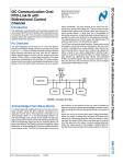
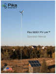
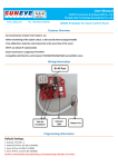
1
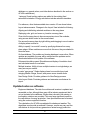
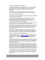
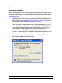
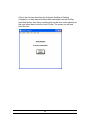
Solmetric PV Designer™ Software
TM
Solmetric PV Designer
User’s Guide
Version 4.50
Note: This Release of Solmetric PV Designer is available for free 30 day trial. In the free trial version,
all features of the software are enabled. Updated information as well as the software download and
release notes are available in the searchable Knowledge Base at www.solmetric.com.
SOLMETRIC SOLAR TEST AND MEASUREMENT EQUIPMENT
Solmetric PV Designer User’s Guide
Solmetric Corporation
www.solmetric.com
Phone 707-823-4600 • Fax 707-823-4620
Toll Free in US 877-263-5026
Document revision date: 4/4/2011
S O L M E T R I C
S U N E Y E
T M
U S E R ’ S
G U I D E
Limited Hardware and Software Warranty
This Solmetric software and the Solmetric SunEyeTM hardware (“Hardware”) are warranted
against defects in materials and workmanship for a period of one year when purchased in the
United States or two years when purchased outside the United States. During the warranty
period, Solmetric will, at its option, either repair or replace products which prove to be defective.
The warranty period begins on the date of shipment.
For warranty service or repair, this product must be returned to the appropriate authorized repair
center listed in the Solmetric SunEye User’s Guide. No returns will be accepted without an RMA
(obtain from Technical Support). For products returned for warranty service, the Buyer shall pay
for shipping charges to send the product to the repair center, and the repair center shall pay for
shipping charges to return the product to the Buyer. However, the Buyer shall pay all shipping
charges, duties, and taxes for products returned to the repair center from a country outside of the
United States.
The foregoing warranty shall not apply to defects resulting from improper or inadequate
maintenance by the Buyer, unauthorized modification or misuse, or operation outside of the
environmental specifications for the product. Unauthorized modification includes disassembly of
the Solmetric SunEye hardware, removal of any part of the Solmetric SunEye hardware,
modification to the operating system or operating system settings of the Solmetric SunEye, or the
installation of software on the device other than Solmetric SunEye software.
The design and construction of any system or building by the Buyer is the sole responsibility of
the Buyer. Solmetric does not warrant the Buyer’s system, products, or malfunction of the
Buyer’s system or products. In addition Solmetric does not warrant any damage that occurs as a
result of the Buyer’s system, product, or the Buyer’s use of Solmetric products.
To the extent permitted by applicable law, THE FOREGOING LIMITED WARRANTY IS IN LIEU
OF ALL OTHER WARRANTIES OR CONDITIONS, EXPRESS OR IMPLIED, AND WE
DISCLAIM ANY AND ALL IMPLIED WARRANTIES OR CONDITIONS, INCLUDING ANY
IMPLIED WARRANTY OF TITLE, NONINFRINGEMENT, MERCHANTABILITY OR FITNESS
FOR A PARTICULAR PURPOSE, regardless of whether we know or had reason to know of your
particular needs. No employee, agent, dealer or distributor of ours is authorized to modify this
limited warranty, nor to make any additional warranties.
SOME STATES OR COUNTRIES DO NOT ALLOW THE EXCLUSION OF IMPLIED
WARRANTIES, SO THE ABOVE EXCLUSION MAY NOT APPLY TO YOU. THIS WARRANTY
GIVES YOU SPECIFIC LEGAL RIGHTS, AND YOU MAY ALSO HAVE OTHER RIGHTS
WHICH VARY FROM STATE TO STATE OR COUNTRY TO COUNTRY.
ii
S O L M E T R I C
S U N E Y E
T M
U S E R ’ S
G U I D E
Limited Remedy
Our entire liability and your exclusive remedy shall be the replacement or repair of any Solmetric
hardware or software not meeting our Limited Hardware And Software Warranty which is
returned to an authorized repair center with a copy of your receipt.
IN NO EVENT WILL WE BE LIABLE TO YOU FOR ANY DAMAGES, INCLUDING ANY LOST
PROFITS, LOST SAVINGS, OR OTHER INCIDENTAL OR CONSEQUENTIAL DAMAGES
ARISING FROM THE USE OF OR THE INABILITY TO USE THE SOLMETRIC SOFTWARE
OR HARDWARE (EVEN IF WE OR AN AUTHORIZED DEALER OR DISTRIBUTOR HAS
BEEN ADVISED OF THE POSSIBILITY OF THESE DAMAGES), OR FOR ANY CLAIM BY
ANY OTHER PARTY.
SOME STATES OR COUNTRIES DO NOT ALLOW THE LIMITATION OR EXCLUSION OF
LIABILITY FOR INCIDENTAL OR CONSEQUENTIAL DAMAGES, SO THE ABOVE
LIMITATION MAY NOT APPLY TO YOU.
PLEASE CONTACT TECHNICAL SUPPORT BEFORE RETURNING ANY PRODUCT.
iii
S O L M E T R I C
S U N E Y E
T M
U S E R ’ S
G U I D E
Table of Contents
LIMITED HARDWARE AND SOFTWARE WARRANTY
LIMITED REMEDY
II
III
UNDERSTANDING THE SOLMETRIC PV DESIGNER
5
PV MODULE LAYOUT AND STRING DEFINITION
SHADE VISUALIZATION AND ANALYSIS USING SUNEYE DATA
AC KILOWATT-HOUR CALCULATIONS
DATA EXPORT AND SUMMARY REPORTS
5
6
6
7
SOLMETRIC PV DESIGNER VERSION 4.40
7
USING THE SOLMETRIC PV DESIGNER
11
INSTALLING THE SOFTWARE AND LOADING A SOLMETRIC SUNEYE SESSION
MINIMUM SYSTEM REQUIREMENTS:
INSTALLATION PROCEDURE
CREATING A DESIGN
INTERPRETING THE RESULTS
MANAGING FILES AND REPORTS
11
11
12
21
41
42
iv
1
Chapter
Understanding the Solmetric PV
Designer
The Solmetric PV Designer Software is a PC software application for calculating
energy production from a Photovoltaic (PV) solar electric system. The software is
intended as a tool for solar PV designers to perform high-level design and estimation.
It provides the following functionality:
PV module layout and string definition
Shade visualization and analysis using measured data from the Solmetric
SunEye™ shade analysis tool
Electrical AC kilowatt-hour calculations using local weather impacts and
site shading data.
Data export and summary reports
PV module layout and string definition
The Solmetric PV Designer™ enables the user to identify the placement of PV
modules on an array plane. This includes the following functions:
Definition of the parameters of the array plane, including tilt, azimuth, and
dimensions
Definition of arbitrary polygon array plane and display of the dimensions of
sides of the array plane and angles at each vertex (corner)
Retrieval of module dimensions from an extensive built-in database of
modules
Adding modules onto the array plane, move, and delete modules
Visualization of modules on the array plane
Selection of module and inverter type from a large built-in equipment
database with specifications, plus ability to enter custom specification for
equipment not included
5
Definition of up to ten (10) strings of modules, and association of modules
with strings
“Auto Layout” quick definition of multiple strings each with a given number
of modules, with selected horizontal and vertical spacing
Creating up to four designs or scenarios for side-by-side comparison
Shade visualization and analysis using SunEye data
The Solmetric PV Designer enhances the use of measured data from the Solmetric
SunEye to provide hourly, module level shading across the area of the array plane.
This includes the following capabilities:
Automatic import of Solmetric SunEye sessions and skylines
“Drag and drop” definition of skyline locations on the array plane
Hourly interpolation of the skylines data for each 1/3 module on the array
Shade contour plot showing annual insolation across the array plane with
color coding
AC kilowatt-hour calculations
The Solmetric PV Designer calculates and displays electrical AC kilowatt-hours using
local weather and site shade data. This includes the following:
Automatic retrieval of electrical characteristics of the modules and
inverters from the extensive built-in equipment database
Automatic retrieval of hourly weather data for irradiance and temperature
inputs to the array
Shade corrected computations, including impacts of string effects
Limit checking for string output voltage compatibility with inverter input at
minimum and maximum temperatures supplied by the user.
Side-by-side comparison of up to four (4) designs
Display annual, monthly, and average daily AC kWh production
Note: that AC kWh calculations in the unshaded case should agree closely
with PVWatts version 1.1. The following factors may cause differences
from PVWatts:
The following values are selected from the PV Designer equipment
database (vs. using general values)
Module specific power temperature coefficient
Module specific Nominal Operating Temperature (NOCT)
Module specific nominal power
6
Inverter maximum AC power
Inverter weighted efficiency
Shading data from the skylines is interpolated to obtain an hourly
shading probability across the array
Diffuse and direct radiation are considered separately in calculating the
effects of shading
Data export and summary reports
The Solmetric PV Designer enables data export and reports for use in
solar energy proposals or for further analysis. The following outputs are
available:
Export Design. Any design can be exported for storage or for sharing.
Each design can be imported by the same or different user at a later time.
Hourly CSV file (Comma Separated Values). Shows hourly AC kWh
production. Can be imported into Microsoft Excel or other programs for
further data analysis.
Summary pdf. Gives a summary of the design and the simulated monthly
AC kWh results for each design in the session.
Solmetric PV Designer Version 4.50
The following notes are intended to describe aspects of this software release.
What’s new in the latest release?
Release notes are available at www.solmetric.com. Version 4.50 adds the
following features to version 4.40 and below.
Arbitrary polygon (non-rectangular) roof shapes. User can
add/move/delete corners and define arbitrary polygon shape for array.
Trapezoids, triangles, and complex shapes can be defined.
Show Angles at each vertex of polygon roof area.
Show Distances for each side of polygon roof area.
"No-module" zones for on-roof obstructions. Rectangular or Ellipse shapes
defined on roof area to define keep-out zones. Used for visual reference
for on-roof obstructions, such as chimneys, roof vents, skylights, etc.
Locations and dimensions can be adjusted.
Simulation enhancements to include wind speed and more closely match
PV Watts on-line tool in the unshaded case. (Note: differences may be
observed since PV Designer uses specifications from the equipment
7
database vs. general values, and other factors described in the section on
AC kWh calculations.)
1-axis and 2-axis tracking options are added to the existing fixed
azimuth/tilt orientation. Energy calculations include selected orientation.
For reference, other features added since version 4.2 are shown below:
Layout enhancements. Changes to the Layout View include the following:
Aligning and distributing selected modules on the array plane.
Displaying ruler, grid, and cursor x-y location on array plane.
Zoom into the array plane to have more precise view of the modules,
using a zoom slider control or the mouse wheel.
Pan across the array plane by right-clicking and dragging to move location
of display when zoomed in.
Ability to specify “no-module” zones by specifying distance from array
plane edges. When modules are moved into this zone, they are shaded to
show the issue.
On-line database. The module and inverter database is now online. When
updates are available, the user will be notified and the updates can be
downloaded without a full update of the software.
Enhanced simulation speed. Simulations and display of insolation chart
and calculated results is now faster.
Multiple Inverters. Ability to have multiple inverters in a single design, as
many as one per module.
Inverter “gas gauge”. Single display shows how module layout and
stringing affects voltage, current, and power versus inverter limits.
New Design Guide. Provides guidance for New Design process.
Auto Layout Guide. Provides guidance and extensive new features for
layout.
Updated notes on software
Equipment database. The data for modules and inverters is updated and
accessible on-line, although there may still be industry equipment that is
not yet included in the database. Where data is known to be missing or
incomplete, notations are provided. This may have significant impact on
the calculations of energy production. User specifications can be entered
using the custom equipment function.
The calculations for AC kWh are adjusted for shade and weather. The
algorithms used provide an estimate. However, results may vary and the
calculations do not provide any guarantee of actual energy production.
8
Limit checks are performed on the designs:
The system operating voltage is checked to ensure it is in the operating
range of the inverter. The minimum voltage occurs at the maximum
temperature, and the maximum voltage occurs at the minimum
temperature.
The maximum open circuit voltage is checked to ensure it does not
exceed the maximum voltage of the inverter. The maximum voltage
occurs at the minimum temperature.
The maximum system current is checked to ensure it does not exceed the
maximum current of the inverter.
The worst case maximum system power (AC and DC) is checked to
ensure it does not exceed the maximum power of the inverter. It is
assumed that the worst case maximum system power occurs at the
maximum insolation and minimum temperature.
The Min/Max temperature values are defaulted to conservative values and
to be accurate must be reset by the user in the Weather Area.
Each design can have multiple inputs into multiple inverters. The design is
summarized in an expandable “tree” showing inverters, DC inputs, and
strings. Power from multiple inverters is summed in the kWh energy
production estimates.
Each design is limited to a single plane. It may be possible to simulate
multiple planes using the “Combine” feature which sums the energy from
up to four (4) designs. This assumes that each inverter input (MPPT) is
connected to modules that are in the same plane.
Solmetric SunEye sessions are required for operation of the software. An
example session is available at www.solmetric.com for illustration but
shade calculations can only be done using skylines from the Solmetric
SunEye.
Derating. Derate factors, such as wire losses and other factors that reduce
output are incorporated into each design. These values are defaulted and
to be changed must be input by the user for each design. Derate factors
are expressed in percent.
Language support. The Solmetric SunEye and the Desktop Companion
Software are available in five languages (English, French, Italian, German,
and Spanish). However, the newest features may be available in English
only, since the translations to non-English languages are normally one or
two revisions behind the English. Similarly, the non-English documentation
may be delayed by one to two revisions from the English documentation.
This PV Designer User’s Guide is currently in English only. Translation into
French, Italian, German, and Spanish are available, but are delayed by
one revision.
9
10
2
Chapter
Using the Solmetric PV Designer
The Solmetric PV Designer is designed to be easy to learn and easy to use, yet
powerful enough to provide accurate simulations in a wide variety of applications.
This section is an introduction to the basic functions of the software by illustrating a
typical design sequence.
This chapter includes the following sections:
Installing the Software and loading a Solmetric SunEye session
Creating a Design
Interpreting the Results
Managing files and reports
Installing the Software and loading a Solmetric SunEye
session
The Technology Preview of the Solmetric PV Designer Software is embedded within
Version 3.0 or higher of the Solmetric SunEye Desktop Companion Software. Please
refer to the Solmetric SunEye User’s Guide for more information about using your
Solmetric SunEyeTM and the Desktop Companion Software in general.
Minimum system requirements:
Operating System: Windows 7, Windows Vista, Windows XP SP2 or later
(Professional, Home, or Media Center)
Processor Speed: 1 GHz minimum
RAM: 1 GByte minimum, 2 GByte recommended
Available Disc Space: 200 MB or more.
MS Internet Explorer 7.0 or higher.
Display resolution: 1280x1024 or greater. The software will function with
lower resolution, such as 1024x800, although there may be some steps
required to see all design information.
11
Systems that do not meet these requirements may not operate correctly.
Installation Procedure
Ensure that the latest version of the Solmetric SunEye software is installed on your
computer. The software can be downloaded from the software downloads page at
www.solmetric.com.
While connected to the internet, navigate to the Software Download link on
the Solmetric website at www.solmetric.com/support-info.html. Click on the
link Download current software (eg. version 4.50.xxxx).
Note: If you have a new Solmetric SunEye, purchased after May 15, 2010,
you may already have the most current software version on the CD-ROM that
came with the Solmetric SunEye. Insert the CD-ROM into the CD drive on
your Windows desktop computer. If the welcome screen does not
automatically open, click Start then My Computer and double-click on the
CD drive. Then double-click on setup.exe. Always check to be sure it is the
latest version.
You may be asked to Run or Save the software. See below. Press Run, and
the software installation process will start.
12
Follow the on-screen instructions in the welcome screen to install the
Solmetric SunEye™ Desktop Companion Software and update the software
on the Solmetric SunEye TM device. If not already installed, the installation will
install Microsoft ActiveSync (for Windows) or Windows Mobile Device Center
(for Windows Vista) which is needed to communicate with the Solmetric
SunEyeTM device. Installation on the Solmetric SunEye device can be
skipped using the “Skip” selection on the installation dialog shown below.
13
If this is the first time launching the Solmetric SunEye TM Desktop
Companion, or there has never been data transferred from the SunEye
hand-held device, then there is nothing that can be done on the desktop at
this point other than to view the User’s Guide. The screen you will see
looks like this:
14
To use the PV Designer, a Solmetric SunEye session must be loaded into
the Desktop Software. To load a session, click Browse Sessions… and
navigate to the file location where sessions are stored, normally My
Documents/Solmetric/SunEye/Sessions/. Select the desired session. The
Session Properties dialog will appear, as shown below.
15
Launch the PV Designer Software by selecting the Session menu, then PV
Designer. The first time the software is run, the user will be presented with the
choices as shown in the screen below, including starting a free trial, or
ordering the software license. Once a free trial is initiated, the number of days
remaining will be displayed and when the trial is completed on that computer,
this option will no longer be available. Note that this trial or license is not
required for the SunEye Desktop software that is not PV Designer related.
16
Once the PV Designer is initiated, the initial software launch may take up to
10 seconds. The first time the PV Designer is launched for that session, it will
be blank, that is, it will contain no existing designs. The Session Guide will
appear to lead the user through the process of creating a design, as shown
below. Note: for best display results, maximize the PV Designer window to
view it full screen. You are ready to create a new design.
After a design is done, it will be associated with that session, and when the
PV Designer is launched again within that session, the previously stored
designs for that session will appear at startup.
17
When creating the first design in a session, you will see the PV Designer
Session Guide as shown below.
For each session you can create up to four designs. To create a design,
follow the steps at the left side in the Session Guide. After each step you
can select “Cancel”, “Previous”, “Next”, or “Finish”.
Weather – Choose an appropriate nearby weather station and enter
minimum and maximum temperatures for limit checking the design.
Weather data is applied to all designs in the session. Note that newly
selected weather stations will require the DVD or access to the Internet.
Min and Max temperatures can be found at www.weather.com.
Name and Equipment – Choose a name for the design and choose the
module and inverter models to be used in the design. Equipment can
optionally be selected or edited using the Auto Layout Wizard.
Define Layout Plane Area – Enter plane orientation and dimensions.
Create Array– Specify type and location of Modules on Layout Plane.
Choose the number of modules or kW peak, choose number of rows, and
justification (left-right/top-bottom).
Inverter Properties – Specify type of inverter and number of inverters in
design.
Note that all of the above design parameters can be changed outside the
PV Designer Guide in the regular PV Designer user interface, also
referred to as “Manual Mode”.
18
There are three types of guides in the PV Designer, and they overlap as
shown in the graphic below. Note that the PV Designer Session Guide is
viewed only for the first design in a session. The New Design Guide can
be used whenever a new design is created, and the Auto Layout Guide
can be used to change the layout.
Note: The Auto Layout Guide will present options to change the existing
Layout parameters. If the Auto Layout is completed by pressing “Finish”
then this newly defined Layout will replace the Layout already defined.
Note that these guides are used for simplified access to the features
required for definition of the design and layout. As an alternative, designs
and layouts can be entered in Manual Mode. Or initial preliminary designs
can be created using the Guides, and then modified in Manual Mode. With
this combination, PV Designer enables the user to combine ease of use of
the Guides with the flexibility of Manual Mode.
19
First, the PV Designer Weather Station and Minimum/Maximum
Temperatures must be defined. Select the Weather Station and enable a
design. The Select Weather Station dialog will appear:
Note that the PV Designer Weather Station may be different from the
Weather Model used for the Solmetric SunEye and the Solmetric SunEye
Desktop Companion. The weather station selection in the PV Designer
software is independent of the selection in the SunEye software. The
weather station data must be reselected when using the session data in
PV Designer Software.
The PV Designer Weather Station files contain worldwide data from a
variety of sources. For the United States, TMY 3 data from NREL is
available. This weather data is also available in the Solmetric SunEye
device. However, the data is processed differently in the PV Designer to
make use of both insolation and temperature data.
Note that the Weather Station data files are not automatically stored in the
PV Designer program memory, and are available either from the Internet
when the computer is online or via the PV Designer DVD if available. If no
connection to the Internet is available, then the Weather Station data files
may not be available. Insert the DVD or connect to the Internet to access
the weather data.
Note that the PV Designer will default to the Weather Station that is
20
geographically closest to the Session Location defined in the SunEye
Session. Another Weather Station can be selected. Or to return to the
closest station again, press Select Nearest Station, then press OK.
Once a PV Designer Weather Station is Selected, that station’s data file
will be downloaded to the computer and will be stored on the local hard
disc for future use. Internet access will no longer be required to access
that station from PV Designer.
The Select Weather Station dialog displays the Data Summary for the
Selected Weather Station, as shown below:
Next, enter the Minimum and Maximum temperatures expected for that
location. This will be used for limit checking to the inverter voltage, current,
and power specifications. Typically 30 year record daytime low and
maximum average high temperatures could be used. Data is available
from a variety of Internet sources, such as www.weather.com.
Creating a Design
This section describes how to create a New Design, including the
following:
Select equipment
Specify array plane
Create module layout
Locate skylines on array plane
Create New Design. This can be done either in the Session Guide or the New
Design Guide. Press New Design, then Name and Equipment. Then choose
Run Auto Layout Guide or choose Manual Mode to just enter equipment and
create the layout manually.
21
22
If Manual Mode is selected, then the equipment lists are displayed as follows.
Select the manufacturer, then the model number from the drop down menus. The
specifications available from the database are then shown in the display area.
The default is for a “Factory” equipment with pre-stored specifications. “Custom”
equipment can also be defined as described below.
To create a unique name for the design, click on the existing name, and type in
your new name. After the desired equipment is specified, press Finish to return to
Manual Mode.
If the specifications for the equipment are not complete or need to be changed,
then press Save as Custom. If the desired manufacturer or model number for the
equipment is not available in the equipment list, then you can select Custom vs.
Factory and create a new module definition. When defining a Custom equipment
file, the following dialog is presented, with default values for the specifications.
The Name, Description, and Specifications can be entered and then Saved. The
default directory is My Documents/Solmetric/SunEye/Custom Equipment.
23
24
If “Run Auto Layout Guide” is selected in the previous step, then the Auto
Layout Guide begins with the definition of the array plane as shown below.
Set the Plane azimuth and slope, then the plane dimensions.
For Arbitrary Polygon Roof Shapes:
Note that when running the wizard only the rectangular dimensions can be
defined. Non rectangular roof shapes can be defined in the manual mode
under “Roof Properties”. Once an arbitrary shape and the “no-module”
zones and setbacks are defined, then the Auto Layout Guide can be used,
and modules will be automatically placed into the allowable area.
Press Next to go to the “Create Array” or Module Placement step. The
screen appears as follows:
25
Select the Module type (manufacturer and model) if it is not already set,
Landscape or Portrait, and spacing between modules. Set the Array Size
by one of the following methods:
-
Fill Plane Area. Area is automatically filled with as many modules as
possible. The number of rows will be calculated automatically.
-
Limit kWp (Peak). Enter the desired kWp limit. The allowable number
of rows will appear on the Number of Rows slider. Adjust to desired
number of rows.
-
Limit # Modules. Enter the desired number of modules. The allowable
number of rows will appear on the Number of Rows slider. Adjust to
desired number of rows, which will be automatically limited to fit in the
array plane.
NOTE: When using the Auto Layout Guide with an Arbitrary (nonrectangular) roof shape and “no-module” zones including setbacks, then
the “Fill Plane Area” selection will fill only the remaining area.Number of
Rows: Set the number of rows to one of the allowable values selected.
NOTE: the Number of Rows slider control enables values for the number
of rows within the array dimensions, as modified by the Setbacks. If more
rows are desired, then the array dimensions/setbacks may require
adjustment.System Alignment:
26
Set the desired Vertical Alignment (Top, Center, Bottom) and Horizontal
Alignment (Right, Center, Left). Module placement can be modified
afterward in Manual Mode.
Press Next to go to the Inverter Properties screen shown below.
Enter or change the Inverter manufacturer and model, and the number of
inverters. Note that the number of inverters must be between one and the
number of modules. For microinverters, the number of inverters should
equal the number of modules.
If the specifications for the equipment are not complete or need to be
changed, then press Save as Custom. If the desired manufacturer or
model number for the equipment is not available in the equipment list,
then you can select Custom vs. Factory and create a new module
definition. When defining a Custom equipment file, the following dialog is
presented, with default values for the specifications. The Name,
Description, and Specifications can be entered and then Saved. The
default directory is My Documents/Solmetric/SunEye/Custom Equipment.
27
Press Finish to complete the design and layout.
This will replace any existing design already defined with that same design
name. If another design is desired, press New Design. The PV Designer
can compare up to four (4) designs in a session, and each will require a
unique name.
28
After using the Session Guide, Design Guide, or Layout Guide, the PV
Designer returns to the Manual Mode, where a standard display is
presented as shown below. The areas of this display are labeled with the
overlay shown here.
A brief description of each area is as follows:
- Design Tab Area: Specify equipment, manage strings, Import/Export
designs. Specify up to four designs, and each has its own tab. Only one
Design is Active, and is highlighted in white.
- Site View (Array Plane): Angled 3D view of the Array Plane, set array
tilt, azimuth, length, width. The Site View is specific to each Design. The
3D plane view can be collapsed to enable more complete viewing of the
Design Tree and Inverter properties.
- Site View (Design Tree): A list of Inverters, DC Inputs, and Strings is
shown. When an item in the tree is selected, its properties are displayed.
When an inverter or string is selected, the modules associated with that
selection are highlighted in the Layout View, and parameters are
displayed under the Design Tree for that inverter or string. For example,
when a string is selected, a checkbox enables SolarMagic™ to be added
to that string, and the system output is re-computed with the shade
mitigation and string balancing properties of SolarMagic.
29
- Layout View: The Layout View is perpendicular (normal) to the Array
Plane. This makes it a 2D drawing and work area for module layout. The
Layout View is shown for the currently active Design. Module(s) can be
selected and moved, deleted, and assigned to strings.
- Results Area: Shows computed results for selected designs. Shows
monthly total or daily average energy production. Also allows access to
“Summary pdf” reports and hourly production csv file.
- Properties Area: Shows context sensitive information about design
parameters including module and skyline locations.
The relative sizing of the windows can be adjusted within some limits.
Move the mouse to between the lines of the box you want to resize. When
you see the horizontal or vertical arrow, then hold down the mouse button
and drag the lines to the desired position.
Site View, Layout View, and Result windows can be made full screen by
pressing the Maximize symbol
Restore symbol
. To exit full screen display, press the
.
30
Specify the array plane. In the Site View area, specify the tilt and azimuth
in degrees for a Fixed Tracking mode. If Tracking Mode is adjusted to 1axis or 2-axis, then Slope and Azimuth settings will be adjusted
accordingly. The length and width of the array plane are defined in the
“Roof Properties” tab in the Layout View. Distance units can be selected
as meters or feet from the Units menu.
The 3D Site View can be collapsed to enable more optimal viewing of the
Design Tree and properties of inverters and strings that are selected.
Specify the DERATING factors for the design. Derate factors, such as wire
losses and other factors that reduce output are incorporated into each
design. These values are defaulted and to be changed must be input by
the user for each design. Derate factors are expressed in decimal
fractions and are multiplied together to get an Overall Derate Factor,
which is then multiplied by the AC kWh results.
31
Select DERATING on the Design Tab.
Note that the Inverter and Transformer Derate Factor is taken from the
specification for the selected inverter, so it cannot be edited.
Note that each design can have independent Derate Factors. When there
are multiple inverters within a design, then their individual efficiencies can
be displayed there.
Create or edit the module layout. Modules can be added to any location
on the array plane. Select Add Module, and notice that the Add Module
button is highlighted with yellow edges. Note: a string must be selected in
the tree area to enable the Add Module function. If a string is not
highlighted in the Design Tree, then the user will be required to select a
string after selecting Add Module, and then dragging the mouse to the
selection.
32
Press and release the mouse in the plane and a single module is added.
Alternatively, with Add Module highlighted, press and hold down the
mouse and drag it across a portion of the array plane. Modules are
automatically added to fill in the area specified, with the spacing and
orientation defined in the Modules area. In this case, all modules added
will be put into the selected string by default. An example is shown below.
Note that the labels can be shown on each module for the inverter, DC
Input, and String associated with each module. Remember that to add a
new module, a string must be highlighted in the Design Tree, or the user
will be prompted to select one.
33
When a module or combination of modules is selected, the location is
specified in the Properties Area. The position of the upper left corner of
the selection is displayed, relative to the upper left corner of the array
plane. For example, in the diagram below, the upper left corner of the
selected modules is 4.215 feet over and 6.726 feet down from the upper
left corner of the array plane.
Note from the Design Tree in the Site View that two strings are specified
and that string 1 is highlighted. The active module(s) is outlined in yellow,
and the selected module locations are described in the Properties Area.
Also note that the results are now displayed.
Note: Limit checks are performed on the designs to ensure that the string
voltage and power are within the specifications of the inverter. These
values are very dependent on the minimum and maximum temperatures.
To set the temperature minimum and maximum, enter them in the
Weather Area to the left of the Results Area.
If the Inverter Voltage or Power specifications are exceeded at the
temperatures entered, then the yellow caution symbol
is displayed near
the Annual AC Power display in the Results area. To see which values are
exceeding their limits, select the inverter in the Design Tree, and select
Inverter Limit Checks... The “gas gauge” appears, such as the one shown
below:
34
Green bars only are shown when the limits are not exceeded, and the
arrow on the right of each value shows the calculated value. If limits are
exceeded, a red bar is shown in addition to the yellow caution triangle, as
shown above for DC Power and AC Power.
Arrange / View
The Arrange / View selection enables arrangement of modules and setting
for the viewing of ruler and grid. Select modules to be arranged, then
choose the alignment, left/center/right/top. Select modules to be spaced
equally and enter the spacing, horizontal or vertical, to be applied to those
modules. Check the box for grid lines to be displayed, 1 ft or 1 m spacing,
or for rulers to be displayed in ft or m. The Arrange / View screen with an
example display is shown below.
35
Display settings are selectable to include any of the following:
Show Grid Lines. This shows vertical and horizontal lines with
spacing of one foot or one meter.
Show Rulers. This gives horizontal and vertical dimension from the
upper left portion of the work area in meters or feet. Note also when the
cursor is in the work area there is a red marking for the x and y dimension,
and a display of the cursor location below the Array Plane.
Show Distances. This shows the distances of each of the sides of
the roof area. This is especially helpful with complex arbitrary roof shapes.
Show Angles. This shows the angles at each vertex (corner) of
each of the sides of the roof area. This is especially helpful with complex
arbitrary roof shapes.
Zoom Slider. The zoom slider control allows zooming in on any
portion of the Array Plane. Note that a mouse wheel can also be used to
control the zoom, with the center of the zoom controlled by the cursor
position.
36
Roof Properties
The Roof Properties selection allows control of the roof shape, roof
dimensions and “No-Module” Zones.
Roof Shape. Normally the design starts with a rectangular shape from the
design guide. This defines the work area, and then the roof shape can be
adjusted to an arbitrary polygon within that work area. To adjust the roof
shape, click Add Corner, and the roof corners will be highlighted with red
circles and the roof edges will be highlighted in yellow. Click on one edge
of the Roof (which will change to red) to Add Corner. A new corner is
added. Select and drag the corner to the desired position. An example is
shown below. Note that the active corner is highlighted in yellow, and the
corner’s position in the workspace is shown in the properties area.
Repeat this process of adding and adjusting corners until the desire roof
shape is completed. An example with three added corners (total of seven)
is shown below.
37
Note that one module is now outside the roof area, and is highlighted so
that the user can be alerted to make adjustments.
Add No Module Zone. Areas on the roof that will not allow modules, due to
on-roof obstructions or other factors, can be defined by selecting Add No
Module Zone. The area can be defined as an rectangle or ellipse
(including circle). Click Add No Module Zone and then click on the roof
area where it will be placed. When first adding, the zone will have default
dimensions. Select the zone, and the location and dimensions will be
shown in the properties area. Drag the zone to the desired location or
enter values in the properties area. Enter a description of the zone which
will be labeled in the roof area. An example is shown below.
38
Setback Distance. Enter Setback distance in feet or meters to show
shaded area of setback from all edges. This setback is shown as a
shaded area from each edge.
Note that if modules are in the No Module zones or in the setback area –
or in the work area but off of the roof area – they are highlighted so that
the user can be alerted to make adjustments as desired. This is a visual
indication only; all modules will still be included in energy calclulations.
Identify shading
Locate SunEye skylines on the Array Plane. Select Shading in the Layout
View. Icons for each skyline in the session appear under Shading.
Drag each icon to the location on the array plane where that SunEye
skyline data was acquired. For example, in this case the skylines were
39
taken in the locations shown on the Array Plane (see below).
Note that the computed results are immediately updated, and that the
active skyline’s location and annual solar access are displayed in the
Properties Area, as well as a thumbnail of the Skyline.
Note that the software will compute, for each hour of the year, the shading
profile based on interpolating the data all the skylines. Each skyline’s data
is weighted by its relative position to the position being calculated.
To remove a skyline icon from the Array Plane, select the icon, and press
delete. The icon will be returned to the Shading folder area, and can then
be reinserted later.
To activate the insolation chart to show how annual insolation varies
across the array plane, select the Insolation tab and click the check box for
Show Insolation. Scroll down as needed to see the color table for
40
percentage Solar Access, which includes the effects of shading in the field
of view of the panel.
Now we are ready to study the results in more detail.
Interpreting the results
The primary output of the Solmetric PV Designer TM is the AC kWh estimate. This can
be viewed for one or more designs. In this section we will create a second design
with only slight differences and analyze the results.
1. To create a second design which is identical to the first design, select Create
a Copy of the Design in the Design area on the left. View the second design,
default named Design 1 – copy. To do this, you may need to scroll down in
the Design Tabs. To create a custom name for the design, click on the
existing name, and type in your new name, eg. Design 2. Now we can change
some parameter to compare results. For example, in the case below, the
azimuth is changed on Design 2 relative to Design 1.
2. Compare the results. The screen below Results area maximized for the
designs. Note that the results can be shown as monthly total or daily averages
and that the Delta Power shows the difference in annual totals.
41
Managing files and reports
The software has various outputs available from the Report Area.
1. Generate an Hourly CSV file by pressing csv to the right of the chart. Choose
a file location and file name for the report. This Comma Separated Value file
can be opened by Microsoft Excel or other programs for further analysis.
When opened in Excel, the file contents can be seen as follows (note all 365
days per year are available in the file, but only the first three days are shown).
42
Hourly AC Output 1.0
Design Name:
Design 1
Latitude:
38.4
Longitude: -122.8
Mag Dec:
14.7
Number of Skylines:
6
Module: Sunpower Corp. SPR-300-WHT-I
Inverter: SMA Technologie AG Sunny Boy 7000US - 208VAC
Number of Strings:2
Number of Modules per String:
String 1
7
String 2
7
Uses SolarMagic:
String 1 no
String 2 no
begin data
1-Jan
2-Jan
3-Jan
4-Jan
5-Jan
8:00
9:00
10:00
11:00
0
0
0
0
0
12:00
0.202631
0.29002
0.280603
0.201846
0.243901
13:00
0.736131
0.845918
0.836283
0.373022
0.858396
14:00
1.817392
1.705294
1.220556
0.802412
1.73839
15:00
1.202807
1.106186
0.86026
1.227593
1.193168
16:00
1.056113
0.891253
0.716366
1.083398
0
17:00
0
0
0
0
0
18:00
0
0
0
0
0
19:00
0
0
0
0
0
2. The Summary pdf file is generated by pressing Summary pdf at the top of the
report area. This file will show the Design Properties and the AC kWh results
for all the selected designs in the session.
43
20:00
21:00
22:00
The report also includes a visual representation of the Layout View of the
system.
The report can be viewed and saved. The default directory is My
Documents/Solmetric/SunEye/PV Designer Exported Reports. The report has
a title page, a summary of all designs with the Compare or Combine results,
and a one-page summary for each design selected. A page thumbnail for an
example report is shown here.
44
3. In addition to the results outputs, designs can also be saved for later recall or to
share with other users. In the Design Tab, select Export this Design, choose a
destination (default is My Documents/Solmetric/SunEye/PV Designer Exported
Design) and file name. A design can then be imported by clicking on the arrow to
the right of the New Design… button and selecting Import a Design…. Note that
the locations of the skylines are saved with the Design as well as the skyline files.
For additional information, please visit the Solmetric web site at www.solmetric.com,
or contact Solmetric via email or phone.
45
Corporate Contact Information:
Solmetric Corporation
117 Morris Street, Suite 100
Sebastopol, CA 95472 USA
Tel: +1-(707) 823-4600
Fax: +1-(707 823-4620
Toll-free in US: +1-877-263-5026
email: [email protected]
Web: www.solmetric.com
YOUR SK>DdZ/ DISTRIBUTOR
SOLIGENT
800-967-6917
www.soligent.net
46