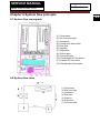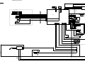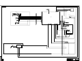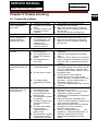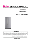
1
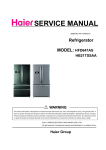
SERVICE MANUAL Order No. Ref1104S002V0 Refrigerator MODEL: HFD647AS HB21TSSAA WARNING This service info rmation is des igned for e xperienced repair technicians only and is not designed for use b y the general public. It dose not contain warnings and cautions to advice non-technical individuals of potential dangers in attempting to service a product. Product powered by electricity should by serviced or repaired only by experienced professional technicians. Any attempt to service or repair the product or products dealt with in this service information by anyone else could result in serious injury or death. ◎2011 (HAIER ELECTRICAL APPLIANCES COR. LTD) All right reserved. Unauthorized copying and distribution is a violation of law . Haier Group SERVCE MANUAL Model:HFD647AS/HB21TSSAA Contents Table of Contents ·········································································································· 1 1. General Information·································································································· 4 1-1. General guideline ······························································································· 4 1-2. Insurance test····································································································· 4 1-3. How to read this Service Manual········································································ 5 2. Product Feature ········································································································ 6 2-1. Specifications ····································································································· 6 2-2. Main Functions ··································································································· 7 2-3. External views ···································································································· 8 2-4.How to use the crisper ························································································9 2-5.How to use the Delicatessen drawer 9 3. Disassembly ············································································································ 10 3-1. Installing the Door Handle ················································································ 10 3-2. Installing and Removing Door ·········································································· 12 3-3. Removing and installing Lower Freezer Drawer (If required)··························· 13 3-4. Water line installation ······················································································· 14 3-5. Kick plate installation ························································································ 15 3-6. Height-adjustable shelf ····················································································· 15 3-7. Removing Crisper Cover ·················································································· 16 3-8.Replacing the light bulb (Refrigerator)······························································· 16 4. Control and display system ·······················································································17 4-1. Control display board························································································ 17 4-2. Artificial intelligence setting ·············································································· 17 4-3. Locking / Unlocking setting··············································································· 17 4-4. Quick freezing setting ······················································································· 17 4-5.Quick refrigerating setting ··················································································18 4-6. Switch off ice-maker ··························································································18 4-7. Quick ice-making function·················································································18 4-8.Te mperature setting and adjustment ·································································19 2 SERVICE MANUAL Model: HFD647AS/HB21TSSAA 4-9. Door-open warning ·······················································································19 4-10. Energy saving display ··················································································19 4-11.Power off memory ························································································19 4-12. Time adjustment and display ······································································· 19 4-13. Ambient temperature display ·······································································19 5. Control principle and related test functions·························································· 20 5-1. Air Damper······································································································ 20 5-2. Control principle of fan motor·········································································· 20 5-3. Defrost control principle ·················································································· 20 5-4. Ice- making process ························································································21 5-5. Self-testing Function 22 5-6. Ice-maker Inspection Mode 23 6. System flow principle ······························································································· 24 6-1. System flow scenograph················································································· 24 6-2. System flow chart···························································································· 24 7. Circuit diagram·········································································································· 25 7-1. Main control PCB diagram ·············································································· 25 7-2. Brief principle diagram ···················································································· 27 7-3.Sensor and error code ····················································································· 28 7-4. Display Error Codes Information ····································································· 28 8. Water line map ···········································································································29 8-1.Th e water line sketch map ···············································································29 8-2.Water line scenograph ·····················································································30 8-3. Water inlet quantity setting (HFD647A*) 30 9. Trouble shooting ·······································································································31 9-1.Frequently problems·························································································31 3 SERVICE MANUAL Model: HFD647AS/HB21TSSAA Chapter 1 General Information 1-1. General Guidelines When servicing, observe the original l ead dress. If a short circuit is found, replace all parts which have been overheated or damaged b y the short circuit. After servicing, see to it that a ll the pr otective devices such as insulation barriers, insulation p apers shields are pro perly installed. After servicing, make the following leakage current checks to prevent the customer from being exposed to shock hazards. 1) Leakage Current Cold Check 2) Leakage Current Hot Check 3) Prevention of Electro Static Discharge (ESD) to Electrostatic Sensitive 1-2. Insurance test 1. Check if there is any leak of current. 2. Cut out the power supply before the repair to avoid an electrical shock hazard. 3. In the case of a live-line test, insulating gloves should be worn to avoid potential electrical shock. 4. Confirm the rated current, voltage and capacity before testing with any kinds of instruments. 5. Watch if the upper door is open when you check something at a lower position. 6. Take out every part in the cabinet before moving the machine, especially things like panels (e.g. glass shelf). 7. Please wear int act cotton gloves when repair an y parts of the evaporator, so that scratches by the sharp finscan be avoided. 8. If there is a breakdown with the refrigeration system, please surrender the machine to the service center, else the leaked refrigerant may pollute the atmosphere. 9. The refrigerator use AC of 220V with a frequency of 50Hz. 10. A big fluctuation of voltage (exceed the range 187~242V) may cause a start failure of the refrigerator, a burn -out o f the control p anel and compressor, or an abn ormal sound from the compressor in operation. In this condition an automatic voltage regulator over 750W should be added. 11. Take care not to damage the supply line. Don’t yank at the line; pull the plug out gently from the receptacle. Don’t press the line under the cabinet or step on it. Take care not to roll on or damage the supply line when moves the machine from the wall. 12. In the case of leakage of inflammable gases like carbon monoxide, open the door and windows. Don’t pull out or insert the plugs of the appliance. 13. Don’t touch the refrigeration surface of the freezing compartment when the refrigerator is in operation, especially when your hand is wet, else you may be glued to the surface. 14. Pull out the plug of power suppl y du ring clearan ce or power out age. Wait at least five minutes to resume the power supply in order to prevent damage to the compressor caused by continuous restart. 4 SERVICE MANUAL Model:HFD647AS/HB21TSSAA Photo used in this manual The illustration and phot os used in this Manual may not base on the final design of products, which may differ from your products in some way. 1-3. How to read this Service Manual 1-3-1. Using Icons The meaning of each icon is described in the table below: Note: A “note” provides information that is not indispensable. Caution: A “caution” is used when there is danger, through incorrect manipulation, may damage equipment, loose data, get an unexpected result or has to restart (part of) a procedure. Warning: A “warning” is used when there is danger of personal injury. Reference: A “reference” guides to find additional information on a specific topic. 5 SERVICE MANUAL SSAA Model: HFD647AS/HB21T Chapter 2 Product Feature 6 2-1. SPECIFICATIONS 1 Model HFD647AS H B21T SSAA Photo Refrigerator-Freezer Refrigerator-Freezer Product description (Refrigerator/Freezer) Type of ap pliance (FS=free standing / BI= FS FS built-in) Type of cooling system (NF=no frost/ S=static) NF NF 4* 4* Climate class* Freezer compartment / Star rating 2 Key features Total gross volume 518 507 A A Frost free system yes yes Defrost water outlet yes Air circulating ventilator yes yes R134a/ 160g R 600a/ 75g C-P C-P 220V-240V~/ 50 220V-240V~/ 50 Total storage volume Defrosting (M=manual L A=autom atic) Energy consumption / year Kind of coolant Foaming components 3 Technical data Voltage / frequency V/Hz Temperature range (from>to) °C -22 ~ 7 -22 ~ 7 220 220 K K F= flat / R= rounded / S= streamline S S Inside color w Input power W Cooling system: K=Compressor / A=Absorption 4 yes Door: Hinged (r =right l =left) / reversible Freezing compartment integrated with door w R / L R / L Yes Yes 4 / - 3 / - Shelves: Number Fridge / Freezer Type (gr=grill / g=glass / p=plastic) Color w-white / g=green / t=transparent. g / P t g / P t SERVICE MANUAL Model: HFD647AS/HB21TSSAA Adjustable (Y=yes / N=not) Yes Yes Drawers: Plastic drawers (fully freezing comp.) n°. 2 1 Half freezing comp n°. 2 2 w/t w/t Chiller (t) Chiller (t) t t Interior Interior Interior Interior Yes Yes Adjustable thermostat Yes Yes Fast freeze switch /-function Yes Yes Deodorizing Yes Yes Color of drawer (w=white/t=transp./g=green) Crisper: Chiller / Meat (salad crisper) transparent / white Vegetable crisper(s) transparent / white 5 Equipment & accessories Con trol panel: Interior / exterior Thermometer interior / exterior Over temperature alarm LED / acoustic Interior light W Yes Yes Freeze pack(s) n° 2 2 A M ice maker Manual/ Automatic Ice cube tray(s) n° 1 1 Adjustable feet front / rear n° 2 /FRONT 2 /FRONT -/yes -/yes 245 245 B B Castors front / rear Length of cable/incl. plug cm Condenser Back / Integrated 6 7 8 Product dimensions Unit dimensions ( H / W / D) cm 177/91/75 177/91/75 Net weight kg 135 130 Packing dimensions (H / W / D) cm 186/98/76 186/98/76 Gross weight kg 148 143 English English Packing dimensions & load ability Service User manual 2-2. Main Functions ◆ Removable automatic icemaker ◆ Foldaway wine holder. ◆ Large crisper with humidity adjustment. ◆ Holiday function. ◆ Fridge storage compartment can be set on/off separately. ◆ Intelligent alarm function: automatic alarm at over temperature, malfunction, door open. 7 SERVICE MANUAL Model: HFD647AS/HB21TSSAA 2-3. External views 8 SERVICE MANUAL Model: HFD647AS/HB21TSSAA 2-4. How to Use the Crisper The appliance is equipped with a crisper for vegetable and fruit storage. You can set the humidity to meet your storage needs. 1. Turn the humidity regulator (located at the upper right Humidity regulator corner of the crisper) up to get a higher humidity suitable for storage of cucumber, grape, kiwifruit and persimmon etc. 2. Turn the humidity regulator (located at the upper right corner of the crisper) down to get a lower humidity suitable for storage of strawberry, orange, bean, garlic, watermelon, plum and tomato etc. 2-5. How to Use the Delicatessen Drawer The appliance is equipped with a delicatessen drawer with a temperature range from-2°C~+3°C.The temperature can be adjusted by the air control knob to meet your storage needs. 1. Turn the air control knob left (weak) to reduce the cooled air moving in the delicatessen drawer and maintain a higher temperature; 2. Turn the air control knob right (strong) to increase the cooled air moving in the delicatessen drawer and maintain a lower temperature. 9 SERVICE MANUAL Model: HFD647AS/HB21TSSAA Chapter3 Disassembly 3-1. Door handle installation 3-1-1.Refrigeration door handle 1. Retrieve the handle clearly marked for the Refrigerator Door that needs attachment. 2. Insert the Handle Connecting Screws into the holes provided on the Refrigeration Door. Using a hand held screwdriver tighten the Handle Connecting Screw until the screw threads disappear and the first flat surface of the Handle Connecti ng Screw tou ches the Refrigerat or Do or surface ( as shown in illustration1- step2). Do not over tighten-damage to the door can occur. 3. Place the Refrigeration Door Handle onto the Handle Connecting Screws using the upper hole of the “Top” Refrig eration Doo r Handle (as shown in il lustration 1-step3); The Refrigeration Door Handle should rest comfortably to the door on these Connecting Screws. 4. Insert the Connecting Bolt into the hole at the top of the Refrigerator Door Handle. Using the provided Hex Driver and tighten until the handle is fixed firmly to the door. Repeat this process for the “Bottom” of the Refrigeration Door Handle (as shown in illustration 2-step4) .Be careful when tightening not to scratch the door surface. 5. Place Bolt Covers into the holes on the handle at the top and bottom and push into place (as shown in illustration2- step5). 6. To disassemble the Refrigeration Door Handle, follow these directions in reverse. 10 SERVICE MANUAL Model: HFD647AS/HB21TSSAA 3-1-2.Freezer door handle 1. Retrieve the handle clearly marked for the Freezer Door that needs attachment. 2. Insert the Handle Con necting Screws into the holes provide d on the Freezer Doo r. Using a hand held screwdriver tighten the Handl e Connecting Screw until the screw thread s disappear and the first flat surface of the Handle Connecting Screw touches the Freezer Drawer surface (as shown in illustration1- step2). Do not over tighten-damage to the door can occur. 3. Place the Freezer Drawer Ha ndle onto the Handle Connecting Screws (as shown in illustration1 –step3).The Freezer Drawer Handle should rest comfortably on these Connecting Screws. 4. Insert the Connecting Bolt in to the holes on the bottom of the Freezer Drawer Handle marked “Left”. Using the provided Hex Driver and tighten until the handle is fixed firmly to the door. Repeat this process for the “Right” side of the Freezer Drawer Handle (as shown in illustration 2-step4).Be careful when tightening not to scratch the door surface. 5. To disassemble the Refrigeration Door Handle, follow these directions in reverse. 11 SERVICE MANUAL Model: HFD647AS/HB21TSSAA 3-2 Inst alling and Removing Door Precautions During Dismantling and Installation of The Door You may not need to remove the doors! But if you have trouble getting the unit into it s final lacation,please follow the below door removal and in stallation instructions. It is suggected, for your safety, to have two or more people to assist you in completin g the below task to avoid bodily injury, product damage,or properly loss. 3-2-1. Right French Door Removal and Installation 1. Remove the screws on the top hinge cover 2. Using a screwdriver ,remove the top hinge screws. Remove the hinge, then t ake the refrigerator door off and place it aside for the time being. 3. Remove the middle hinge,if needed. 4. Install the refrigerant door in reverse sequence, When lifting up the refrigerator hinge and separating it from the door body,please be careful not to drop the door slanted forward. 12 SERVICE MANUAL Model: HFD647AS/HB21TSSAA 3-2-2. Left French door removal and installation 13 1. First remove the top hinge cover as above. 2. Disconnect the water line from back of unit 3. Remove the hinge screws using a screwdriver, and take off the hinge, then remove the door body and place it in a safe position. Disconnect the wir e cable conn ector, ground wire a nd pull water line out from cabinet. 4. Please remove the middle hinge, if needed. 5. Install the door in the reverse order. When lifting the hinge as it sep arates from the door, be car eful it does not lean for ward and fall, causing you bodily harm or damaging the door. 3-3.Removing and installing Lower Freezer Drawer (If required) 1. First open the drawer as far as possible, and then remove the screw on each side of the drawer. 2. Then pull the drawer body up and towards you, and put it aside in a safe place. 3. Install the drawer in the reverse order. Keep children and pets from playing inside the lower drawer as a hiding place. Use caution after drawers and removed, due to the possibility of the plastic track protruding from unit HFD647: HB21TSSAA SERVICE MANUAL Model: HFD647AS/HB21TSSAA 3-4 Water line installation Installation of connecting valves and plumbing must follow all local plumbing guidelines, laws and restrictions. Install the shutoff valve on a cold water supply line that is frequently used 1. Turn off the main water supplying pipe routine Turn on the nearest tap till the water pipe is cleaned completely 2. Choose the position of the valve Choose a position for the valve that is easy to be approached. It is recommended that the valve is connected to the side of a vertical water pipe, and if it is really needed to connect the valve to a level water pipe .Connect it to the upside of the water pipe not the downside, in case the sediment may flow out from the water pipe. 3. The hole of the drill valve Drill a hole of 1/4inches on the water pipe using a sharp drill (even using an automatic valve). Clean the burr left on the water pipe by the drill. Use care not to allow water to flow into the drill 4. Tighten the shutoff valve 5. Tighten the pipe tip Tighten the bolts of the pipe tip till the closing begins to expand. Don’t let the bolts lf the pipe tip be too tight, otherwise the water pipe is pressed flat. 6. The deposing line of the pipe The deposing line between the cold water pipe and the refrigerator Drill a hole on the wall or on the floor that is near the wall to a great degree, and let the pipe line go through the hole Assure the pipe has an enough margin area (about 8 inches [2.4 meters] and make it be three circles with the diameter of each circle about 10 inches [25centimeters].and after this installment is done, the refrigerator can be moved away from the wall. 7. Connect the pipe to the valve Put the Tightened nuts and the copper shaft on the end side of the pipe and connect the pipe to the stopping valve. Make sure that the pipe is cut into valve completely. Tighten and press the nut. 14 SERVICE MANUAL Model: HFD647AS/HB21TSSAA 8. Clean the Pipe 15 Power the main water supply till the water in the pipe becomes clean. Turn off the water valve after having used water of about 1V. 9. Connect the pipe to the refrigerator. Before connecting the pipe to the refrigerator, make sure that the power line is not cut into the electric plug on the wall. (1) Tighten the water pipe on the water valve and take the nut off the water pipe. (2) And then ,as shown in the figure ,connect the end side of the water pipe to the water valve; tighter the water pipe using tightening nuts. 3-5. Kick Plate Installation The kick plate is packed in the fresh food compartment. Attach the panel with the screws provided. 3-6. Height-adjustable Shelf The height of shelf can be adjusted to meet your storage needs. To adjust the shelf height, remove the shelf first. The steps are as follows: 1.tilt the shelf up at front, and lift it up and out of tracks. 2. T o replace the shelf, wi th shelf front raised slightly, engage the lugs in tracks. Then lower shelf front until it locks into position. To replace To remove SERVICE MANUAL Model:HFD647AS/HB21TSSAA 3-7. Removing Crisper Cover Take out the crisper and put it away. Lift up the cover end (1) and remove it (2). 3-8. Replacing the Light Bulb (refrigerator) Bulb specifications: 220V~, 25W Socket: E14 (DO NOT use a bulb over 25W) 1. Unplug the appliance 2. To remove the light shield, press the stopper At rear out of the square hole Pull the shield backward until the retainer is Separated from the square hole 3. Turn the bulb anticlockwise and out. Replace a Bulb of the same specifications in the reverse sequence of removal. 4. To replace the light shield: Engaged the retainer Into the square hole and then press the shield Rear forward until the stopper is locked in the square hole. 16 SERVICE MANUAL Model:HFD647AS/HB21TSSAA Chapter 4 Control and display system (1) Control display board A—Freezer temperature adjustment key B—Functio n setting key C—Refrigerator temperature adjustment key D—Function confirmation key E—Freezer temperature indicator F—T imer indicator G—Ambient temperature indicator H—Refrige rator temperature indicator I— Artifical intelligent indicator J—Quick freezer indicator K—Quick refrigerating indicator M—Quick ice-making indicator L—Icema ker indicator N—Lock indicator 17 SERVICE MANUAL Model: HFD647AS/HB21TSSAA 18 SERVICE MANUAL Model: HFD647AS/HB21TSSAA 19 SERVICE MANUAL Model: HFD647AS/HB21TSSAA Chapter 5 Control principal and related test functions 5-1. Air Damper 20 (1) The refrig eration air damper is controlled with the fresh food storage te mperature sensor R SNR. (2) The air damper is closed from the beginning of defrosting until 15 minutes after the defrosting is finished. (3) Upon initial powering on or resetting of the control panel, the air damper conducts a close-and-open cycle before acting according to the control conditions in item (1). (4) The air damper will be forced to conduct an open-and-close cycle if it has been closed for 1 hour. After that, its closing/opening will be controlled by RSNR. (5) The air damper will automaticlly close when REF. door has been opend over 2 minutes. 5-2. Control Principle of the Fan motor Control principal of the evaporator fan motor and fresh food damper. 1 . When a fresh food door is opened, the evaporator fan motor will operat e on high speed and the damper will be full open. After 2 minutes with the door open, the damper will close but the evaporator fan motor will operate according to the compressor function. 2. The evaporator fan motor will not operate if the freezer door is open ,even if the fresh door is open. 3. An error code alerting of a fan motor problem will appear (see error code section) if the motor speed is below 300rpm or does not operate for longer than 30 seconds during the run cycle. Condenser fan motor’s controlling: The motor works with compressor synchronous.condenser fan motor has a 12V’s power supply voltage while the rotate speed 1150RPM on normal. And high speed operation is 13.5v - 1300rpm. 5-3.Defrosting Control Principle of HB21TSSAA & HFD647* Refrigerator Compressor turns off Defrost heater turns on Defrost heater turns off Compressor turns on Freezer Fan turns on Air Damper opens FC fan turns off Air Damper Closes Accumulative compressor run time 7 hours Defrost is terminate when the sensor reaches +7℃ Defrost aborted after 120 minutes Failing to reach +7℃ ED displayed on LCD paned as fault 7 minutes Defrost Time is about 30 minutes 5 minutes 3 minutes Back to Normal Run SERVICE MANUAL Model: HFD647AS/HB21TSSAA Defrost Heater control rule Defrost heater will be controlled according to the following : 1 The very first defrost will occur 4 hours after cabinet has been switched on or after a replacement control board fitted. 2 If the PC sensor temperature is greater than 10℃ a defrost will occur. 3 If the FC temperature is above –5℃ a defrost will occur. 4 If the PC & FC doors have been opened more than 5 times before the cabinet has run for 5 hours after first being switched on. 5 If none of the above conditions (1) (2) (3) (4) have occurred a defrost will take place after 7 hours of accumulative run time, terminating when the defrost sensor reaches +7℃ 6 The defrost will be aborted after 120 minutes with the defrost sensor failing to reach +7℃ 7 Fault code ED will be displayed. 8 If the defrost sensor fails, a forced defrost will occur every 120 minutes. 9 If Fast freeze or fast fridge is selected while the cabinet is in defrost mode, these modes will not occur until the defrosting has been completed. In order to minimize the rise in temperature while defrosting the system will go into advance cooling lower the FC temperature below the normal switch point by –3℃ . If the cabinet cannot reach this temperature with in 30 minutes a forced defrost will occur. 5-4 Ice-making process (HFD647AS / HFD647AW) 1. Water in: The machine let water into ice-maker after ice releasing action 2. Ice-making delay time: Include two conditions, one condition is that the ice-ma king time reach to 60 minutes, another conditio n is that the ice-maker senor te mperature is low er than -14℃. It must be meet these two conditions, the ice maker could overturn and make ice cube. 3. Ice-detection: When ice- maker is under w orking status, ice-measure st aff move d ownward firstly to detect if the ice is full. If the measure-staff can mo ve to the lowest position, it means that the ice in ice-drawer is not full, and it can continue next ice-releasing action. If the me asure-staff can not move to the lowest position, machine will take for the ice in ice-drawer is full, and return to ice-making delay time to wait another ice-detection action, and then come into being cycle. 4. Ice-releasing: If the result of ice-detection is not full, ice- box w ill rot ate to release ice. After ice-releasing, machine going on another water in action, and then come into being cycle. 21 SERVICE MANUAL Model: HFD647AS/HB21TSSAA 5-5 Self-testing Function of HB21TSSAA & HFD647A* Refrigerastor (1) Hold the REF TEMP setting button (C) ,FRZ TEMP setting button (A) and OK button (D) three keys for 3 seconds, until it show T1 T1 with a buzzer, the products will enter compulsive starting mode. (2) The same operation like step (1) under mode TEST1 until it show T2 T2, then the product will enter compulsive defrosting mode (3) The same operation like step (1) under mode TEST2 until it show T3 T3, then will enter inspection mode of mullion heater and beam heater . the product (4) Under TEST3 mode, keep pressing the REF TEMP setting button (C) ,FRZ TEMP setting button (A) and OK button (D) three keys for 3 seconds, the refrigerator will quit TEST mode and back to normal. MODE OPERATION TEST1 Keep pressing REF TEMP, FRZ TEMP and OK button three (For keys for 3 seconds testing the until it show T1 T1, capability the products will enter compulsive of cooling) starting mode. CONTENT NOTE 1) compressor start working Mode TEST1 continues until exit 2) freezer fan motor start manual working 3) cooling fan motor start working 4) defrost heater closed 5) air damper open 90° 6) show T1/T1 at refrigerator/freezer setting of display board 22 SERVICE MANUAL Model: HFD647AS/HB21TSSAA TEST2 Under mode TEST1, Keep pressing REF (For TEMP, FRZ TEMP testing the and OK button three defrost keys for 3 seconds system) until it show T2 T2, then the product will enter compulsive defrosting mode TEST3 Under mode TEST2, Keep pressing REF TEMP, FRZ TEMP (For and OK button three testing keys for 3 seconds assist until it show T3 T3, heaters) then the product will enter inspection mode of mullion heater and beam heater . BACK TO Under TEST3 mode, NORMAL keep pressing REF TEMP, FRZ TEMP and OK button three keys for 3 seconds, the refrigerator will quit TEST mode and back to normal 1) compressor shutdown When temperature around defrost 2) freezer/cooling fan motor sensor above 7 degree, appliance shutdown will exit <Force defrost MODEL> 3) defrost heater start working after heater working 1 minute! 4) mullion heater shutdown When temperature around defrost 5) air damper and its heater sensor below 7 degree, heater will shutdown work continually until reach 7 6) freezer/refrigerator setting degree, appliance then exit display T2/T2 at display board 1) compressor shutdown Heaters of air damper and 2) freezer/cooling fan motor refrigerator mullion heater is under shutdown working. exit the inspection 3) defrost heater shutdown program after 30 minutes and back 4) Mullion heater and beam to normal heater start working 5) air damper heater start working 6) freezer/refrigerator setting display T3/T3 at display board Function back to normal (compressor start to work 7 minutes later) 5-6 Ice-maker Inspection Mode Under Unlock state, press both Function setting button (B) and OK button (D) for 3 seconds until hear one sound of buzzer, products enter ice-maker inspection mode. In this mode, Ice-maker will forced turnover once, then inhale water according pre-setting water volume. 23 SERVICE MANUAL Model: HFD647AS/HB21TSSAA Chapter 6 System flow principle 24 6-1.System flow scenograph (1) Compressor (2) Hot connector pipe (3) Condensor (4) Freezer anti sweat tube (5) Drier filter (6) Capillary (7) Evaporator (8) Suction pipe (9) Connector pipe (10) Compressor DC fan motor (11) Freezer DC fan motor (12) Defrost steel tube heater 6-2.System flow chart (1) Compressor (2) Dew proof pipe (3) Condenser (4) Drier filter (5) Capillary (6) Evaporator (7) Connector pipe HFD647AS HFD647AW: 25 power cord assembly power board 0064001235 BL BN N L +16V 1 fridge electronic damper L N 3 5 environment sensor 7 CH5 6 +16V GND +5V WH BK BK CH8 1 GN fridge vertical girder heater 9 7 5 4 9 3 CH10 2 BN 3 BK 1 CH4 5 fridge lamp(up) 7 BL 1 CH9 2 3 4 5 6 2 BN YW 5 6 11 1 CH7 4 3 9 fridge lamp (down) GY GY GY 1 BN fridge sensor fridge chamber freezer door RD WH BL BK 7 BL BL WH WH t° CH6 CH1 RD WH BL BK 5 door switch,fridge 3 OG OG main control board 0064001128C 3 1 1 RD YW BL WH BK BK OG OG WH WH 2 damper heater WH 1 damper motor RD YW BL BK BK t° BK RD GN BK BK +5V display panel 0061800041 BN BL RD GN GND GN BK RD BL GY BK BK RD RD OG OG GY BL BN PR GN YW GY ice-maker 0064001224 t° BK t° BK freezing sensor RD/WH BL/WH OG OG freezer door switch GY BL BN condensor fan PR GN YW evaporator fan BL/WH RD RD fuse t° defrost sensor defrost sensor cable defrost heater fuse RD/WH freezer upright beam heater fuse GY water inlet heater YW BN freezer room lamp compressor inverter PCB INPUT:220~240V OUTPUT:220-240V FREQUENCY CONVERSION BOARD RD BL N BL RD ice-maker water inlet valve resistance capacitance module freezer chamber 0POWER PLUG (DOOR DISPLAY PANEL) t° 1 3 5 ENVIRONMENT 7 REFRIGHRATOR DAMPER CH5 6 L DAMPER MOTOR N UPRIGHT BEAM HEATER DAMPER HEATER CONTROL PANEL 0061800135 CH1 REFRIGERATOR DOOR 3 5 7 9 1 t° 3 REFRIGHRATOR SENSOR 2 4 1 REFRIGHRATOR DOOR SWITCH 1 CH11 3 1 CH4 5 REFRIGHRATOR LAMP t° 7 1 2 3 CH10 4 5 6 1 2 CH8 3 4 FREEZER SENSOR 9 REFRIGHRATOR LAMP 5 6 11 REFRIGHRATOR ROOM FREEZER DOOR SWITCH COOLING FAN FREEZER FAN FUSE1 t° DEFROST SENSOR FREEZER CONTROL CABLE DEFROST HEATER FUSE2 FREEZRE LAMP COMPRESSOR INPUT:220-240V OUTPUT:220-240V INVERTER PANEL N FREEZER ROOM 借(通)用件登记 描 图 CAD 专用号: 入库签字 旧底图总号 HB21T接线图 底图总号 签 字 日 期 版 次 标记 标记 处数 分区 设计 制图 会签 审核 更改文件号 签名 年 月 日 工艺 阶段标记 标准化 S 审定 共 1 张 批准 质量 比例 1:1 第 1 张 青岛制冷技术研究所 项目经理 HB21TSSAA SSAA SERVICE MANUAL Model:HFD647AS/HB21TSSAA 7-3. Sensor And Error Code 28 Senor Position: Remark: There is no ICE sensor for model HB21TSSAA. ERROR CODE LISTS: Error description Error Code Meanings of Code (R SNR) Refrigerator sensor malfunction F1 R1 SNR short circuit or open circuit (F SNR) Freezer sensor malfunction F2 F SNR short circuit or open circuit (RT SNR) Ambient temperature sensor malfunction F3 RT SNR short circuit or open circuit (D SNR) Defrost sensor malfunction F5 D SNR short circuit or open circuit (ICE SNR) Icemaker sensor malfunction F6 ICE SNR short circuit or open circuit Freezer fan motor malfunction E1 No single send out more than 30 seconds Cooling fan motor malfunction E2 Defrost Heating System error Ed Icemaker system malfunction Er No single send out more than 30 seconds Defrost sensor temperature can’t reach to 7 centigrade after temperature rise more than 2 hours Can’t detect on/off single when icemaker rotate 7-4 Display Error Codes Information The machine will not display error codes automatically when it is in malfunction. SERVICE MANUAL Model: HFD647AS/HB21TSSAA Under Locked st ate, hold and press both FRZ TEMP setting button (A) and OK button (D) for 3 seconds, with a buzzer , the products will enter error codes display mode. The same as above operation can recover to normal disp lay st atus. If no manually operation, it will recover to normal display status after 1 minute. Chapter 8 Water Line Map (HFD647A*) 8-1. The water line sketch map A B B C C D Connection the water pipes for the ice maker: 1. Connect tap water to the inlet A of the main valve 2. Connect the outlet B of the main valve to the water filter then connect the pipe to the water bottle. 3. The water that is chilled in the wate r bottle flows to the inlet C of the distributor , and then enters into pipe D through the icemaker valve to supply water to the icemaker; 29 SERVICE MANUAL Model: HFD647AS/HB21TSSAA 8-2. Water line scenograph 8-3. Water inlet quantity setting Water inlet quantity can be controlled through button on the display control panel. Under Locked state, press A, B, C, D four keys simultaneously for 3 seconds with the buzzer beeps once, then enter into inl et quantity a djustment. The inlet time can be set between 5 seconds to 1 1 seconds, press FRZ TEMP button and REF TENP button to adjust water inlet time. 30 SERVICE MANUAL Model: HFD647AS/HB21TSSAA Chapter 9 Trouble shooting 9-1. Frequently problem Water/moisture/frost in the refrigerator Moisture accumulates Hot and moist climate. Accumulation of frost and moisture on the refrigerators The door is not closed accelerate in such climate. inner walls tightly Make sure the refrigerator is level and The door is opened too there is no food or container interfer ing frequently or for too with the door long time Do not open the door so frequently Water/moisture/frost on outside surface of the refrigerator Moisture accumulates Damp climate It is normal in damp climate. The moisture on the refrigerator’s The refrigerator door is will decrease when the humidity drops. outside surface or not closed tightly. This Make sure the refrigerator is level and between two doors causes mixing of the there is no food or container interfer ing cold air in the with the door refrigerator with the warm air outside it Refrigerator operation The compressor does The refrigerator is in It is normal for an auto matic defrosting not work defrosting cycle. refrigerator. The refrigerator is not Verify the plug is plugged in the socket plugged into a power firmly. outlet. Press the “Power” button for 3 second or The refrigerator is in more to restart the refrigerator or turn the OFF state. knob from OFF to temperature selection position. The fridge storage The air door cable is not Check if the air door cable is not compartment does not connected properly. connected properly and i nstall it correctly work if not so. Verify that th e air door acts normally with the Fridge ON/OFF key on The fan does not work the display panel The fan does not work while the refrigeration air door is open. Please check if the door on-off behind the front The fridge storage decoration strip is installed prope rly. compartment is turned Reinstall it correctly if not so. off Turn on the fridge storage comp artment manually The refrigerator runs The indoor or outdoor In this case, it is normal for the frequently or runs for temperature is high refrigerator to run longer. too long period The refrigerator has Normally, it takes 8 to 12 hours for the been powered off for a refrigerator to totally cool down. period of time. Icemaking process makes the refrigerator The automatic icemaker to run longer. is operating. Warm air enters the refrigerator and The door is opened too causes it to start frequently. Please do not frequently or for long open the door so frequently. periods. Make sure the refrige rator is level place The door of the fridge / and there is no food or container freezer storage interfering with the door. compartment is not Set the temperature higher until tightly closed. satisfactory refrigerator temperature is The temperature setting obtained. It takes 24 hours for the for the freezer storage refrigerator temperature to become compartment is too low stable. 31 SERVICE MANUAL Model: HFD647AS/HB21TSSAA Too high temperature Too high temperature in the fridge/freezer storage compartment The door gasket of the fridge/freezer storage compartment is dirty, worn, cracked or mismatched. The condenser is dirty. Clean the condenser. The door is opened too frequently or for too long periods of time Temperature is set too high The door is not closed tightly The condenser is dirty The temperature is set too high Warm air will enter the refrigerator whenever the door is opened. Try to open the door as infrequently as possible. Reset the temperature. Make sure the refrigerator is on a level surface and there is no food or container interfering with the door. Clean the condenser. Set the freezer temperature lower. It takes 24 hours for the temperature of the refrigerator to become stable. The temperature in the freezer storage compartment is too high while the temperature in the fridge storage compartment is OK The temperature in the The temperature is set fridge storage too high compartment is too high while the temperature in the freezer storage compartment is OK Bad odors in the refrigerator The inside of the The inside of the refrigerator is dirty refrigerator needs cleaning Food with strong odor is stored in the refrigerator If you hear... Beeps The fridge storage compartment door is open The temperature in the freezer storage compartment is too high Abnormal sound The refrigerator is not located on a level surface The refrigerator touches some object around it Slight sound similar to It is the sound of the that of flowing water refrigerating system Heating of cabinet The de-dew tube is de-dewing Clean or replace the door gasket. Leakage g ap of door gasket can cause longer running time of the refrigerator in order to maintain desired temperature. Set the fridge temperature lower. It takes 24 hours for the temperature of the refrigerator to become stable. Clean the internal of the refrigerator Wrap the food tightly. Close the manually The alarm is normal when it is first started due to relatively higher temperature. Adjust the feet to level the refrigerator. Remove objects around it. door or silence the alarm Normal. It is a process to prevent dewing. It is a normal phenomenon. 32 Sincere forever Haier Group Haier Industrial Park, No.1, Haier Road 266101, Qingdao, China http://www.haier.com