1
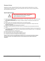
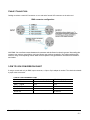
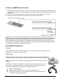
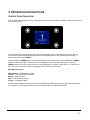
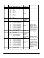
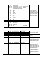
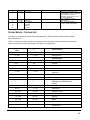
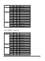
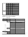
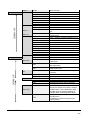
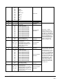
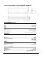
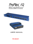
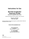
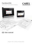
RGBW 3x4 Brick & 10x4 Batten
USER MANUAL
TABLE OF CONTENTS
1. INTRODUCTION ............................................................................................................................................ 3
PRODUCT OVERVIEW ............................................................................................................................................ 3
W HAT IS INCLUDED .............................................................................................................................................................3
AVAILABLE OPTIONS............................................................................................................................................................3
UNPACKING INSTRUCTIONS.................................................................................................................................................3
POWER REQUIREMENTS .....................................................................................................................................................3
FREQUENCY SETTING .........................................................................................................................................................4
SAFETY INSTRUCTIONS .......................................................................................................................................................4
2. SETUP ............................................................................................................................................................ 5
FUSE REPLACEMENT ............................................................................................................................................. 5
FIXTURE LINKING .................................................................................................................................................. 5
DMX DATA CABLE ................................................................................................................................................ 5
CABLE / CONNECTORS .......................................................................................................................................... 6
3- TO 5-PIN CONVERSION CHART ........................................................................................................................... 6
SETTING UP A DMX SERIAL DATA LINK .................................................................................................................. 7
FIXTURE MOUNTING / RIGGING .............................................................................................................................. 7
3. OPERATING INSTRUCTIONS ....................................................................................................................... 8
CONTROL PANEL NAVIGATION ............................................................................................................................... 8
MENU MAP RGBW 10X4 ...................................................................................................................................... 9
DMX MODES SUMMARY 10X4 ............................................................................................................................. 11
RGB XPIX DMX CHANNELS 10X4 ....................................................................................................................... 12
RGB XPIX 16-BIT DMX CHANNELS 10X4 ............................................................................................................ 12
RGBW XPIX DMX CHANNELS 10X4 .................................................................................................................... 13
RGBW XPIX 16-BIT DMX CHANNELS 10X4 ......................................................................................................... 14
AUTOLINK MODE 1 10X4 ..................................................................................................................................... 16
AUTOLINK MODE 2 10X4 ..................................................................................................................................... 17
STROBE MODES 10X4 AND 3X4 ........................................................................................................................... 18
STROBE + RGB XPIX 10X4 AND 3X4 .................................................................................................................... 19
STROBE + RGBW XPIX 10X4 AND 3X4 ................................................................................................................ 20
MENU MAP RGBW 3X4 ...................................................................................................................................... 21
DMX MODES SUMMARY 3X4 ............................................................................................................................... 23
RGB XPIX DMX CHANNELS 3X4.......................................................................................................................... 24
RGB XPIX 16-BIT DMX CHANNELS 3X4 .............................................................................................................. 24
RGBW XPIX DMX CHANNELS 3X4 ..................................................................................................................... 24
RGBW XPIX 16-BIT DMX CHANNELS 3X4 ........................................................................................................... 25
AUTOLINK MODE 1 3X4 ....................................................................................................................................... 25
AUTOLINK MODE 2 3X4 ....................................................................................................................................... 27
STROBE + RGB XPIX 3X4 ................................................................................................................................... 28
STROBE + RGBW XPIX 3X4 ................................................................................................................................ 28
4. APPENDIX .................................................................................................................................................... 29
BASICS OF DMX CONTROL .............................................................................................................................................. 29
GENERAL MAINTENANCE.................................................................................................................................................. 29
LIMITED W ARRANTY ......................................................................................................................................................... 29
RETURN PROCEDURE.......................................................................................................................................... 30
CONTACT INFORMATION ................................................................................................................................................... 30
TECHNICAL SPECIFICATIONS 10X4 BATTEN .................................................................................................................... 31
TECHNCIAL SPECIFICATIONS 3X4 BRICK ......................................................................................................................... 32
Solaris LED RGBW 10x4 and 3x4 user manual version 3.8.1 031115
-2-
1. INTRODUCTION
PRODUCT OVERVIEW
®
These fixtures are linear LED fixtures with high-intensity RGBW single-chip Cree LEDs grouped into multiple
independent pixels. In-lens color mixing prevents multicolor shadows. Advanced fixture electronics deliver
flicker-free output with smooth 16-bit dimming.
In-lens color mixing.
Multiple control modes including parametric modes with effects, whole fixture control, and pixel control.
Flicker-free output with smooth 16-bit dimming.
16-bit DMX512 control.
WHAT IS INCLUDED
1x Solaris LED RGBW 10x4 or 3x4 fixture w/ heavy duty trunnions
1x Power cable
1x User manual
AVAILABLE OPTIONS
Partial frost strips
Heavy-duty bar yoke (Batten and Half-Batten only)
Lenses: 16°, 22°, 36°, 47°
UNPACKING INSTRUCTIONS
Upon receipt of the fixture, carefully unpack the carton and check the contents to ensure that all parts are
present and in good condition. Notify the shipper immediately and retain packing material for inspection if
any parts appear to be damaged from shipping or if the carton itself shows signs of mishandling. Save the
carton and all packing materials. In the event that a fixture must be returned to the factory, it is important
that the fixture be returned in the original factory box and packing.
POWER REQUIREMENTS
Before powering the unit, make sure the line voltage is within the range of accepted voltages. This fixture
accommodates 100-240VAC, 50/60Hz. All fixtures must be powered directly from a switched circuit and
cannot be operated with a rheostat (variable resistor) or dimmer circuit, even if the rheostat or dimmer
channel is used solely as a 0-100% switch.
When powered up, Solaris LED performs a preprogrammed internal test. On initial power-up the factory
default DMX address appears on the display screen and Solaris LED is ready for operation. After initial
power-up, the last-saved DMX address will appear.
Solaris LED RGBW 10x4 and 3x4 user manual version 3.8.1 031115
-3-
FREQUENCY SETTING
Depending on location, change the Default Frequency setting to match the mains power (e.g., US and
Canada should be set at 60Hz). Proper frequency setting will ensure minimum amount of visible artifacts
when using Solaris LED on camera.
SAFETY INSTRUCTIONS
Please read these instructions carefully. This user guide
contains important information about the installation,
usage and maintenance of this fixture.
Please keep this Operation Manual for future reference. If unit is sold to another user, make sure they also
receive this instruction booklet.
Ensure fixture is connected to proper voltage, and that line voltage is not higher than that stated on the
fixture.
Make sure there are no flammable materials close to the unit while operating.
Always disconnect from the power source before servicing or fuse replacement. Always use the fuse
specified in this manual.
Always use a safety cable when hanging fixture overhead.
Maximum ambient temperature (Ta) is 40°C (104°F). Do not operate fixture at temperatures above this
rating.
In the event of a serious operating problem, stop using the unit immediately. Repairs must be carried out by
trained, authorized personnel. Contact the nearest authorized technical assistance center. Only OEM spare
parts should be used.
Do not connect the device to a dimmer pack.
Make sure power cord is never crimped or damaged.
Never disconnect power cord by pulling or tugging on the cord.
Avoid direct eye exposure to the light source during operation.
Caution! There are no user serviceable parts inside the unit. Do not open the housing or attempt
any repairs yourself. In the unlikely event your unit may require service, please contact your
distributor.
Solaris LED RGBW 10x4 and 3x4 user manual version 3.8.1 031115
-4-
2. SETUP
Disconnect the power cord before replacing the
fuse. Always replace with the correct fuse type.
FUSE REPLACEMENT
Solaris LEDs use a 6A (10x4) and 4A (3x4) 250V slow-blow fuse. To replace fuse:
1. With a screwdriver turn the fuse cap counter-clockwise to remove fuse cap with fuse.
2. Replace fuse attached to fuse cap.
3. Reinsert fuse cap with new fuse and tighten clockwise.
FIXTURE LINKING
A DMX data link is needed to operate one or more fixtures via a DMX-512 lighting console. The combined
number of channels required by all the fixtures on a DMX data link determines the number of fixtures the DMX
data link can support.
Important: Fixtures on a DMX data link must be daisy-chained in one single line. To comply with the
EIA-485 standard, no more than 32 devices should be connected on one data link. Connecting more
than 32 fixtures on one serial data link without the use of a DMX optically-isolated splitter may result in
deterioration of the digital DMX signal.
Maximum recommended DMX data link distance between fixtures: 984 ft. (300 meters).
DMX DATA CABLE
®
Use a ProPlex DMX cable or equivalent which meets the specifications for EIA RS-485 applications. Standard
microphone cables cannot transmit DMX data reliably over long distances. The data cable must have the
following characteristics:
2-conductor twisted pair plus a shield
Max. capacitance between conductors – 30 pF/ft.
Max. capacitance between conductor and shield – 55 pF/ft.
Max. resistance of 20 ohms / 1000 ft.
Nominal impedance 100-140 ohms
Solaris LED RGBW 10x4 and 3x4 user manual version 3.8.1 031115
-5-
CABLE / CONNECTORS
Cabling must have a male XLR connector on one end and a female XLR connector on the other end.
DMX connector configuration
CAUTION: Do not allow contact between the common and the fixture’s chassis ground. Grounding the
common can cause a ground loop, and your fixture may perform erratically. Test cables with an ohm
meter to verify correct polarity and to make sure the pins are not grounded or shorted to the shield or
each other.
3-PIN TO 5-PIN CONVERSION CHART
If using a console with a 3-pin DMX output connector, a 3-pin to 5-pin adapter is needed. The chart below details
a proper cable conversion:
3-PIN TO 5-PIN CONVERSION CHART
Conductor
3 Pin Female (output)
5 Pin Male (Input)
Ground / Shield
Pin 1
Pin 1
Data ( - ) signal
Pin 2
Pin 2
Data ( + ) signal
Pin 3
Pin 3
Do not use
Do not use
Do not use
Do not use
Solaris LED RGBW 10x4 and 3x4 user manual version 3.8.1 031115
-6-
SETTING UP A DMX SERIAL DATA LINK
1) Connect the male 5-pin XLR connector of the data cable to the female 5-pin XLR output of the DMX console.
Connect the other end of the data cable (female 5-pin XLR) to the male 5-pin XLR connector located on the
Solaris LED.
2) Connect from the fixture output as stated above to the input of the following fixture, and so forth.
3) Continue linking until the last fixture is connected in your DMX signal data chain.
IMPORTANT: In the AutoLink control modes, if the first fixture in chain is set to work in AutoLink 1 or 2
mode, it will take a priority over all subsequent fixtures in the chain. Note! In this case communication
between fixtures is done using a proprietary protocol, other DMX devices in the chain after the first
Solaris LED fixture will not run properly. Powering off one of the fixtures in data chain, will result in a
loss of signal for the remainder of the chain. When using an AutoLink mode, do not connect any other
type of fixtures in your Solaris LED fixture data link.
FIXTURE MOUNTING/RIGGING
Orientation
Solaris LED fixtures may be mounted in any position. Always make sure there is adequate room for
ventilation. Do not obstruct unit’s fan or vents.
Support Stand
Always use a professional stand rated to support weight greater than the Solaris LED weight (see
specifcations). Attach a TVMP spigot to the yoke of the Solaris LED and mount on the stand.
Rigging – Always consult a qualified, certified rigging engineer before suspending any fixture
overhead.
®
Use ProBurger couplers or equivalent C- or O-type clamps for attaching to truss. Do not
obstruct vents. Adjust the fixture angle by loosening both knobs and tilting the fixture as
needed. After establishing the desired position, retighten both knobs.
Always use safety cables!
When selecting installation location, consider routine maintenance.
Never mount fixture where it will be exposed to moisture, high humidity, extreme
temperatures, or restricted ventilation.
Solaris LED RGBW 10x4 and 3x4 user manual version 3.8.1 031115
-7-
3. OPERATING INSTRUCTIONS
CONTROL PANEL NAVIGATION
Access control panel functions via four control panel buttons surrounding the LCD display. Buttons are indicated
by a concentric circle.
The Control Panel LCD Display shows the menu items selected from the menu map (see page 9). When a
menu function is selected, the display will show the first available option for the selected menu function. To
select a menu item, press <MENU>.
Press and hold the <MENU> button to scroll through the top level menu items. Use the <UP> and <DOWN>
buttons, located to the right of the LCD screen, to navigate the menu map and menu options. Press the
<MENU> button to access the menu function currently displayed or to enable a menu option. To return to the
top of the menu map or menu without changing the value, press the < X > button.
Main Menu Functions:
DMX Address – DMX address selection
Control – Control mode selection menu
Manual – Manual Control
Demo – Demonstration scenes
Config – Configuration Menu
During normal operation, the Control Panel LED Display indicates DMX start address. When the DMX signal is
not connected, or if the Solaris LED is not receiving a DMX signal, the address blinks RED.
Solaris LED RGBW 10x4 and 3x4 user manual version 3.8.1 031115
-8-
MENU MAP – SOLARIS LED LINEAR RGBW 10X4
Level 1
Level 2
Level 3
Notes
RGB 1pix
RGBW 1pix
RGB 1pix 16bit
RGBW 1pix 16bit
RGB 2pix
RGBW 2pix
RGB 2pix 16bit
RGBW 2pix 16bit
RGB 5pix
RGBW 5pix
RGB 5pix 16bit
RGBW 5pix 16bit
RGB 10pix
RGBW 10pix
RGB 10pix 16bit
RGBW 10pix 16bit
Set the DMX start address
Set Fixture operating mode
Simple control as RGB or RGBW wash
fixture
RGB 1 pixel 8-bit control mode
RGBW 1 pixel 8-bit control mode
RGB 1 pixel 16-bit control mode
RGBW 1 pixel 16-bit control mode
RGB 2 pixel 8-bit control mode
RGBW 2 pixel 8-bit control mode
RGB 2 pixel 16-bit control mode
RGBW 2 pixel 16-bit control mode
RGB 5 pixel 8-bit control mode
RGBW 5 pixel 8-bit control mode
RGB 5 pixel 16-bit control mode
RGBW 5 pixel 16-bit control mode
RGB 10 pixel 8-bit control mode
RGBW 10 pixel 8-bit control mode
RGB 10 pixel 16-bit control mode
RGBW 10 pixel 16-bit control mode
DMX Address
Control
Basic
AutoLink mode 1
AutoLink mode 2
Advanced
Strobe + RGB 1pix
Strobe + RGBW 1pix
Strobe + RGB 2pix
Strobe + RGBW 2pix
Strobe + RGB 5pix
Strobe + RGBW 5pix
Strobe + RGB 10 pix
Strobe + RGBW 10pix
Manual
RED
GREEN
BLUE
WHITE
Demo
Demo 1
0-255
0-255
0-255
0-255
Parametric control mode 1
Parametric control mode 2
Control all fixtures as strobe and wash
light with pixels at the same time
Strobe + RGB 1 pixel 8-bit mode
Strobe + RGBW 1 pixel 8-bit mode
Strobe + RGB 2 pixel 8-bit mode
Strobe + RGBW 2 pixel 8-bit mode
Strobe + RGB 5 pixel 8-bit mode
Strobe + RGBW 5 pixel 8-bit mode
Strobe + RGB 10 pixel 8-bit mode
Strobe + RGBW 10 pixel 8-bit mode
Manual control for stand-alone operation
Red intensity
Green intensity
Blue intensity
White intensity
Will activate preprogrammed self-test
Red color test
Solaris LED RGBW 10x4 and 3x4 user manual version 3.8.1 031115
-9-
Demo 2
Demo 3
Demo 4
Demo 5
Demo 6
Demo 7
Demo 8
Green color test
Blue color test
White color test
Yellow color test
Cyan color test
Pink color test
White color test
Color Amplitude Modulation soft transition
test
Color Amplitude Modulation sharp
transition test
Color + Intensity Amplitude Modulation test
Color + Intensity Amplitude Modulation test
White Intensity Amplitude Modulation test
Red color strobe test
Green color strobe test
Blue color strobe test
White color strobe test
Red flash delay test
Green flash delay test
Blue flash delay test
Automatic selection of all tests 1- 20
Demo 9
Demo 10
Demo 11
Demo 12
Demo 13
Demo 14
Demo 15
Demo 16
Demo 17
Demo 18
Demo 19
Demo 20
Auto
Config
DMX Loss
OFF
ON
Fan
OFF
ON
Display
ON
10s
30s
Fade Time
OFF
SmartFade
Fixed fade
Desired function should Solaris LED lose
DMX signal
Do not hold the last-received DMX values,
stop light output.
Hold the last-received DMX values when
DMX signal is lost.
This function offers to limit the cooling fan
operation.
Fan off
Fan on
Display backlight control
Backlight on all the time
Backlight will turn off after 10 seconds
Backlight will turn off after 30 seconds
Fade time setup. Set the way the Solaris
LED reacts to change of DMX values.
Designed to allow the light output to react
as smoothly as possible when crossfading
DMX values.
Solaris LED will not change the
smoothness of crossfading of values
coming from the lighting control.
To add smoothness to slow crossfading
DMX values coming from the lighting
controller, but will also allow for very quick
changing of values where smoothness is
not applicable.
Fade time for any change in DMX values
can be set manually. Timing values can be
set between 0.00 and 2.50 seconds.
Solaris LED RGBW 10x4 and 3x4 user manual version 3.8.1 031115
- 10 -
Gamma
Gamma 8
Gamma 16
Async Strobe
Gamma correction for 8-bit parameter
width
Gamma correction for 16-bit parameter
width
In Advanced control modes where there
are Strobe controls, when set to ON, a
change in strobe intensity will one-shot the
strobe and/or effect when strobe rate is set
at 0.
OFF
ON
Thermometer
Display internal temperature
Line Frequency. Setting depends on the
country you are using the Solaris LED in
and power provided.
Line Freq.
50 Hz
60 Hz
Upload
Password
Reset
If fixture has newer firmware, it can update
other Solaris LED fixtures connected to
DMX output. Password: 111.
Warning: Do not use splitters or any other
devices, or disconnect power while
updating. This can permanently damage
the fixtures.
Reset fixture to factory defaults
NO
YES
DMX CONTROL MODES SUMMARY – 10X4
BASIC CONTROL MODES
RGB Xpix – RGB control mode, use fixture as 1, 2, 5, or 10 independent pixels. 8 or 16 bit parameter width.
RGBW Xpix – RGBW control mode, use fixture as 1, 2, 5, or 10 independent pixels. 8 or 16 bit parameter
width.
AutoLink mode 1 – Parametric control mode with various scene, color mixing and effects possibilities, 20
channels per link (link can contain various count of units). Link can contain 2-255 pixel-long fixture chain
without repeated segments. One link occupies only 20 DMX channels regardless of fixture count. AutoLink
mode 1 uses 8 bit parameter width.
AutoLink mode 2 – Second parametric control mode, includes black level control. 17 channels per link (link
can contain various numbers of units). Link can contain 2-255 pixel-long fixture chain without repeated
segments. One link occupies only 20 DMX channels regardless of fixture count. AutoLink mode 2 uses 8
bit parameter width.
ADVANCED CONTROL MODES
Solaris LED RGBW 10x4 and 3x4 user manual version 3.8.1 031115
- 11 -
Strobe + RGB Xpix – RGB strobe + RGB pixel control mode. Use fixture as RGB strobe and 1, 2, 5, or 10
independent RGB pixels at the same time. 8 bit parameter width.
Strobe + RGBW Xpix - RGBW strobe + RGBW pixel control mode. Use fixture as RGBW strobe and 1, 2,
5, or 10 independent RGBW pixels at the same time. 8 bit parameter width.
RGB XPIX DMX CHANNELS – 10X4
PIXEL MODE
RGB 1pix
RGB 2pix
RGB 5 pix
RGB 10 pix
CHANNEL
DMX VALUE
PERCENT
FUNCTION
1
0 - 255
0 - 100
1 pix Red intensity
2
0 - 255
0 - 100
1 pix Green intensity
3
0 - 255
0 - 100
1 pix Blue intensity
4
0 - 255
0 - 100
2 pix Red intensity
5
0 - 255
0 - 100
2 pix Green intensity
6
0 - 255
0 - 100
2 pix Blue intensity
7
0 - 255
0 - 100
3 pix Red intensity
8
0 - 255
0 - 100
3 pix Green intensity
9
0 - 255
0 - 100
3 pix Blue intensity
10
0 - 255
0 - 100
4 pix Red intensity
11
0 - 255
0 - 100
4 pix Green intensity
12
0 - 255
0 - 100
4 pix Blue intensity
13
0 - 255
0 - 100
5 pix Red intensity
14
0 - 255
0 - 100
5 pix Green intensity
15
0 - 255
0 - 100
5 pix Blue intensity
16
0 - 255
0 - 100
6 pix Red intensity
17
0 - 255
0 - 100
6 pix Green intensity
18
0 - 255
0 - 100
6 pix Blue intensity
19
0 - 255
0 - 100
7 pix Red intensity
20
0 - 255
0 - 100
7 pix Green intensity
21
0 - 255
0 - 100
7 pix Blue intensity
22
0 - 255
0 - 100
8 pix Red intensity
23
0 - 255
0 - 100
8 pix Green intensity
24
0 - 255
0 - 100
8 pix Blue intensity
25
0 - 255
0 - 100
9 pix Red intensity
26
0 - 255
0 - 100
9 pix Green intensity
27
0 - 255
0 - 100
9 pix Blue intensity
28
0 - 255
0 - 100
10 pix Red intensity
29
0 - 255
0 - 100
10 pix Green intensity
30
0 - 255
0 - 100
10 pix Blue intensity
RGB XPIX 16BIT DMX CHANNELS – 10X4
PIXEL MODE
RGB 1pix
16bit
RGB 2pix
16bit
RGB 5pix
16bit
CHANNEL
1
2
3
4
5
6
7
8
9
10
11
12
13
14
15
DMX
VALUE
0 - 255
0 - 255
0 - 255
0 - 255
0 - 255
0 - 255
0 - 255
0 - 255
0 - 255
0 - 255
0 - 255
0 - 255
0 - 255
0 - 255
0 - 255
PERCENT
0 - 100
0 - 100
0 - 100
0 - 100
0 - 100
0 - 100
0 - 100
0 - 100
0 - 100
0 - 100
0 - 100
0 - 100
0 - 100
0 - 100
0 - 100
FUNCTION
1 pix Red intensity HIGH Byte
1 pix Red intensity LOW Byte
1 pix Green intensity HIGH Byte
1 pix Green intensity LOW Byte
1 pix Blue intensity HIGH Byte
1 pix Blue intensity LOW Byte
2 pix Red intensity HIGH Byte
2 pix Red intensity LOW Byte
2 pix Green intensity HIGH Byte
2 pix Green intensity LOW Byte
2 pix Blue intensity HIGH Byte
2 pix Blue intensity LOW Byte
3 pix Red intensity HIGH Byte
3 pix Red intensity LOW Byte
3 pix Green intensity HIGH Byte
Solaris LED RGBW 10x4 and 3x4 user manual version 3.8.1 031115
- 12 -
RGB 10pix
16bit
RGB 10pix
16bit
16
17
18
19
20
21
22
23
24
25
26
27
28
29
30
31
32
33
34
35
36
37
38
39
40
41
42
43
44
45
46
47
48
49
50
51
52
53
54
55
56
57
58
59
60
0 - 255
0 - 255
0 - 255
0 - 255
0 - 255
0 - 255
0 - 255
0 - 255
0 - 255
0 - 255
0 - 255
0 - 255
0 - 255
0 - 255
0 - 255
0 - 255
0 - 255
0 - 255
0 - 255
0 - 255
0 - 255
0 - 255
0 - 255
0 - 255
0 - 255
0 - 255
0 - 255
0 - 255
0 - 255
0 - 255
0 - 255
0 - 255
0 - 255
0 - 255
0 - 255
0 - 255
0 - 255
0 - 255
0 - 255
0 - 255
0 - 255
0 - 255
0 - 255
0 - 255
0 - 255
0 - 100
0 - 100
0 - 100
0 - 100
0 - 100
0 - 100
0 - 100
0 - 100
0 - 100
0 - 100
0 - 100
0 - 100
0 - 100
0 - 100
0 - 100
0 - 100
0 - 100
0 - 100
0 - 100
0 - 100
0 - 100
0 - 100
0 - 100
0 - 100
0 - 100
0 - 100
0 - 100
0 - 100
0 - 100
0 - 100
0 - 100
0 - 100
0 - 100
0 - 100
0 - 100
0 - 100
0 - 100
0 - 100
0 - 100
0 - 100
0 - 100
0 - 100
0 - 100
0 - 100
0 - 100
3 pix Green intensity LOW Byte
3 pix Blue intensity HIGH Byte
3 pix Blue intensity LOW Byte
4 pix Red intensity HIGH Byte
4 pix Red intensity LOW Byte
4 pix Green intensity HIGH Byte
4 pix Green intensity LOW Byte
4 pix Blue intensity HIGH Byte
4 pix Blue intensity LOW Byte
5 pix Red intensity HIGH Byte
5 pix Red intensity LOW Byte
5 pix Green intensity HIGH Byte
5 pix Green intensity LOW Byte
5 pix Blue intensity HIGH Byte
5 pix Blue intensity LOW Byte
6 pix Red intensity HIGH Byte
6 pix Red intensity LOW Byte
6 pix Green intensity HIGH Byte
6 pix Green intensity LOW Byte
6 pix Blue intensity HIGH Byte
6 pix Blue intensity LOW Byte
7 pix Red intensity HIGH Byte
7 pix Red intensity LOW Byte
7 pix Green intensity HIGH Byte
7 pix Green intensity LOW Byte
7 pix Blue intensity HIGH Byte
7 pix Blue intensity LOW Byte
8 pix Red intensity HIGH Byte
8 pix Red intensity LOW Byte
8 pix Green intensity HIGH Byte
8 pix Green intensity LOW Byte
8 pix Blue intensity HIGH Byte
8 pix Blue intensity LOW Byte
9 pix Red intensity HIGH Byte
9 pix Red intensity LOW Byte
9 pix Green intensity HIGH Byte
9 pix Green intensity LOW Byte
9 pix Blue intensity HIGH Byte
9 pix Blue intensity LOW Byte
10 pix Red intensity HIGH Byte
10 pix Red intensity LOW Byte
10 pix Green intensity HIGH Byte
10 pix Green intensity LOW Byte
10 pix Blue intensity HIGH Byte
10 pix Blue intensity LOW Byte
RGBW XPIX DMX CHANNELS – 10X4
PIXEL MODE
RGBW 1pix
RGBW 2pix
RGBW 5pix
1
DMX
VALUE
0 - 255
0 - 100
1 pix Red intensity
2
0 - 255
0 - 100
1 pix Green intensity
3
0 - 255
0 - 100
1 pix Blue intensity
4
0 - 255
0 - 100
1 pix White intensity
5
0 - 255
0 - 100
2 pix Red intensity
6
0 - 255
0 - 100
2 pix Green intensity
7
0 - 255
0 - 100
2 pix Blue intensity
8
0 - 255
0 - 100
2 pix White intensity
9
0 - 255
0 - 100
3 pix Red intensity
10
0 - 255
0 - 100
3 pix Green intensity
11
0 - 255
0 - 100
3 pix Blue intensity
12
0 - 255
0 - 100
3 pix White intensity
13
0 - 255
0 - 100
4 pix Red intensity
14
0 - 255
0 - 100
4 pix Green intensity
CHANNEL
PERCENT
FUNCTION
Solaris LED RGBW 10x4 and 3x4 user manual version 3.8.1 031115
- 13 -
RGBW 10pix
RGBW 10pix
15
0 - 255
0 - 100
4 pix Blue intensity
16
0 - 255
0 - 100
4 pix White intensity
17
0 - 255
0 - 100
5 pix Red intensity
18
0 - 255
0 - 100
5 pix Green intensity
19
0 - 255
0 - 100
5 pix Blue intensity
20
0 - 255
0 - 100
5 pix White intensity
21
0 - 255
0 - 100
6 pix Red intensity
22
0 - 255
0 - 100
6 pix Green intensity
23
0 - 255
0 - 100
6 pix Blue intensity
24
0 - 255
0 - 100
6 pix White intensity
25
0 - 255
0 - 100
7 pix Red intensity
26
0 - 255
0 - 100
7 pix Green intensity
27
0 - 255
0 - 100
7 pix Blue intensity
28
0 - 255
0 - 100
7 pix White intensity
29
0 - 255
0 - 100
8 pix Red intensity
30
0 - 255
0 - 100
8 pix Green intensity
31
0 - 255
0 - 100
8 pix Blue intensity
32
0 - 255
0 - 100
8 pix White intensity
33
0 - 255
0 - 100
9 pix Red intensity
34
0 - 255
0 - 100
9 pix Green intensity
35
0 - 255
0 - 100
9 pix Blue intensity
36
0 - 255
0 - 100
9 pix White intensity
37
0 - 255
0 - 100
10 pix Red intensity
38
0 - 255
0 - 100
10 pix Green intensity
39
0 - 255
0 - 100
10 pix Blue intensity
40
0 - 255
0 - 100
10 pix White intensity
RGBW XPIX 16BIT DMX CHANNELS – 10X4
PIXEL MODE
RGBW 1pix
RGBW 2pix
RGBW 5pix
RGBW 5pix
1
DMX
VALUE
0 - 255
2
3
CHANNEL
PERCENT
FUNCTION
0 - 100
1 pix Red intensity HIGH byte
0 - 255
0 - 100
1 pix Red intensity LOW byte
0 - 255
0 - 100
1 pix Green intensity HIGH byte
4
0 - 255
0 - 100
1 pix Green intensity LOW byte
5
0 - 255
0 - 100
1 pix Blue intensity HIGH byte
6
0 - 255
0 - 100
1 pix Blue intensity LOW byte
7
0 - 255
0 - 100
1 pix White intensity HIGH byte
8
0 - 255
0 - 100
1 pix White intensity LOW byte
9
0 - 255
0 - 100
2 pix Red intensity HIGH byte
10
0 - 255
0 - 100
2 pix Red intensity LOW byte
11
0 - 255
0 - 100
2 pix Green intensity HIGH byte
12
0 - 255
0 - 100
2 pix Green intensity LOW byte
13
0 - 255
0 - 100
2 pix Blue intensity HIGH byte
14
0 - 255
0 - 100
2 pix Blue intensity LOW byte
15
0 - 255
0 - 100
2 pix White intensity HIGH byte
16
0 - 255
0 - 100
2 pix White intensity LOW byte
17
0 - 255
0 - 100
3 pix Red intensity HIGH byte
18
0 - 255
0 - 100
3 pix Red intensity LOW byte
19
0 - 255
0 - 100
3 pix Green intensity HIGH byte
20
0 - 255
0 - 100
3 pix Green intensity LOW byte
21
0 - 255
0 - 100
3 pix Blue intensity HIGH byte
22
0 - 255
0 - 100
3 pix Blue intensity LOW byte
23
0 - 255
0 - 100
3 pix White intensity HIGH byte
24
0 - 255
0 - 100
3 pix White intensity LOW byte
25
0 - 255
0 - 100
4 pix Red intensity HIGH byte
Solaris LED RGBW 10x4 and 3x4 user manual version 3.8.1 031115
- 14 -
RGBW 10pix
RGBW 10pix
26
0 - 255
0 - 100
4 pix Red intensity LOW byte
27
0 - 255
0 - 100
4 pix Green intensity HIGH byte
28
0 - 255
0 - 100
4 pix Green intensity LOW byte
29
0 - 255
0 - 100
4 pix Blue intensity HIGH byte
30
0 - 255
0 - 100
4 pix Blue intensity LOW byte
31
0 - 255
0 - 100
4 pix White intensity HIGH byte
32
0 - 255
0 - 100
4 pix White intensity LOW byte
33
0 - 255
0 - 100
5 pix Red intensity HIGH byte
34
0 - 255
0 - 100
5 pix Red intensity LOW byte
35
0 - 255
0 - 100
5 pix Green intensity HIGH byte
36
0 - 255
0 - 100
5 pix Green intensity LOW byte
37
0 - 255
0 - 100
5 pix Blue intensity HIGH byte
38
0 - 255
0 - 100
5 pix Blue intensity LOW byte
39
0 - 255
0 - 100
5 pix White intensity HIGH byte
40
0 - 255
0 - 100
5 pix White intensity LOW byte
41
0 - 255
0 - 100
6 pix Red intensity HIGH byte
42
0 - 255
0 - 100
6 pix Red intensity LOW byte
43
0 - 255
0 - 100
6 pix Green intensity HIGH byte
44
0 - 255
0 - 100
6 pix Green intensity LOW byte
45
0 - 255
0 - 100
6 pix Blue intensity HIGH byte
46
0 - 255
0 - 100
6 pix Blue intensity LOW byte
47
0 - 255
0 - 100
6 pix White intensity HIGH byte
48
0 - 255
0 - 100
6 pix White intensity LOW byte
49
0 - 255
0 - 100
7 pix Red intensity HIGH byte
50
0 - 255
0 - 100
7 pix Red intensity LOW byte
51
0 - 255
0 - 100
7 pix Green intensity HIGH byte
52
0 - 255
0 - 100
7 pix Green intensity LOW byte
53
0 - 255
0 - 100
7 pix Blue intensity HIGH byte
54
0 - 255
0 - 100
7 pix Blue intensity LOW byte
55
0 - 255
0 - 100
7 pix White intensity HIGH byte
56
0 - 255
0 - 100
7 pix White intensity LOW byte
57
0 - 255
0 - 100
8 pix Red intensity HIGH byte
58
0 - 255
0 - 100
8 pix Red intensity LOW byte
59
0 - 255
0 - 100
8 pix Green intensity HIGH byte
60
0 - 255
0 - 100
8 pix Green intensity LOW byte
61
0 - 255
0 - 100
8 pix Blue intensity HIGH byte
62
0 - 255
0 - 100
8 pix Blue intensity LOW byte
63
0 - 255
0 - 100
8 pix White intensity HIGH byte
64
0 - 255
0 - 100
8 pix White intensity LOW byte
65
0 - 255
0 - 100
9 pix Red intensity HIGH byte
66
0 - 255
0 - 100
9 pix Red intensity LOW byte
67
0 - 255
0 - 100
9 pix Green intensity HIGH byte
68
0 - 255
0 - 100
9 pix Green intensity LOW byte
69
0 - 255
0 - 100
9 pix Blue intensity HIGH byte
70
0 - 255
0 - 100
9 pix Blue intensity LOW byte
71
0 - 255
0 - 100
9 pix White intensity HIGH byte
72
0 - 255
0 - 100
9 pix White intensity LOW byte
73
0 - 255
0 - 100
10 pix Red intensity HIGH byte
74
0 - 255
0 - 100
10 pix Red intensity LOW byte
75
0 - 255
0 - 100
10 pix Green intensity HIGH byte
76
0 - 255
0 - 100
10 pix Green intensity LOW byte
77
0 - 255
0 - 100
10 pix Blue intensity HIGH byte
78
0 - 255
0 - 100
10 pix Blue intensity LOW byte
79
0 - 255
0 - 100
10 pix White intensity HIGH byte
80
0 - 255
0 - 100
10 pix White intensity LOW byte
AUTOLINK MODE 1 – 10X4
Solaris LED RGBW 10x4 and 3x4 user manual version 3.8.1 031115
- 15 -
Channel
1
2
3
4
5
6
7
8
9
10
11
Value
000 ↔ 255
000 ↔ 255
000 ↔ 255
000 ↔ 255
000 ↔ 255
000
020
030
050
080
100
120
140
170
200
220
230
255
000 ↔ 255
000 ↔ 255
Function
RED intensity 0% - 100%
GREEN intensity 0% - 100%
BLUE intensity 0% - 100%
WHITE intensity 0% - 100%
HUE (when Saturation value is 255)
Red
Orange
Yellow
Light green
Green
Blue – Green
Cyan
Light Blue
Blue
Lavender
Pink
Magenta
Red
Saturation 0% - 100%
Intensity (for effects) 0% - 100%
000 ↔ 255
Color Deep
000 ↔ 255
000
001
002
003
005
008
012
019
032
073
154
255
000 ↔ 255
000
255
000 ↔ 255
000
000 ↔ 127
Color Length
Full data chain length
9/10 from all data chain length
8/10 from all data chain length
7/10 from all data chain length
6/10 from all data chain length
5/10 from all data chain length
4/10 from all data chain length
3/10 from all data chain length
2/10 from all data chain length
1/10 from all data chain length
1/20 from all data chain length
1/30 from all data chain length
Color Ascent (color transition)
Soft color transition 0%
Sharp color transition 100%
Color Speed and Direction
Color Speed 0%
Color Speed from 1% to 100%
Color Direction: From start to end
Color Speed from 100% to 1%
Direction: from end to start
Color Speed 0%
128↔254
255
12
000 ↔ 255
Intensity Deep
13
000 ↔ 255
000
001
002
003
005
008
012
019
032
073
154
255
000 ↔ 255
000
255
Intensity Length
Full data chain length
9/10 from all data chain length
8/10 from all data chain length
7/10 from all data chain length
6/10 from all data chain length
5/10 from all data chain length
4/10 from all data chain length
3/10 from all data chain length
2/10 from all data chain length
1/10 from all data chain length
1/20 from all data chain length
1/30 from all data chain length
Intensity Ascent (intensity transition)
Soft intensity transition
Sharp intensity transition
14
DESCRIPTION
Background color
Background color
Background color
Background color
Effect Color
Effect Color
Effect Color
Color Amplitude
Modulation
Color Amplitude
Modulation
Color Amplitude
Modulation
Color effect – modifies
selected effect color Hue. If
value 80 is selected for effect
color Hue (ch. 5) and size (ch.
8) is set to 20, color effect will
alternate between Hue 80 and
100. Ch. 10 selects soft or
hard transition between colors.
It is recommended to begin
with this channel at full to
better see changes made.
Color Amplitude
Modulation
Intensity Amplitude
Modulation
Intensity Amplitude
Modulation
Intensity Amplitude
Modulation
Intensity effect – applied on
top of color effect. To get solid
color with “black” holes, set
background color (ch. 1 thru 4)
to 0, set desired effect color
(ch. 5 thru 7), color effect size
to 0 (ch. 8), and intensity effect
size to desired level (ch. 12).
Controls work the same way
as color effect, but size defines
intensity effect size – 100%
means alternation between
100% and 0% intensity. It is
recommended to begin with
transition set to 255 to better
see effect size.
Solaris LED RGBW 10x4 and 3x4 user manual version 3.8.1 031115
- 16 -
15
000 ↔ 255
000
000 ↔ 127
128↔254
16
17
18
19
20
255
000 ↔ 255
000
001
020
030
050
080
100
120
140
170
200
220
230
255
000 ↔ 255
000 ↔ 255
000 ↔ 255
000
000 ↔ 254
255
000 ↔ 255
000 ↔ 127
128
129 ↔ 255
Intensity Speed and Direction
Intensity Speed 0%
Intensity Speed from 1% to 100%
Intensity Direction: From start to end
Intensity Speed from 100% to 1%
Intensity Direction: from end to start
Intensity Speed 0%
Flash Color
White
Red
Orange
Yellow
Light green
Green
Blue – Green
Cyan
Light Blue
Blue
Lavender
Pink
Magenta
Red
Flash Level ( flash intensity )
Flash Speed ( flash rate )
Flash Delay
Flash Delay 0%
Flash Delay 1% - 100%
Flash Delay 0%
Flash Forced
Off
Flash 1 time
Off
Intensity Amplitude
Modulation
Flash Controls
Strobe with color select. Flash
delay sets delay between
devices in DMX chain – if set
to value above 0, each unit will
delay its flash by a preset time.
Flash Forced is to create a
single asynchronous flash,
similar to other popular strobes
when the intensity channel is
raised.
Flash Controls
Flash Controls
Flash Controls
Flash Controls
AUTOLINK MODE 2 – 10X4
CHANNEL
VALUE
FUNCTION
DESCRIPTION
1
2
3
4
5
6
7
8
9
0 - 255
0 - 255
0 - 255
0 - 255
0 - 255
0 - 255
0 - 255
0 - 255
2 - 255
RED intensity 0% - 100%
GREEN intensity 0% - 100%
BLUE intensity 0% - 100%
White intensity 0% - 100%
Effect Red
Effect Green
Effect Blue
Effect White
Background Red
Background Green
Background Blue
Background White
10
1 - 255
1 to distance
Pixel width
0 - max speed, right direction
max - 0 speed, left direction
0 - 100%
Black level under effect color
Pixel movement speed and
direction control
Pixel soft ( blur )
11
12
13
0 - 127
127 - 255
0 - 255
0 - 255
HTP merged to effects, EXCEPT
when channel 12 set to >0.
Effect color
Pixel distance
Selects effect size (distance) in
pixels. Min. length, 2 pixels.
Effect pixel filling in percent. For
example, if pixel distance set to 10
pixels and width set to 30%, effect
width is 3 pixels.
Changes merging of background
channels to effect channels. If above
zero, background channel intensity
is reduced. This is to achieve “clean”
colors in effects. For example, if
background is set to RED and effect
to BLUE, the resulting effect color is
MAGENTA because the effect is
merged to the background. If this
channel is set to 100%, the effect
color changes from MAGENTA to
BLUE.
Solaris LED RGBW 10x4 and 3x4 user manual version 3.8.1 031115
- 17 -
14
15
0 - 255
0 - 255
Pixel inverse point
Pixel mirror
16
17
0 - 255
0 - 255
Flash rate
Flash random
18
19
20
Changes running order
Changes running direction at 0% –
current direction; 1-50% – addition of
reversed direction; 50-99% –
removal of current direction; 100% –
only reversed direction.
At 0 – no strobing; 1-100% –
strobing speed.
At 0 – synchronized strobe;
1-100% – strobe randomization.
Reserved
Reserved
Reserved
STROBE MODES – 10X4 AND 3X4
Four channels control the functions of the strobe parameter: Strobe Intensity, Strobe Duration, Strobe
Rate and Strobe FX.
There are a number of effects that also use the strobe rate and duration controls to affect the effect’s look.
Please experiment to find the right duration and rate for your application.
DMX
value
%
0-5
0-2
Blackout
6 - 255
3 - 100
Intensity level
Flash intensity
Flash duration
0 - 254
0 - 99
0 - 650 ms (50Hz AC)
255
100
HYPER
Flash rate
0-5
0-2
No flash
6 - 255
3 - 100
0.5 - 25Hz (50Hz AC); 0.6 - 30Hz
(60Hz AC)
Flash effects
0-4
0-2
No effect
5
3
Wash Override (only available in
RGB Strobe and RGBW Strobe
1
modes)
6 - 42
4 -16
Ramp up
43 - 85
17 - 33
Ramp down
86 - 128
34 - 50
Ramp up - down
129 - 171
51 - 67
Random
172 - 214
68 - 84
Lighting
215 - 240
85 - 92
Spikes
241 - 245
93 - 95
Burst (use Rate at full)
246 - 250
96 - 98
"Meltdown" Random Pixels w/ Solid
3
Background
2
Solaris LED RGBW 10x4 and 3x4 user manual version 3.8.1 031115
- 18 -
251 - 255
"Meltdown" Random Pixels w/ Burst
4
Background
99 - 100
Notes:
1) In RGB Strobe and RGBW Strobe modes, a feature in the Strobe FX channel allows the 10x4 or 3x4
fixtures to become a temporary wash/blinder fixture. If the Strobe FX channel is set to DMX value 5,
the Strobe color Channels become strobe wash/blinder color channels.
For example, the fixtures can be strobing in White, and then quickly changed to a Blue Wash fixture.
a) White strobing: Strobe Color Channels @ DMX 255, Strobing channels as desired.
b) Blue Wash: Strobe Color channels to Blue-only @ DMX 255, Strobe FX @ DMX 5, the other strobe
channels are ignored.
2) When Burst is activated, use the rate channel at FULL to access a hyper-speed strobe
3) When Meltdown with solid background is active, the Strobe Color determines the random pixel color,
and the background color is determined by the pixel colors after the strobe fx channels. There is no
background color when in RGB Strobe and RGBW Strobe mode. The background pixels are
continuous-on in this mode. The foreground strobe is randomized and not achievable in any other
mode, and is difficult to reproduce with most DMX controllers at this rate.
4) When Meltdown with Burst background is active, the Strobe Color determines the random pixel color,
and the background color is determined by the pixel colors after the strobe fx channels. There is no
background color when in RGB Strobe and RGBW Strobe mode. The background pixels run at Burst
speed in this mode. The foreground strobe is randomized and not achievable in any other mode, and
is difficult to reproduce with most DMX controllers at this rate.
ASYNC STROBO (Found in the CONFIG Menu)
The purpose of this mode is to make quick one-shot effects within the Strobe FX channel much easier.
If the Strobe Rate and Duration channels are at zero, and FX channel is at a value for one of the strobe
effects, any change in the strobe intensity channel will cause the Strobe FX effect to one-shot at this
intensity value. This feature facilitates firing a single-shot effect, reducing the number of cues by half.
Note: When in this mode, any change to the strobe intensity channel within DMX values 1-255 will cause
the fixture to fire a single shot of either an effect or a single strobe at the intensity value you have
selected.
STROBE + RGB XPIX – 10X4 AND 3X4
PIXEL MODE
Strobe + RGB
1pix
1
DMX
VALUE
0 - 255
2
3
CHANNEL
PERCENT
FUNCTION
0 - 100
Strobe Red intensity
0 - 255
0 - 100
Strobe Green intensity
0 - 255
0 - 100
Strobe Blue intensity
4
0 - 255
0 - 100
Strobe Intensity
5
0 - 255
0 - 100
Strobe Duration
6
0 - 255
0 - 100
Strobe Rate
7
0 - 255
0 - 100
Strobe FX
8
0 - 255
0 - 100
1 pix Red intensity
9
0 - 255
0 - 100
1 pix Green intensity
10
0 - 255
0 - 100
1 pix Blue intensity
11
0 - 255
0 - 100
2 pix Red intensity
Solaris LED RGBW 10x4 and 3x4 user manual version 3.8.1 031115
- 19 -
Strobe + RGB
2pix
Strobe + RGB
5pix
Strobe + RGB
5pix
Strobe + RGB
10pix
12
0 - 255
0 - 100
2 pix Green intensity
13
0 - 255
0 - 100
2 pix Blue intensity
14
0 - 255
0 - 100
3 pix Red intensity
15
0 - 255
0 - 100
3 pix Green intensity
16
0 - 255
0 - 100
3 pix Blue intensity
17
0 - 255
0 - 100
4 pix Red intensity
18
0 - 255
0 - 100
4 pix Green intensity
19
0 - 255
0 - 100
4 pix Blue intensity
20
0 - 255
0 - 100
5 pix Red intensity
21
0 - 255
0 - 100
5 pix Green intensity
22
0 - 255
0 - 100
5 pix Blue intensity
23
0 - 255
0 - 100
6 pix Red intensity
24
0 - 255
0 - 100
6 pix Green intensity
25
0 - 255
0 - 100
6 pix Blue intensity
26
0 - 255
0 - 100
7 pix Red intensity
27
0 - 255
0 - 100
7 pix Green intensity
28
0 - 255
0 - 100
7 pix Blue intensity
29
0 - 255
0 - 100
8 pix Red intensity
30
0 - 255
0 - 100
8 pix Green intensity
31
0 - 255
0 - 100
8 pix Blue intensity
32
0 - 255
0 - 100
9 pix Red intensity
33
0 - 255
0 - 100
9 pix Green intensity
34
0 - 255
0 - 100
9 pix Blue intensity
35
0 - 255
0 - 100
10 pix Red intensity
36
0 - 255
0 - 100
10 pix Green intensity
37
0 - 255
0 - 100
10 pix Blue intensity
STROBE + RGBW XPIX – 10X4 AND 3X4
PIXEL MODE
Strobe + RGBW
1pix
Strobe + RGBW
2pix
Strobe + RGBW
5pix
1
DMX
VALUE
0 - 255
0 - 100
Strobe Red intensity
2
0 - 255
0 - 100
Strobe Green intensity
3
0 - 255
0 - 100
Strobe Blue intensity
4
0 - 255
0 - 100
Strobe White intensity
5
0 - 255
0 - 100
Strobe Intensity
6
0 - 255
0 - 100
Strobe Duration
7
0 - 255
0 - 100
Strobe Rate
8
0 - 255
0 - 100
Strobe FX
9
0 - 255
0 - 100
1 pix Red intensity
10
0 - 255
0 - 100
1 pix Green intensity
11
0 - 255
0 - 100
1 pix Blue intensity
12
0 - 255
0 - 100
1 pix White intensity
13
0 - 255
0 - 100
2 pix Red intensity
14
0 - 255
0 - 100
2 pix Green intensity
15
0 - 255
0 - 100
2 pix Blue intensity
16
0 - 255
0 - 100
2 pix White intensity
17
0 - 255
0 - 100
3 pix Red intensity
18
0 - 255
0 - 100
3 pix Green intensity
19
0 - 255
0 - 100
3 pix Blue intensity
20
0 - 255
0 - 100
3 pix White intensity
21
0 - 255
0 - 100
4 pix Red intensity
22
0 - 255
0 - 100
4 pix Green intensity
23
0 - 255
0 - 100
4 pix Blue intensity
24
0 - 255
0 - 100
4 pix White intensity
25
0 - 255
0 - 100
5 pix Red intensity
CHANNEL
PERCENT
FUNCTION
Solaris LED RGBW 10x4 and 3x4 user manual version 3.8.1 031115
- 20 -
Strobe + RGBW
10pix
Strobe + RGBW
10pix
26
0 - 255
0 - 100
5 pix Green intensity
27
0 - 255
0 - 100
5 pix Blue intensity
28
0 - 255
0 - 100
5 pix White intensity
29
0 - 255
0 - 100
6 pix Red intensity
30
0 - 255
0 - 100
6 pix Green intensity
31
0 - 255
0 - 100
6 pix Blue intensity
32
0 - 255
0 - 100
6 pix White intensity
33
0 - 255
0 - 100
7 pix Red intensity
34
0 - 255
0 - 100
7 pix Green intensity
35
0 - 255
0 - 100
7 pix Blue intensity
36
0 - 255
0 - 100
7 pix White intensity
37
0 - 255
0 - 100
8 pix Red intensity
38
0 - 255
0 - 100
8 pix Green intensity
39
0 - 255
0 - 100
8 pix Blue intensity
40
0 - 255
0 - 100
8 pix White intensity
41
0 - 255
0 - 100
9 pix Red intensity
42
0 - 255
0 - 100
9 pix Green intensity
43
0 - 255
0 - 100
9 pix Blue intensity
44
0 - 255
0 - 100
9 pix White intensity
45
0 - 255
0 - 100
10 pix Red intensity
46
0 - 255
0 - 100
10 pix Green intensity
47
0 - 255
0 - 100
10 pix Blue intensity
48
0 - 255
0 - 100
10 pix White intensity
MENU MAP – SOLARIS LED LINEAR RGBW 3X4
Level 1
Level 2
Level 3
DMX Address
Control
Basic
RGB 1pix
RGBW 1pix
RGB 1pix 16bit
RGBW 1pix 16bit
RGB 3pix
RGBW 3pix
RGB 3pix 16bit
RGBW 3pix 16bit
AutoLink mode 1
AutoLink mode 2
Advanced
Strobe + RGB 1pix
Strobe + RGBW 1pix
Strobe + RGB 3pix
Strobe + RGBW 3pix
Manual
RED
GREEN
BLUE
0-255
0-255
0-255
Notes
Set the DMX start address
Set Fixture operating mode
Simple control as RGB or RGBW wash
fixture
RGB 1 pixel 8-bit control mode
RGBW 1 pixel 8-bit control mode
RGB 1 pixel 16-bit control mode
RGBW 1 pixel 16-bit control mode
RGB 3 pixel 8-bit control mode
RGBW 3 pixel 8-bit control mode
RGB 3 pixel 16-bit control mode
RGBW 3 pixel 16-bit control mode
Parametric control mode 1
Parametric control mode 2
Control all fixture as strobe and wash light
with pixels at the same time
Strobe + RGB 1 pixel 8-bit mode
Strobe + RGBW 1 pixel 8-bit mode
Strobe + RGB 3 pixel 8-bit mode
Strobe + RGBW 3 pixel 8-bit mode
Manual control for standalone operation
Red intensity
Green intensity
Blue intensity
Solaris LED RGBW 10x4 and 3x4 user manual version 3.8.1 031115
- 21 -
WHITE
0-255
Demo
Demo 1
Demo 2
Demo 3
Demo 4
Demo 5
Demo 6
Demo 7
Demo 8
Demo 9
Demo 10
Demo 11
Demo 12
Demo 13
Demo 14
Demo 15
Demo 16
Demo 17
Demo 18
Demo 19
Demo 20
Auto
White intensity
Will activate pre-programmed self-test.
Red color test
Green color test
Blue color test
White color test
Yellow color test
Cyan color test
Pink color test
White color test
Color Amplitude Modulation soft transition
test
Color Amplitude Modulation sharp
transition test
Color + Intensity Amplitude Modulation test
Color + Intensity Amplitude Modulation test
White Intensity Amplitude Modulation test
Red color strobe test
Green color strobe test
Blue color strobe test
White color strobe test
Red flash delay test
Green flash delay test
Blue flash delay test
Automatic selection of all tests 1- 20
Config
DMX Loss
OFF
ON
Fan
OFF
ON
Display
ON
10s
30s
Fade Time
OFF
Desired function should Solaris LED lose
DMX signal
Do not hold the last-received DMX values,
stop light output.
Hold the last-received DMX values when
DMX signal is lost.
This function offers to limit the cooling fan
operation.
Fan off
Fan on
Display backlight control
Backlight on all the time
Backlight will turn off after 10 seconds
Backlight will turn off after 30 seconds
Fade time setup. In this setup you can set
the way the Solaris LED reacts to change
of DMX values. This is designed to allow
the light output to react as smoothly as
possible when crossfading DMX values.
Solaris LED will not change the
smoothness of
crossfading of values coming from the
lighting control.
Solaris LED RGBW 10x4 and 3x4 user manual version 3.8.1 031115
- 22 -
SmartFade
Fixed fade
To add smoothness to slow crossfading
DMX values coming from the lighting
controller, but will also allow for very quick
changing of values where smoothness is
not applicable.
The fade time for any change in DMX
values can be set manually. The timing
values can be set between 0.00 and 2.50
seconds.
Gamma
Gamma 8
Gamma 16
Async Strobo
Gamma correction for 8-bit parameter
width
Gamma correction for 16-bit parameter
width
In Advanced control modes where there
are Strobe controls, when set to ON, a
change in strobe intensity will one-shot the
strobe and/or effect when strobe rate is set
at 0.
OFF
ON
Thermometer
Display internal temperature
Line Frequency. Setting depends on the
country you are using the Solaris LED in
and power provided.
Line Freq.
50 Hz
60 Hz
Upload
Password
Reset
If fixture has newer firmware, it can update
other Solaris LED fixtures connected to
DMX output. Password: 111.
Warning: Do not use splitters or any other
devices, or disconnect power while
updating. This can permanently damage
the fixtures.
Reset fixture to factory defaults
NO
YES
DMX CONTROL MODES SUMMARY – 3X4
BASIC CONTROL MODES
RGB Xpix – RGB control mode, use fixture as 1, or 3 independent pixels. 8 or 16 bit parameter width.
RGBW Xpix – RGBW control mode, use fixture as 1, or 3 independent pixels. 8 or 16 bit parameter width.
AutoLink mode 1 – Parametric control mode with various scene, color mixing and effects possibilities, 20
channels per link (link can contain various count of units). Link can contain 2-255 pixel-long fixture chain
without repeated segments. One link occupies only 20 DMX channels regardless of fixture count. AutoLink
mode 1 uses 8 bit parameter width.
AutoLink mode 2 – Second parametric control mode, includes black level control. 17 channels per link (link
can contain various numbers of units). Link can contain 2-255 pixel-long fixture chain without repeated
Solaris LED RGBW 10x4 and 3x4 user manual version 3.8.1 031115
- 23 -
segments. One link occupies only 20 DMX channels regardless of fixture count. AutoLink mode 2 uses 8
bit parameter width.
ADVANCED CONTROL MODES
Strobe + RGB Xpix – RGB strobe + RGB pixel control mode. Use fixture as RGB strobe and 1 or 3
independent RGB pixels at the same time. 8 bit parameter width.
Strobe + RGBW Xpix – RGBW strobe + RGBW pixel control mode. Use fixture as RGBW strobe and 1 or 3
independent RGBW pixels at the same time, 8 bit parameter width.
RGB XPIX DMX CHANNELS – 3X4
PIXEL MODE
RGB 1pix
RGB 3pix
RGB 3pix
CHANNEL
DMX VALUE
PERCENT
1
0 - 255
0 - 100
1 pix Red intensity
FUNCTION
2
0 - 255
0 - 100
1 pix Green intensity
3
0 - 255
0 - 100
1 pix Blue intensity
4
0 - 255
0 - 100
2 pix Red intensity
5
0 - 255
0 - 100
2 pix Green intensity
6
0 - 255
0 - 100
2 pix Blue intensity
7
0 - 255
0 - 100
3 pix Red intensity
8
0 - 255
0 - 100
3 pix Green intensity
9
0 - 255
0 - 100
3 pix Blue intensity
RGB XPIX 16BIT DMX CHANNELS – 3X4
PIXEL MODE
RGB 1pix
16bit
RGB 3pix
16bit
RGB 3pix
16bit
CHANNEL
1
2
3
4
5
6
7
8
9
10
11
12
13
14
15
16
17
18
DMX
VALUE
0 - 255
0 - 255
0 - 255
0 - 255
0 - 255
0 - 255
0 - 255
0 - 255
0 - 255
0 - 255
0 - 255
0 - 255
0 - 255
0 - 255
0 - 255
0 - 255
0 - 255
0 - 255
PERCENT
0 - 100
0 - 100
0 - 100
0 - 100
0 - 100
0 - 100
0 - 100
0 - 100
0 - 100
0 - 100
0 - 100
0 - 100
0 - 100
0 - 100
0 - 100
0 - 100
0 - 100
0 - 100
FUNCTION
1 pix Red intensity HIGH Byte
1 pix Red intensity LOW Byte
1 pix Green intensity HIGH Byte
1 pix Green intensity LOW Byte
1 pix Blue intensity HIGH Byte
1 pix Blue intensity LOW Byte
2 pix Red intensity HIGH Byte
2 pix Red intensity LOW Byte
2 pix Green intensity HIGH Byte
2 pix Green intensity LOW Byte
2 pix Blue intensity HIGH Byte
2 pix Blue intensity LOW Byte
3 pix Red intensity HIGH Byte
3 pix Red intensity LOW Byte
3 pix Green intensity HIGH Byte
3 pix Green intensity LOW Byte
3 pix Blue intensity HIGH Byte
3 pix Blue intensity LOW Byte
RGBW XPIX DMX CHANNELS – 3X4
PIXEL MODE
RGBW 1pix
1
DMX
VALUE
0 - 255
0 - 100
1 pix Red intensity
2
0 - 255
0 - 100
1 pix Green intensity
3
0 - 255
0 - 100
1 pix Blue intensity
CHANNEL
PERCENT
FUNCTION
Solaris LED RGBW 10x4 and 3x4 user manual version 3.8.1 031115
- 24 -
RGBW 3pix
RGBW 3pix
4
0 - 255
0 - 100
1 pix White intensity
5
0 - 255
0 - 100
2 pix Red intensity
6
0 - 255
0 - 100
2 pix Green intensity
7
0 - 255
0 - 100
2 pix Blue intensity
8
0 - 255
0 - 100
2 pix White intensity
9
0 - 255
0 - 100
3 pix Red intensity
10
0 - 255
0 - 100
3 pix Green intensity
11
0 - 255
0 - 100
3 pix Blue intensity
12
0 - 255
0 - 100
3 pix White intensity
RGBW XPIX 16BIT DMX CHANNELS – 3X4
PIXEL MODE
RGBW 1pix
RGBW 3pix
RGBW 3pix
1
DMX
VALUE
0 - 255
0 - 100
1 pix Red intensity HIGH byte
2
0 - 255
0 - 100
1 pix Red intensity LOW byte
3
0 - 255
0 - 100
1 pix Green intensity HIGH byte
4
0 - 255
0 - 100
1 pix Green intensity LOW byte
5
0 - 255
0 - 100
1 pix Blue intensity HIGH byte
6
0 - 255
0 - 100
1 pix Blue intensity LOW byte
7
0 - 255
0 - 100
1 pix White intensity HIGH byte
8
0 - 255
0 - 100
1 pix White intensity LOW byte
9
0 - 255
0 - 100
2 pix Red intensity HIGH byte
10
0 - 255
0 - 100
2 pix Red intensity LOW byte
11
0 - 255
0 - 100
2 pix Green intensity HIGH byte
12
0 - 255
0 - 100
2 pix Green intensity LOW byte
13
0 - 255
0 - 100
2 pix Blue intensity HIGH byte
14
0 - 255
0 - 100
2 pix Blue intensity LOW byte
15
0 - 255
0 - 100
2 pix White intensity HIGH byte
16
0 - 255
0 - 100
2 pix White intensity LOW byte
17
0 - 255
0 - 100
3 pix Red intensity HIGH byte
18
0 - 255
0 - 100
3 pix Red intensity LOW byte
19
0 - 255
0 - 100
3 pix Green intensity HIGH byte
20
0 - 255
0 - 100
3 pix Green intensity LOW byte
21
0 - 255
0 - 100
3 pix Blue intensity HIGH byte
22
0 - 255
0 - 100
3 pix Blue intensity LOW byte
23
0 - 255
0 - 100
3 pix White intensity HIGH byte
24
0 - 255
0 - 100
3 pix White intensity LOW byte
CHANNEL
PERCENT
FUNCTION
AUTOLINK MODE 1 – 3X4
Channel
1
2
3
4
Value
000 ↔ 255
000 ↔ 255
000 ↔ 255
000 ↔ 255
Function
RED intensity 0% - 100%
GREEN intensity 0% - 100%
BLUE intensity 0% - 100%
WHITE intensity 0% - 100%
DESCRIPTION
Background color
Background color
Background color
Background color
Solaris LED RGBW 10x4 and 3x4 user manual version 3.8.1 031115
- 25 -
5
6
7
8
9
10
11
000 ↔ 255
000
020
030
050
080
100
120
140
170
200
220
230
255
000 ↔ 255
000 ↔ 255
HUE (when Saturation value is 255)
Red
Orange
Yellow
Light green
Green
Blue – Green
Cyan
Light Blue
Blue
Lavender
Pink
Magenta
Red
Saturation 0% - 100%
Intensity (for effects) 0% - 100%
000 ↔ 255
Color Depth
000 ↔ 255
000
001
002
003
005
008
012
019
032
073
154
255
000 ↔ 255
000
255
000 ↔ 255
000
000 ↔ 127
Color Length
Full data chain length
9/10 from all data chain length
8/10 from all data chain length
7/10 from all data chain length
6/10 from all data chain length
5/10 from all data chain length
4/10 from all data chain length
3/10 from all data chain length
2/10 from all data chain length
1/10 from all data chain length
1/20 from all data chain length
1/30 from all data chain length
Color Ascent (color transition)
Soft color transition 0%
Sharp color transition 100%
Color Speed and Direction
Color Speed 0%
Color Speed from 1% to 100%
Color Direction: From start to end
Color Speed from 100% to 1%
Direction: from end to start
Color Speed 0%
128↔254
255
12
000 ↔ 255
Intensity Deep
13
000 ↔ 255
000
001
002
003
005
008
012
019
032
073
154
255
000 ↔ 255
000
255
000 ↔ 255
000
000 ↔ 127
Intensity Length
Full data chain length
9/10 from all data chain length
8/10 from all data chain length
7/10 from all data chain length
6/10 from all data chain length
5/10 from all data chain length
4/10 from all data chain length
3/10 from all data chain length
2/10 from all data chain length
1/10 from all data chain length
1/20 from all data chain length
1/30 from all data chain length
Intensity Ascent ( intensity transition)
Soft intensity transition
Sharp intensity transition
Intensity Speed and Direction
Intensity Speed 0%
Intensity Speed from 1% to 100%
Intensity Direction: From start to end
Intensity Speed from 100% to 1%
Intensity Direction: from end to start
Intensity Speed 0%
14
15
128↔254
255
Effect Color
Effect Color
Effect Color
Color Amplitude
Modulation
Color Amplitude
Modulation
Color Amplitude
Modulation
Color effect – modifies
selected effect color Hue. If
value 80 is selected for effect
color Hue (ch. 5) and size (ch.
8) is set to 20, color effect will
alternate between Hue 80 and
100. Ch. 10 selects soft or
hard transition between colors.
It is recommended to begin
with this channel at full to
better see changes made.
Color Amplitude
Modulation
Intensity Amplitude
Modulation
Intensity Amplitude
Modulation
Intensity Amplitude
Modulation
Intensity effect – applied on
top of color effect. To get solid
color with “black” holes, set
background color (ch. 1 thru 4)
to 0, set desired effect color
(ch. 5 thru 7), color effect size
to 0 (ch. 8), and intensity effect
size to desired level (ch. 12).
Controls work the same way
as color effect, but size defines
intensity effect size – 100%
means alternation between
100% and 0% intensity. It is
recommended to begin with
transition set to 255 to better
see effect size.
Intensity Amplitude
Modulation
Solaris LED RGBW 10x4 and 3x4 user manual version 3.8.1 031115
- 26 -
16
17
18
19
20
000 ↔ 255
000
001
020
030
050
080
100
120
140
170
200
220
230
255
000 ↔ 255
000 ↔ 255
000 ↔ 255
000
000 ↔ 254
255
000 ↔ 255
000 ↔ 127
128
129 ↔ 255
Flash Color
White
Red
Orange
Yellow
Light green
Green
Blue – Green
Cyan
Light Blue
Blue
Lavender
Pink
Magenta
Red
Flash Level ( flash intensity )
Flash Speed ( flash rate )
Flash Delay
Flash Delay 0%
Flash Delay 1% - 100%
Flash Delay 0%
Flash Forced
Off
Flash 1 time
Off
Flash Controls
Strobe with color select. Flash
delay sets delay between
devices in DMX chain – if set
to value above 0, each unit will
delay its flash by a preset time.
Flash Forced is to create a
single asynchronous flash,
similar to other popular strobes
when the intensity channel is
raised.
Flash Controls
Flash Controls
Flash Controls
Flash Controls
AUTOLINK MODE 2 – 3X4
CHANNEL
VALUE
FUNCTION
DESCRIPTION
1
2
3
4
5
6
7
8
9
0 - 255
0 - 255
0 - 255
0 - 255
0 - 255
0 - 255
0 - 255
0 - 255
2 - 255
RED intensity 0% - 100%
GREEN intensity 0% - 100%
BLUE intensity 0% - 100%
White intensity 0% - 100%
Effect Red
Effect Green
Effect Blue
Effect White
Background Red
Background Green
Background Blue
Background White
10
1 - 255
1 to distance
Pixel width
0 - max speed, right direction
max - 0 speed, left direction
0 - 100%
Black level under effect color
Pixel movement speed and
direction control
Pixel soft ( blur )
11
12
13
0 - 127
127 - 255
0 - 255
0 - 255
HTP merged to effects, EXCEPT
when channel 12 set to >0
Effect color
Pixel distance
Selects effect size (distance) in
pixels. Min. length – 2 pixels
Effect pixel filling in percent. For
example, if pixel distance set to 10
pixels and width set to 30%, effect
width is 3 pixels.
Changes merging of background
channels to effect channels. If above
zero, background channel intensity
is reduced. This is to achieve “clean”
colors in effects. For example, if
background is set to RED and effect
to BLUE, the resulting effect color is
MAGENTA because the effect is
merged to the background. If this
channel is set to 100%, the effect
color changes from MAGENTA to
BLUE.
14
15
0 - 255
0 - 255
Pixel inverse point
Pixel mirror
Changes running order
Changes running direction at 0% –
current direction; 1-50% – addition of
reversed direction; 50-99% –
removal of current direction; 100% –
only reversed direction.
Solaris LED RGBW 10x4 and 3x4 user manual version 3.8.1 031115
- 27 -
16
0 - 255
Flash rate
17
0 - 255
Flash random
18
19
20
At 0 – no strobing; 1-100% –
strobing speed
At 0 – synchronized strobe;
1-100% – strobe randomization.
Reserved
Reserved
Reserved
STROBE + RGB XPIX – 3X4
PIXEL MODE
Strobe + RGB
1pix
Strobe + RGB
3pix
1
DMX
VALUE
0 - 255
2
3
CHANNEL
PERCENT
FUNCTION
0 - 100
Strobe Red intensity
0 - 255
0 - 100
Strobe Green intensity
0 - 255
0 - 100
Strobe Blue intensity
4
0 - 255
0 - 100
Strobe Intensity
5
0 - 255
0 - 100
Strobe Duration
6
0 - 255
0 - 100
Strobe Rate
7
0 - 255
0 - 100
Strobe FX
8
0 - 255
0 - 100
1 pix Red intensity
9
0 - 255
0 - 100
1 pix Green intensity
10
0 - 255
0 - 100
1 pix Blue intensity
11
0 - 255
0 - 100
2 pix Red intensity
12
0 - 255
0 - 100
2 pix Green intensity
13
0 - 255
0 - 100
2 pix Blue intensity
14
0 - 255
0 - 100
3 pix Red intensity
15
0 - 255
0 - 100
3 pix Green intensity
16
0 - 255
0 - 100
3 pix Blue intensity
STROBE + RGBW XPIX – 3X4
PIXEL MODE
Strobe + RGBW
1pix
Strobe + RGBW
1pix
Strobe + RGBW
3pix
1
DMX
VALUE
0 - 255
0 - 100
Strobe Red intensity
2
0 - 255
0 - 100
Strobe Green intensity
3
0 - 255
0 - 100
Strobe Blue intensity
4
0 - 255
0 - 100
Strobe White intensity
5
0 - 255
0 - 100
Strobe Intensity
6
0 - 255
0 - 100
Strobe Duration
7
0 - 255
0 - 100
Strobe Rate
8
0 - 255
0 - 100
Strobe FX
9
0 - 255
0 - 100
1 pix Red intensity
10
0 - 255
0 - 100
1 pix Green intensity
11
0 - 255
0 - 100
1 pix Blue intensity
12
0 - 255
0 - 100
1 pix White intensity
13
0 - 255
0 - 100
2 pix Red intensity
14
0 - 255
0 - 100
2 pix Green intensity
15
0 - 255
0 - 100
2 pix Blue intensity
16
0 - 255
0 - 100
2 pix White intensity
17
0 - 255
0 - 100
3 pix Red intensity
18
0 - 255
0 - 100
3 pix Green intensity
19
0 - 255
0 - 100
3 pix Blue intensity
20
0 - 255
0 - 100
3 pix White intensity
CHANNEL
PERCENT
FUNCTION
Solaris LED RGBW 10x4 and 3x4 user manual version 3.8.1 031115
- 28 -
4. APPENDIX
BASICS OF DMX CONTROL
There are 512 channels in a DMX-512 connection. Channels may be assigned in any manner. A fixture capable
of receiving DMX-512 will require one or a number of sequential channels. The user must assign a starting
address on the fixture that indicates the first channel reserved in the lighting console. There are many different
types of DMX controllable fixtures and they all may vary in the total number of channels required. Choosing a
start address should be planned in advance. Channels should never overlap. If they do, this will result in erratic
operation of the overlapping fixtures. You can however, control multiple fixtures of the same type using the same
starting address as long as the intended result is that of unison movement or operation. In other words, the
fixtures will be slaved together and all will respond identically.
DMX fixtures are often designed to receive and transmit data through a DMX daisy-chain. A DMX daisy-chain is
where the DMX OUT of one fixture connects to the DMX IN of the next fixture. The order in which the fixtures are
connected is not important and has no effect on how a lighting console communicates to each fixture. Use an
order that provides for the easiest and most direct cabling. Connect fixtures using shielded two conductor twisted
®
pair cable such as ProPlex DMX with 5-pin XLR male to female connectors. The shield/ground is pin 1, while
pin 2 is Data Negative (D-) and pin 3 is Data positive (D+). Pins 4 and 5 are not used according to the DMX-512
standard.
GENERAL MAINTENANCE
To maintain optimum performance and minimize wear fixtures should be cleaned frequently. Usage and
environment are contributing factors in determining frequency. As a general rule, fixtures should be cleaned at
least twice a month. Dust build up reduces light output performance and can cause overheating. This can lead
to reduced lamp life and increased mechanical wear. Be sure to disconnect power to the fixture before
conducting maintenance.
Unplug fixture from power. Use a vacuum or air compressor and a soft brush to remove dust
collected on external vents and internal components. Clean all glass when the fixture is cold with a mild
solution of glass cleaner or Isopropyl Alcohol and a soft lint free cotton cloth or lens tissue. Apply solution to the
cloth or tissue and drag dirt and grime to the outside of the lens. Gently polish optical surfaces until they are
free of haze and lint.
The cleaning of internal and external optical lenses and/or mirrors must be carried out periodically to optimize
light output. Cleaning frequency depends on the environment in which the fixture operates: damp, smoky or
particularly dirty surroundings can cause greater accumulation of dirt on the unit’s optics. Clean with soft cloth
using normal glass cleaning fluid. Always dry the parts carefully. Clean the external optics at least every 20
days. Clean the internal optics at least every 30 to 60 days.
LIMITED WARRANTY
Solaris LED fixtures (the Product) are warranted by TMB against defective materials or workmanship for a period
of two (2) years from the date of original sale by TMB. TMB’s warranty shall be restricted to the repair or
replacement of any part that proves to be defective and for which a claim is submitted to TMB before the
expiration of the applicable warranty periods.
This Limited Warranty is void if the defects of the Product are the result of:
Opening the casing, repair, or adjustment by anyone other than TMB or persons specifically authorized by
TMB
Accident, physical abuse, mishandling, or misapplication of the product.
Damage due to lightning, earthquake, flood, terrorism, war, or act of God.
Solaris LED RGBW 10x4 and 3x4 user manual version 3.8.1 031115
- 29 -
TMB will not assume responsibility for any labor expended, or materials used, to replace and/or repair the
Product without TMB’s prior written authorization. Any repair of the Product in the field, and any associated labor
charges, must be authorized in advance by TMB. Freight costs on warranty repairs are split 50/50: Customer
pays to ship defective product to TMB; TMB pays to ship repaired product, ground freight, back to Customer.
This warranty DOES NOT cover consequential damages or costs of any kind.
A Return Merchandise Authorization (RMA) Number must be obtained from TMB prior to return of any defective
merchandise for warranty or non-warranty repair. For all repairs please contact TMB Tech Support Repair using
the contact information below or email [email protected].
527 Park Ave., San Fernando, CA 91340
Tel: +1 818.899.8818
Fax: +1 818.899.8813
[email protected]
www.tmb.com
RETURN PROCEDURE
Returned merchandise must be sent prepaid and in the original packing, call tags will not be issued. Package
must be clearly labeled with a Return Merchandise Authorization Number (RMA #). Products returned without
an RMA # will be refused. Please contact TMB and request RMA # prior to shipping the fixture. Be prepared to
provide the model number, serial number and a brief description of the cause for the return. Be sure to properly
pack fixture, any shipping damage resulting from inadequate packaging is the customer’s responsibility. TMB
reserves the right to use its own discretion to repair or replace product(s). As a suggestion, proper UPS packing
or double-boxing is always a safe method to use.
Note: If you are given an RMA #, please include the following information on a piece of paper inside the
box:
1) Your name
2) Your address
3) Your phone number
4) The RMA #.
5) A brief description of the symptoms
CONTACT INFORMATION
GENERAL INFORMATION
24/7 TECHNICAL SUPPORT
TMB
US Phone:
Fax:
UK Phone:
Fax:
e-mail:
web:
+1 818.899.8818
+1 818.899.8813
+44 (0)20.8574.9700
+44 (0)20.8574.9701
[email protected]
www.tmb.com
TMB
US/Canada:
Toll-free UK:
International:
e-mail:
1 877.TMB.DUDE (+1 877.862.3833)
0800.652.5418
+1 818.794.1286
[email protected]
Solaris LED RGBW 10x4 and 3x4 user manual version 3.8.1 031115
- 30 -
TECHNICAL SPECIFICATIONS – SOLARIS LED RGBW 10X4 BATTEN
WEIGHT & DIMENSIONS WITHOUT YOKE
LENGTH ...................................................................................................................................... 39.3 IN / 998 MM
W IDTH ............................................................................................................................................. 3.8 IN / 97MM
HEIGHT ......................................................................................................................................... 4.6 IN / 116 MM
W EIGHT ..................................................................................................................................... 11.44 LB / 5.2 KG
POWER
OPERATING VOLTAGE ..................................................................................................... 100-240V AC, 50/60 HZ
FUSE ................................................................................................................................ 6A, 250V SLOW-BLOW
POWER CONSUMPTION ....................................................................................................................... 400W MAX.
POWER CONNECTORS ................................................................................. IN / OUT POWERCON 20A BLUE / GREY
LIGHT SOURCE
LED COUNT .................................................................................................. 40 CREE LEDS, 10 GROUPS (PIXELS)
COLORS....................................................................................................................... RED , GREEN , BLUE, WHITE
BEAM SPREAD........................................................................................................................................ LENS 22°
REFRESH RATE........................................................................................................................................ 1200HZ
AVERAGE COLOR W AVELENGTH ...................................................................................................... RED: 625 NM
GREEN: 530 NM
BLUE: 460 NM
WHITE < 5700 K
THERMAL
MAXIMUM AMBIENT TEMPERATURE ............................................................................................................... +40°C
MINIMUM AMBIENT TEMPERATURE .................................................................................................................-20°C
COOLING .................................................................................................................................... AIR COOLED FAN
CONTROL & PROGRAMMING
CONTROL............................................................................................................................................. DMX-512
DMX CHANNELS ......................................................................................................................................... 3 - 80
PRE-PROGRAMED TEST ............................................................................................................1 - 19 , ALL IN LOOP
DMX INPUT ....................................................................................................... LOCKING 5-PIN XLR MALE SOCKET
DMX OUTPUT................................................................................................ LOCKING 5-PIN XLR FEMALE SOCKET
DMX PIN CONFIG. ..........................................................................PIN 1 SHIELD; PIN 2 (-); PIN 3 (+); PIN 4, PIN 5 N/A
Solaris LED RGBW 10x4 and 3x4 user manual version 3.8.1 031115
- 31 -
TECHNICAL SPECIFICATIONS – SOLARIS LED RGBW 3X4 BRICK
WEIGHT & DIMENSIONS WITHOUT YOKE
LENGTH ...................................................................................................................................... 11.7 IN / 298 MM
W IDTH ............................................................................................................................................. 3.8 IN / 97MM
HEIGHT ........................................................................................................................................... 3.5 IN / 89 MM
W EIGHT ......................................................................................................................................... 5.1 LB / 2.3 KG
POWER
OPERATING VOLTAGE ..................................................................................................... 100-240V AC, 50/60 HZ
FUSE ................................................................................................................................ 4A, 250V SLOW-BLOW
POWER CONSUMPTION ....................................................................................................................... 120W MAX.
POWER CONNECTORS ................................................................................. IN / OUT POWERCON 20A BLUE / GREY
LIGHT SOURCE
LED COUNT .................................................................................................... 12 CREE LEDS, 3 GROUPS (PIXELS)
COLORS....................................................................................................................... RED , GREEN , BLUE, WHITE
BEAM SPREAD........................................................................................................................................ LENS 22°
REFRESH RATE........................................................................................................................................ 1200HZ
AVERAGE COLOR W AVELENGTH ...................................................................................................... RED: 625 NM
GREEN: 530 NM
BLUE: 460 NM
WHITE < 5700 K
THERMAL
MAXIMUM AMBIENT TEMPERATURE ............................................................................................................... +40°C
MINIMUM AMBIENT TEMPERATURE .................................................................................................................-20°C
COOLING .................................................................................................................................... AIR COOLED FAN
CONTROL & PROGRAMMING
CONTROL............................................................................................................................................. DMX-512
DMX CHANNELS ......................................................................................................................................... 3 - 24
PRE-PROGRAMED TEST ............................................................................................................1 - 19 , ALL IN LOOP
DMX INPUT ....................................................................................................... LOCKING 5-PIN XLR MALE SOCKET
DMX OUTPUT................................................................................................ LOCKING 5-PIN XLR FEMALE SOCKET
DMX PIN CONFIG. ..........................................................................PIN 1 SHIELD; PIN 2 (-); PIN 3 (+); PIN 4, PIN 5 N/A
Solaris LED RGBW 10x4 and 3x4 user manual version 3.8.1 031115
- 32 -