1
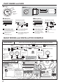
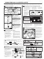
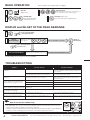
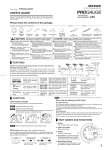
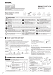
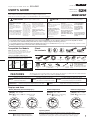
Triple Gauge for BMW 135 & 335 (52H-BM1 As of December, 2009 No.1)
52H-BM1
USER’S GUIDE
PLUG IN & SENSOR
EURO SPEC
Thank you for purchasing PIVOT “52H-BM1” for BMW 135 & 335.
Please read these instructions carefully before installing or using this device.
Please do not lose this user’s guide, as you will held liable for the cost of reissuing it.
Improper use or disregard of these warnings may
result in the injury or death of people.
CAUTION
Do not work in areas
where there is excessive
exhaust
Do not crush the
cable
Due to vehicle exhaust
emission poisoning or fire
may result in a damage to
humans.
Please securely fasten the
product to a stable place
It is very dangerous if, while
in use, the product falls off
and interferes with braking.
52H
HYBRID GAUGE
Do not operate while driving
Please be careful
that the cable does
not get crushed by
the seat rail or car
door steel plate, nor
cut by any sharp
steel plate as this
may cause a poor
connection or an
electric short
leading to fire or
other danger.
Operating or checking the
display during driving may
cause an accident; please use
with the utmost consideration
for safety.
Please be sure to store
bundle away all wires with
tape, etc...
It is very dangerous to pull
tangled wires by force or allow
tangled wires to interfere with
driving.
Improper use or disregard of these warnings may cause
injury to persons, damage the product and other things.
NOTE
This product is for DC12V
cars;
Do Not Use Chemical
Cleansers
Installation cannot be carried
out on cars with other
voltage batteries.
If the unit gets dirty do not
use chemical cleansers such
as thinner, benzene, or
alcohol; please wipe with a
soft cloth to remove any dirt.
Just after installation do
not exert any strong force
on the product
When double-sided tape is
used for an installation be
warned that when hot the
tape temporarily losses
adhesiveness.
Make sure to replace all
screws and parts to
their original place
Do not install the
product in a place
where it will cause
distraction
Do not install the product
in any place subject to
high temperature or any
place where water may be
splashed
Do not, in any manner,
process, take apart, or
make changes to this
product
1. The display will not be proper if the ECU being used is not the standard one or if a sub-computer is being used, even in compatible car models.
2. Cannot be used in combination with products that use another company’s diagnostic monitoring connectors.
3. For details about using in combination with other PIVOT products please see our Web Site at http://pivotjp.com/information/obd_conjunction-e.html.
4. During installation be sure to remove the minus cable from the battery.
Compatible Car Models
Check
the contents
BMW 135 (all models), 335 (2008.4- ※)
Due to minor changes in design, it may be impossible
to install in some models even though the year and
model may fit the specifications.
Boost
Gauge
Water Temp
Gauge
Exhaust Temp
Gauge
CAN Server
(with OBD2 Connector)
Boost Server
※About compatibility with model 335
If you are unsure of the year of your model car, please
check the figure below to confirm the position of the
terminals on the diagnostic monitor connector.
Fuse Power
Cable
Peak Switch
Gauge Cables
×3
Cut Connectors
×3
Male Wire
Crimp
Nylon Hose
(2m)
Terminals
Hook
Rubber Hose
(1m)
Compatible
T-Joint
Large ×2
Double-sided tape Cushion Tapes
Zip ties
×3
Small ×7
for Peak Switch
Triple Gauge Meter Hood
by 3D Design Corporation
User’s
Guide
Not Compatible
FEATURES
The 52H is an easy-to-install yet high-class triple gauge that provides you with all the most important data
for your BMW turbo engine. (Not for use with incompatible models)
Triple Simultaneous display of three types
of data: Boost, Water Temperature
Gauge and Exhaust Temperature
LED
Illumination
Conversion
Joint
Other Necessary Items
(sold separately)
Terminal
Hook
I-Joint
Peak Simultaneous display of peak values
after engine start.
Hold (The switch is a compact stick-on type)
Illumination by high contrast highly luminous white LED
For Water and Exhaust Temperature: Simple
Easy
Connection to the Diagnostic Monitoring Connector
Install For Boost: Easy Piping to Pressure Output
Stepping Motor
Drive
Stepping motor drive brings you a high-performance
display with no hunching or overshooting
Displays and Uses
Boost (Absolute pressure display※)
Water Temperature
Display 20 °C∼120 °C
Use ●Prevention of overheating
Display -100∼154 KPa
Use ●Check Boost ●For Eco-driving [Vacuum]
1
2
BOOST
STEPPING
GAUGE
0
STEPPING
GAUGE
Ex: 70Kpa
Peak Hold
Use
●Check Momentary Maximum Boost
●Check Highest Water Temperature
●Check Highest Exhaust Temperature
11
7
WATER
X100KPa
-1
9
120
80
BOOST
X100KPa
0
etc.
100
1
2
Display 200 °C∼1100 °C
Use ●Check air-fuel ratio
●Check Heating etc.
[Vacuum]
[Boost]
Exhaust Temperature
EXT
TEMP °C
TEMP °C
60
-1
STEPPING
GAUGE
X100
20
5
40
Ex: -40Kpa
STEPPING
GAUGE
3
2
Ex: 95˚C
Ex: 600˚C
Opening Demo
During the opening demo, the needle will move to minus several times, then to
the maximum value and finally to reading for each measurement item. (Due to product
characteristics the opening demo may not work simultaneously for all three gauges.)
1
PART NAMES and SIZE
●Gauge
■ SIZE
Bezel
[Unit : mm]
38
56.5
Dial
1
2
X100KPa
STEPPING
GAUGE
X100KPa
0
STEPPING
GAUGE
-1
[Front of the Gauge]
[Side of the Gauge]
●Boost Server
(View from Car Connection)
(View from Gauge Connection)
1
3
Gauge Output Coupler
Connect the Gauge Cables
from the Water Temperature and
Exhaust Temperature Gauges.
5
4
5
1-pin Coupler (Male side)
7
Power Cable
Connect the Gauge Cable
from the Boost Gauge.
6
1-pin Coupler (Female side)
6
7
8
Gauge Output Coupler
Connect to a Power Source
8
Peak Switch Coupler
Hose
For Boost Connection
Connect the 2-pin Coupler of
the Peak Switch
Connect the 1-pin Coupler of
the Peak Switch
Connect to get
Communication Signal
Not used.
※ The sensor is built into the
Boost Server, so there is no
need to purchase separately.
Connect the 1-pin Coupler of
the Fuse Power Cable
OBD2 Connector
(View from Car Connection)
(View from Gauge Connection)
2
3
4
2
[Top of the Server] 50
[Front of the Server]
●CAN Server
1
20
52
BOOST
Shows
the current
values.
-1
60
2
Needle
BOOST
0
1
BASIC WIRING and INSTALLATION EXAMPLE
BASIC WIRING
Please carry out wiring with the engine turned OFF and the key removed.
1-pin Coupler
OBD2
Connector
(※1)
Connector
(Wire Crimps)
Black
Red
1-pin Coupler
2
※1 When inserting,
make sure that the
OBD2 connector is
placed in the proper
direction.
Water
Temp
(IGN = 12V with key switch ON)
※Not as normal power source
Fuse
※Not used.
Diagnostic
Monitor
Connector
= Cut connector
(or soldering)
Connect to Power
Red
Black
3 4
6
CAN Server
Exhaust
Temp
3-pin
Coupler
Installation Example
7
8
Boost Server
Peak Switch
1
5-pin Coupler
Pressure Piping
2-pin Coupler
Boost
5
The 3-pin couplers can
be connected to any of
the three positions
5-pin Coupler
3-pin Coupler
Peak Switch
Install at Desired Place
Fuse Box
CAN
Server
Fuse
To IGN Fuse
※Not as normal
power source
※ Note that installing the
gauges here will result
in not being able to use
the standard ashtray
and cigarette lighter.
2
Fasten above
the footrest
Triple Gauge
Install to the Standard
Ashtray Position
Cover
Boost
Server
OBD2 Connector
To Diagnostic
Monitor Connector
WIRING METHOD and INSTALLATION
The following is just one example of a BMW 135 / 335 (2008 model, steering wheel on right). If your model is different and you are unsure of how to
connect please contact your dealer.
1 Connecting for Boost
3 Connecting the Fuse and OBD2 Connector
Standard
Vacuum Hose
Figure 1
↓To the inside
of the car
↑To the engine
room
Nylon Hose
Figure 2
Nylon Hose
I-Joint
Hose from the
boost server
Boost Server
Figure 3
Red
Boost
Server
CAN
Server
= Cut Connector
(or soldering)
Position
= 2nd column from the left
and 2nd row from the top
Number = 7, Capacity = 5A
① Cut the manifold vacuum hose.
(Figure 1)
② Insert a T-joint and connect the
various hoses and joints as
shown in figure 2.
③ Pull the nylon hose to the inside
of the car.
④ Using the I-joint, connect the
nylon hose to the boost server.
(Figure 3)
33
32
31
56 61
55 60
54 59
53 58
52 57
※ If you wish to get power
from a fuse other than
the 5A mini-fuse, please
purchase separately.
4
③ Pull the cables from each of the
gauges to foot area of the
driver’s seat. (At this point
make sure to mark the boost
gauge cable so as to
distinguish it from the other
two.)
11
12
13
14
15
21
22
23
24
25
26
27
28
29
30
39
38
37
42
41
40
46
45
-
49
48
47
KI. 30g
83
82
81
86
85
84
89
92
88
91
87
90
(Front of the fuse box)
⑤ Place a male connector on the black
wire that is leading from the black tube
on the Boost Server and using one of
the supplied connectors connect that
black wire to the black wire coming
from the OBD2 Connector.
Make sure that all hose and joint
connections are securely
fastened so as not to disconnect
or cause pressure loss. (Depending on
the conditions, it may be necessary to
take some action to prevent loosening
and disconnection of the various
connection points.)
36
35
-
16
17
18
19
20
6
7
8
9
10
1
2
3
4
5
BMW 135 / 335 (2008 Model,
steering wheel on right)
⑥ Remove the cover from the
diagnostic monitor connector found
at the bottom right of the driver’s
seat and fully insert the OBD2
connector that is coming from the
CAN Server.
Installing the Peak Switch and Fastening the Servers
① Insert the 2-pin coupler from
the peak switch into the Boost
Server and connect the 1-pin
coupler to the 1-pin coupler
coming from the CAN Server.
2 Installing the Meter Hood
② Fasten the meter hood
according to directions in the
User’s Manual from 3D Design.
Figure 4
【REFERENCE 1】
Zip tie (Large)
① Remove the undercover from
beneath the steering wheel.
Fuse
62
63
64
65
66
Conversion
Joint
1-pin Coupler
Black
67
68
69
70
71
Rubber Hose
1. Be sure install the boost
server on the inside of
the car. (Not in the
engine room)
2. Stretch the hose that comes
out from the boost server but
do not pull it off.
Red
50
Upper Mount
T-Joint
④ Using one of the
supplied “cut
connectors” (or by
soldering) connect the
red wire from the CAN
Server that was
connected in ③ to the
red wire of the Boost
Server. (Figure4)
72
73
74
75
76
77
78
79
80
← Front
Vacuum Hose
(cut)
③ Connect the CAN
② Pull out the IGN fuse
Server to the 1-pin
and replace it with the
coupler or the fuse
supplied fuse power
power connector.
connector making sure
the wire is at the top.
① Remove the glove box hook or
the rear cover of the glove box
so as to be able to see the
interior fuse box. (See your
car’s User’s Manual for details)
Cut
④ As you pull the gauge cables
through the meter hood, return
the center console to its original
position.
Server
② Position the Peak Switch in
the desired place and affix
with double-sided tape.
Standard Cable
⑤ Affix the cushion tape that comes
with the gauges and insert each
cable’s 5-pin coupler into each
gauge.
③ Using the large lock ties that
came with the servers, bundle
the standard cables and wires
above the footrest as shown
in figure 5.
Foot rest
⑥ Fix the gauges by pressing them
into place in the meter hood.
(Adjust the gauges to a position
which makes them easy-to-read.)
Brake
Figure 5
④ Bundle up all loose wires and
replace everything to its
original position.
【REFERENCE 1】Notes about using the OBD2 connector
If you are unable to get power from the fuse box, please wire
directly to IGN (12V with key in ON position).
IGN
CAN
Server
※Not as normal power source
1-pin Coupler
Do not pull on the wires
when trying to remove the
connector; the wires may
become disconnected.
If you unable to get a grip on the
distended portions
Fuse
Red
Make sure to grip the
distended portions
when pulling it out or
inserting it.
= Cut Connector
(or soldering)
Cut
In such cases,
use a lock tie to
push or pull the
connector.
With some car models it
may be difficult to get a
good grip on the connector.
【REFERENCE 3】How to use the connectors
at times like this
How to use the cut connectors
When use in conjunction with the PIVOT’s 3-drive series
① Disconnect the OBD2
connector from the diagnostic
monitor connector on the car.
② Cut the wires from the
connector.
③ Place a male connector on the
red wire and connect with a
cut connector to the red wire
coming from the CAN Server.
④ Using a cut connector (or by
soldering) connect the black
wire to the black wire coming
from the Boost Server.
⑤ Connect the OBD2 connector
to the diagnostic monitor
connector.
Red
OBD2
Connector
Cut
3-drive
Black
OBD2 Connector
Red
Boost
Server
Black
Black
Red
2
Peel off about 10mm
of the vinyl cover at
connection.
Peel off about 10mm of
the vinyl cover at the end
of the product’s wire.
3
4
Twist the
uncovered
wires.
Close tightly
with cut
connector.
※ Use a crushing tool to press
the cut connector, if you do
not have such a tool, use
pliers or such to fold and
crush the connector together
for a secure contact.
※ After covering, make sure to
insulate properly with vinyl
tape.
How to use the male wire crimps
Red
3-drive
CAN
Server
1
Black
1 Peel off about 10mm
2 Bend the outside wires
3 Pull the wire through
4 Place the wire onto
5 Crush the center tabs of
6 Crush down the outer
of vinyl covering from
the tip of the wire.
the cover.
= Cut Connector
(or Soldering)
= Connector
(Wire Crimps)
the crimp down to hold
the center of the wire.
around the core to make
the wire thicker.
the crimp.
tab of the crimp over
the vinyl covering.
※ Note; Securely connect the male and female crimps, making sure
to twist the male cover firmly into the female cover.
3
BASIC OPERATION
1
2
Key ON
START
STOP
EN
Basic operation from engine start to stopping.
GINE
Opening Demo
(Due to product characteristics the opening demo may
not work simultaneously for all three gauges.)
(Engine start)
START
Real Display
3
Each gauge will display
actual measurements.
4
Key OFF (Engine stop)
-1
The needle stops at the key OFF position.
DISPLAY and RE-SET OF THE PEAK READINGS
1
Press the Peak Switch
during Real Display
2
Display
Peak Readings
Simultaneous display
of all 3 gauges
Return to
Real Display
With no operation 5 seconds
Press the Peak Switch
for 3 Seconds
3
Re-set Peak Readings
All 3 gauges are simultaneously re-set.
Will return automatically after re-set
※Peak readings are reset when the key is turned OFF.
TROUBLESHOOTING
Trouble
Don’t operate when the engine is started
(all three).
Possible Causes
Possible Solutions
Poor connection of the OBD2 connector or IGN fuse.
Please check the connections for both the OBD2
connector and IGN fuse to make sure they are proper and
well connected.
If wiring has been direct to power the red wire may have
been improperly wired or there is a poor connection.
Please check the connections for the red wire to make
sure it is proper and well connected.
Boost Gauge doesn’t operate when engine
is started.
Either the black and red wires on the boost server are
misconnected or there is a poor connection.
Please check the connections for both the red and black
wires of the boost server to make sure they are proper
and well connected.
When engine is started, the opening demo
comes on but the water temperature and
exhaust temperature gauges don’t work.
The temperature is not high enough yet to be displayed.
Please run the car until temperatures reach display level.
The OBD2 Connector is poorly connected.
Please re-insert the OBD2 connector.
The unit has been installed into an incompatible car model.
Please check the list of compatible car models.
When engine is started, the opening demo
comes on but the boost gauge doesn’t work.
There is a poor hose connection or a hose is being
compressed.
Please check the boost hose connections.
The boost pressure display is different from
the standard or other gauges.
This product’s boost gauge reads relative pressure and may differ from a gauge using absolute pressure.
Even if I press the Peak Switch, the peak
value is not displayed.
The Peak Switch connection is poor.
Please check the Peak Switch connections.
The auto-power window function and/or
other electronic devices are re-set.
The may occur because the minus terminal of the car
battery was disconnected.
Please re-connect the minus terminal and follow re-setting
instructions in User’s Manuals for any affected devices.
NOTE
How to Turn Off the CHECK Lamp
If the CHECK lamp comes on due to some operational mistake, please follow the directions below to turn it off.
① Under normal conditions, start and stop the engine several times.
② If that does not turn off the lamp, disconnect the cable minus from terminal of the battery for about 10 minutes.
③ If that does not turn off the lamp, please consult your local car dealer and have them turn it off.
4
PIVOT CORPORATION
87-3, Shimookada Okada, Matsumoto-shi, Nagano, 390-0313 Japan
Check Lamp
is ON
TEL0263-46-5901
http://pivotjp.com/