1
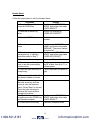
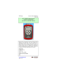
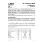
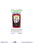
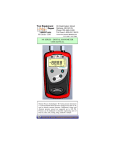
User’s Manual 9R122-A June, 2010 M203 Altimeter / Indicated Air Speed Tester USER’S MANUAL The Meriam Process Technologies (Meriam) M203 Altimeter / Indicated Air Speed Tester is a microprocessor based pressure sensing device used to measure pressure 0-900 millimeters (mm) Hg relative to absolute zero. The handheld is NIST traceable. When used in Pressure Measure Mode, pressure can be displayed in a variety of engineering units. Select the ALT / IAS engineering unit and the M203 converts to Altitude Mode for checking altimeter instruments. Pressing the TARE button from Altitude Mode changes the M203 to Air Speed Mode for checking air speed instruments. A timed leak test function is available for Pressure, Altitude and Air Speed Measure Modes. Other features include a Min/Max capture, selectable damp rates and field re-calibration. 1.800.561.8187 www. .com [email protected] Safety Information Failure to follow all instructions could result in injury. Read, understand and follow all safety warnings and instructions provided with this product. Also, meet or exceed your employer’s safety practices. In no event shall Meriam be liable for any indirect, special, incidental, consequential or punitive damages or for any lost profits arising out of or relating to any services provided by Meriam or its affiliates. It is not possible for Meriam to identify all foreseeable uses/misuses, therefore all persons involved in commissioning, using or maintaining this product must satisfy themselves that each intended application is acceptable. Safety Warnings The table below defines the safety symbols, signal words and corresponding safety messages used in the manual to identify potential hazards and are intended to warn persons about hazards that could result in personal injury or equipment damage. h This is the Read Instruction Manual symbol. This symbol indicates that you must read the instruction manual. This is the Safety Alert symbol. This symbol indicates a WARNING. Warnings alert you to actions that can cause personal injury or pose a physical threat. Please read these carefully. This is the Safety Glasses symbol. This symbol indicates that you must wear approved safety glasses during the task. This is the Safety Gloves symbol. This symbol indicates that you must wear approved safety gloves during the task. Indicates a potentially hazardous situation which, if not avoided, will result in death or serious injury. Indicates a potentially hazardous situation which, if not avoided, could result in death or serious injury. Indicates a potentially hazardous situation which, if not avoided, could result in minor or moderate injury. Indicates information essential for proper product installation, operation or maintenance. Information in this document is subject to change without notice. Check the Meriam web site (www.meriam.com) for the latest manual revision. 1.800.561.8187 www. .com [email protected] Table of Contents Certification/Safety/Warnings .......................................................1 User Interface ...............................................................................2 1. Keypad Functions ...................................................................2 ON/OFF & BACK KEY ................................................................2 MIN/MAX & UP KEY...................................................................2 TARE & DOWN KEY ..................................................................2 PRGM & ENTER KEY.................................................................3 BACKLIGHT KEY..........................................................................3 2. Zeroing the Manometer ...........................................................4 3. Program Mode ......................................................................8 Units Select ..................................................................................9 ALT / IAS (Altitude / Indicated Air Speed) Mode..................................10 Damp Rate Select ........................................................................12 User Info Select (Accuracy, SW version, Mfr date, SN).........................13 Auto Shut-Off...............................................................................14 Lockout Select..............................................................................15 Header Name ..............................................................................16 Contrast Select............................................................................17 Data Logging ...............................................................................18 Leak Test....................................................................................19 Re-Calibration..............................................................................20 RE-CALIBRATION – 1 Point EDIT and START...................................21 RE-CALIBRATION – 5 Point EDIT....................................................22 RE-CALIBRATION – 5 Point START ................................................23 RE-CALIBRATION – Restore Factory Defaults ...................................24 Specifications...............................................................................25 Changing the Batteries ................................................................26 Service and Calibration................................................................28 1.800.561.8187 www. .com [email protected] Certification/Safety/Warnings User’s Manual 9R122-A June, 2010 Fire/Explosion Hazard. This instrument is not intrinsically safe. DO NOT use in areas that may contain flammable gas or vapors, combustible dusts or ignitable fibers where an unintended spark can cause a fire/explosion. Do not exceed the Pressure Limits listed in the Specifications section of this manual. Failure to operate within the specified pressure limit could result in minor or moderate injury Substitution of components may impair operation and safety. Disconnect power before servicing. The product should not be powered with a combination of new and old batteries. The product should not be powered with a combination of batteries from different manufacturers. User must use a wrench on the pressure manifold when installing user’s 1/8” NPT fitting. Do not tighten the fitting without using a wrench on the pressure manifold. Failure to use a wrench on the manifold will damage the plastic enclosure and void warranty No torque should be applied to the manifold with respect to plastic enclosure. 1.800.561.8187 1 www. .com [email protected] User Interface 1. Keypad Functions ON/OFF & BACK ◄ KEY Turns the manometer on and enters the unit into the Measure Mode. Pressing the key while in the Measure Mode turns the unit off. It also serves as a backspace key when editing in the Program Mode. The ◄ key takes the user out of a programmable register without changing the previous setting. Pressing this key repeatedly will return the user to the Measure Mode and then shut off the manometer. MIN/MAX & UP ▲ KEY In the Measure Mode activates the Min/Max function of the manometer. When activated the minimum value is displayed on the upper left of the display and the maximum value on the upper right. This key also deactivates and resets this function. The ▲ key is used to scroll through the programmable registers when the unit is in the Program Mode. Once a programmable register is selected the ▲ key can be used to edit that register. TARE & DOWN ▼ KEY In the Pressure Measure Mode, toggles on/off the Tare function. The Tare function nulls the applied pressure and sets the display value to “0”. With Tare activated, the letter “T” appears in the lower left of the display. In the ALT / IAS Measure Mode (selected from Program Mode under Units Select menu), the Tare button toggles between ALTITUDE function and AIR SPEED function. The ▼ key is used to scroll through programmable registers when the unit is in Program Mode. Once a programmable register is selected the ▼ key can be used to edit that register. 2 1.800.561.8187 www. .com [email protected] PRGM & ENTER ► KEY Puts the manometer into the Program Mode from the Measure Mode. When in the Program Mode, pressing this key selects the programmable register to be edited (with prompt for password if Lockout is set). After the register has been edited, pressing the PRGM key enters the new setting into the manometer’s non-volatile memory. This key also acts as a forward space ► key when editing user inputs such as the header name. BACKLIGHT KEY The BACKLIGHT key, represented by the standard light bulb symbol, toggles the display backlight between on and off. The backlight consumes additional battery energy. Turn the backlight off, when it is not needed, to optimize battery life. 3 1.800.561.8187 www. .com [email protected] 2. Zeroing the Manometer The M203 Precision Smart Manometer is a stable and precise instrument. However, on occasion the M203 should have a new zero taken. This is done to remove zero drift that can occur since the manometer was last zeroed. The M203 can be zeroed only if the new applied zero is within ±1% FS of the original factory calibration zero. This prevents accidental zeroing at atmospheric pressure or other relatively high pressures. If outside this limit a “ZERO RANGE ERROR” message appears and the manometer will not zero. The M203 provides three mechanisms for re-zeroing: 1. Referenced to Absolute Zero: This traditional and preferred method takes a “snapshot” of the measured pressure when a vacuum of less than 100 microns Absolute is applied to the sensor. 2. Factory Zero: This method restores the calibration curve to the original zero taken at the factory. Note that this feature is intended for comparison purposes, and should not be used for real pressure measurement, as any zero-drift since shipment will not be accounted for. 3. User-Adjusted Zero: This method allows the user to enter any pressure value when a known reference is applied (for example, the local barometric pressure reading). The manometer will compare its actual measured value with the entered value, and calculate a new zero reference based on the offset. 4 1.800.561.8187 www. .com [email protected] 1. To zero the manometer using Referenced to Absolute Zero, start with the unit turned OFF and use the following keystroke sequence: Keystroke 1. Press ON/OFF button. 2. Connect the M203 to a vacuum source capable of 100 microns absolute or less. 3. Pull a full vacuum 4. Press MIN/MAX and TARE keys at the same time. (See Figure 1 below.) 5. Press the PGRM key. Figure 1 Display The display briefly shows the header name and full scale range in the last engineering units selected. The manometer then goes into the Measure Mode showing the pressure and engineering unit. Display should read close to zero. (See note on next page) Top line of display reads “ZEROING SOURCE:” Bottom line of display reads “REF TO ABS ZERO” Top line of display reads “ZERO IN PROGRESS” while bottom line counts down from 9. Zeroing is complete when unit returns to Measure Mode. NOTE: The M203 can be zeroed only if the new applied zero is within ˜ 1% FS of the original factory calibration zero. If outside this limit a “ZERO RANGE ERROR” message appears and the manometer will not zero. Contact the factory for support in this case. 5 1.800.561.8187 www. .com [email protected] 2. To zero the manometer using Factory Zero, start with the unit turned ON and in Measure Mode. Then use the following keystroke sequence: Keystroke 1. Press MIN/MAX and TARE keys at the same time. (See Figure 1 above.) 2. Press ▲ or ▼ arrow key until desired zero function is shown on the bottom line. 3. Press the PRGM key. Display Top line of display reads “ZEROING SOURCE:” Bottom line of display reads “REF TO ABS ZERO” Bottom line of display reads “FACTORY ZERO” Zeroing is complete when unit returns to Measure Mode. The Factory Zero feature is intended for comparison purposes only. Factory Zero should not be used as a reference for actual pressure measurement because zero-drift occurring after shipment would not be accounted for. Use Referenced to Absolute Zero or User-Adjusted Zero options when re-zeroing is necessary. 3. To zero the manometer using User-Adjusted Zero, start with the unit turned ON and in Measure Mode. Then use the following keystroke sequence: Keystroke Display 1. Apply a known, accurate pressure source. This may be true atmospheric pressure from a reference barometer 6 1.800.561.8187 www. .com [email protected] 2. Press MIN/MAX and TARE keys at the same time. (See Figure 1 above. Top Line of display reads “ZEROING SOURCE:” Bottom line of display reads “REF TO ABS ZERO” 3. Press ▲ or ▼ arrow key until desired zero function is shown on the bottom line. Bottom line of display reads “USER ADJ. ZERO” 4. Press the PRGM key. Top line of display shows the current non-zero compensated pressure value. Bottom line of display shows the same value, along with the engineering unit. 5. Press any of ▲ or ▼ arrow key or the PRGM key to begin editing. Top line of display continuously updates. Bottom line of display data is ready for editing; the first character location is blinking. Example: set current pressure value to 29.5 in Hg @ 0° C Abs. 6. Press the ▲ or ▼ arrow key to set the first digit to 0. Current: xxx.xx 0xx.xx INHG Using the ▲ arrow key, the character sequence is 0 – 9, (-) negative, (.) decimal point. The (-) sign is used if your location is below sea level. 7. When the User Adj. Value is correct press the PRGM key. Cursor flashes to the right of “0”. 7 1.800.561.8187 www. .com [email protected] If an error is made use the back space ◄ key to move the cursor back to the incorrect digit. Press the UP ▲ or DOWN ▼ arrow keys to correct the value, 8. Continue this process until the display reads as shown at right. 9. Press the PRGM key to enter the final value. Current: xxx.xx 029.50 INHG Zeroing is complete when unit returns to Measure Mode. Note that the User Adjusted Zero feature will not accept entries in altitude units (FEET or METERS). When the current engineering unit is FEET, the User Adjusted Zero function will automatically prompt for an entry in Inches of Mercury @ 0º C. When the current engineering unit is METERS, the User Adjusted Zero function will automatically prompt for an entry in Millimeters of Mercury @ 0º C. 3. Program Mode The Program Mode is used to configure the manometer for Measure Mode operation. After the PRGM key is pressed in Measure Mode, the top line of the display reads “PROGRAM MODE”. The bottom line reads “UNITS SELECT”. Press the ▲ or ▼ arrow keys to scroll through the Program Mode to the desired register. The configurable registers found in the Program Mode are Units Select, Damp Rate Select, User Info Select, Contrast Select, Data Logging, Leak Test and Exit. Press the PRGM key to select any of these configurable registers. The manometer can be put into Program Mode at any time during Measure Mode operation by pressing the PRGM key. If Lockout is set, the correct code must be entered when prompted (see the User Info / Lockout section of this manual for more information on Lockout). 8 1.800.561.8187 www. .com [email protected] Units Select The standard units available on the M203 are: Inches of Mercury at 0° C (in Hg @ 0° C) (absolute) Millimeters of Mercury at 0° C (mm Hg @ 0° C) (absolute) PSI (absolute) Mbars (absolute) Bars (absolute) kPa (absolute) Torr (absolute) ALT / IAS - selecting this unit gives access to English units. (knots, MPH and Feet) or Metric (km/h and Meters) To change the engineering units the manometer should be “ON” and in Measure Mode. Then follow these steps: Keystroke 1. Press the PRGM key. Display Top line reads “PROGRAM MODE” and bottom line reads “UNITS SELECT”. Top line reads “UNITS SELECT” and bottom line shows current engineering unit. Engineering units on bottom line of display change. 2. Press the PRGM key. 3. Press the ▲ or ▼ arrow key until desired engineering unit is displayed 4. Press the PRGM key to select the engineering unit. Top line reads “PROGRAM MODE” and bottom line reads “UNITS SELECT”. Bottom line reads “EXIT”. 5. Press the ▼ arrow key 6. Press the PRGM key. Display returns to Measure Mode in new engineering unit. 9 1.800.561.8187 www. .com [email protected] ALT/ IAS (Altitude / Indicated Air Speed) Mode The model M203 is capable of displaying altitude (feet or meters based on “U.S. Standard Atmosphere 1962” tables) and air speed (knots, MPH or km/h). The ALT / IAS Mode is selected from Program Mode in the Units Select menu. Once ALT / IAS Mode is selected, the M203’s default measurement is altitude. Pressing the “Tare” key nulls the prevailing barometric pressure and converts the display to air speed indication. To revert back to altitude the “Tare” key is toggled again. To set up the M203 for ALT / IAS Mode use the following steps: Keystroke 1. Press the PRGM key. Display Top line reads “PROGRAM MODE” and the bottom line reads “UNIT SELECT”. 2. Press the PRGM key. Top line reads “UNITS SELECT” and bottom line shows current engineering unit. Top line reads “UNITS SELECTED” and bottom line reads “ALT / IAS”. 3. Press the ▲ or ▼ arrow key until “ALT/ IAS” is displayed. 4. Press the PRGM key. Top line reads “UNITS SELECT” and bottom line reads “ENGLISH”. Top line reads “UNITS SELECT” and bottom line reads “KNOTS”. Note: the altitude unit “FEET” is associated with Knots. 5. a. If ENGLISH units are desired, press the PRGM key. (For METRIC units, Go To Step 6.) b. If KNOTS unit are desired, Go To Step 7. (For MPH units, Go To Step 5.c. 5. c. If MPH units are desired, press the or arrow key until “MPH” is displayed. Top line reads “UNITS SELECT” and bottom line reads “MPH”. Note: the altitude unit “FEET” is associated with MPH. 5.d. Go To Step 7. 10 1.800.561.8187 www. .com [email protected] 6. If METRIC units are desired, press the ▲ or ▼ arrow key Top line reads “UNITS SELECT” and bottom line reads “METRIC”. Units are set to METERS and km/h. 7. Press the PRGM key. Top line reads “PROGRAM MODE” and bottom line reads “UNITS SELECT”. 8. Press the ◄ key. Manometer returns to Measure Mode displaying Altitude. 1. Altitude is the default measurement when ALT /IAS Mode is active. 2. If ALT / IAS Mode was active upon manual or automatic shut off, ALT / IAS Mode will be restored upon cycling power and altitude will be displayed. 3. When the M203 is displaying air speed and power is turned off (manually or automatically), Program Mode is entered, or the Tare key is pressed, the unit will be returned to altitude display once power is cycled or the unit is returned to Measure Mode. This is a feature designed to prevent errors in air speed measurement, necessary because of the tare function employed on barometric pressure to arrive at air speed measurements. Barometric pressure fluctuates with changes in weather conditions. Reverting to altitude measurement upon powering down, entering Program Mode or pressing the Tare button forces a new tare value to be taken prior to each air speed measurement session. 11 1.800.561.8187 www. .com [email protected] Damp Rate Select Adjustable exponential type damping is available to steady the display when measuring pulsating pressures. The M203 has a range of damping rates; 0.1, 0.2, 0.5, 1, 2, 5, 10, or 25 seconds. Damping is done by averaging new data from the pressure sensor against previously collected data. The microprocessor collects data from the sensor every 0.1 seconds. The display updates every 0.5 seconds, showing the current 0.1 second pressure reading. When set at 25 seconds, the display updates every 0.5 seconds with the average of the previous 25 seconds readings. Therefore, it takes up to 25 seconds from the time pressure is applied until the manometer displays the full scale applied pressure. Min/Max display updates every 0.1 seconds. To set the damp rate: Keystroke 1. Enter Program Mode by pressing the PRGM key. 2. Press the ▲ key. 3. Press the PRGM key. 4. Press the ▲ or ▼ keys until the desired damp rate is displayed on the bottom line 5. Press the PRGM key. Display Top line reads “PROGRAM MODE”. Bottom line reads “UNITS SELECT”. Bottom line reads “DAMP RATE SELECT”. Top line reads “DAMP RATE SELECT”. Bottom line shows current value. Bottom line shows damp rate settings in seconds. 6. Press the ▼ key. Top line reads “PROGRAM MODE”. Bottom line reads “UNITS SELECT”. Bottom line reads “EXIT 7. Press the PRGM key. Returns to Measure Mode. 12 1.800.561.8187 www. .com [email protected] User Info Select (Accuracy, SW version, Mfr date, SN) The User Info Select registers are designed to provide the user with information on the hardware and software in the manometer. This register provides read only information on the sensor’s accuracy, software version, date of manufacture and serial number. It also allows the user to edit the Auto Shut-Off, Lockout and StartUp Header Name features. To access the User Info Select registers, follow the steps below. To configure a User Info Select register, follow the steps shown on the following page. Keystroke 1. From the Measure Mode press the PRGM key. 5. Press the ▲arrow key Display Top line reads “PROGRAM MODE” and bottom line reads “UNITS SELECT”. Bottom line changes to “USER INFO SELECT”. Bottom line shows accuracy Software version no. shown. Manufacture date shown. 6. Press the ▲arrow key. See instructions to set AUTO SHUT-OFF later in this manual. Top line reads “AUTO SHUT OFF” and bottom line reads “ENTER TO SELECT”. 7. Press the ▲ arrow key. Bottom Line shows Serial No. Top line reads “LOCKOUT CODE” and bottom line reads “ENTER TO SELECT”. Top line reads “HEADER NAME” and bottom line reads “MERIAM”. The cursor flashes at bottom left. Top line reads “PROGRAM MODE” and bottom line reads “USER INFO SELECT”. 2. Press the ▲ arrow key twice. 3. Press the PRGM key. 4. Press the ▲arrow key. 8. Press the ▲ arrow key. See instructions for using LOCKOUT later in this manual. 9. Press the ◄ arrow key. See instructions for editing the Header later in this manual. 10. Press the ◄ arrow key to go back to “USER INFO SELECT” screen. 13 1.800.561.8187 www. .com [email protected] Auto Shut-Off Enabling the Auto Shut-Off feature allows the manometer to turn itself off after a user selected period of keypad inactivity. Selectable options include DISABLED, 10 Minutes (which is the factory shipped default), 20 Minutes, 30 Minutes, 45 Minutes and 60 Minutes. Disabling this feature limits the manometer to being turned off by using the ON/OFF key only. To configure auto shut-off follow these steps: Keystroke 1. Follow steps 1-6 in the user Info Select table. 2. press the PRGM key, then the up or down arrow keys until the desired shut-off time is shown. Display Top line reads “AUTO SHUT-OFF” and bottom line reads “ENTER TO SELECT”. Top line reads “AUTO SHUT-OFF” and bottom line toggles to “DISABLED”, “10”, “20”, “30”, “45” and “60” minutes . 3. Press the PRGM key. Desired Auto Shut-Off time is selected, top line reads “AUTO SHUT-OFF” and bottom line reads “ENTER TO SELECT”. 4. Press the left arrow key three times. Returns to Measure Mode. The “Auto Shut-Off” timer is suspended during Data Logging and Leak Test sessions to prevent accidental loss of information. Auto Shut-Off is re-instated after completion of Data-Logging or Leak Test sessions. 14 1.800.561.8187 www. .com [email protected] Lockout Select Enabling the Lockout feature prevents unauthorized users from making changes to the configuration of the manometer. To enter the Program Mode, the user must first enter the “password” (two-digit Lockout Code) within approximately 40 seconds when prompted. Failure to enter the correct two digit code within approximately 40 seconds will return the unit to Measure Mode. Any two-digit numeric code can be programmed. The factory Lockout Code of 00 (which is the default as shipped from the factory) disables the Lockout. To set the Lockout Code follow these steps: Keystroke 1. From the Measure Mode press the PRGM key. If the Lockout is set, enter the correct “password” when prompted. 2. Press the up arrow key twice. Display Top line reads “PROGRAM MODE” and bottom line reads “UNITS SELECT”. 3. Press the right arrow key then the up arrow key four times. Top line reads “LOCKOUT CODE” and bottom line reads “ENTER TO SELECT”. 4. Press the right arrow key, then press the up arrow keys to change the first digit. Press the right arrow key to proceed. Bottom line shows the old Lockout Code. The cursor flashes at the first position while the value is changed, the cursor moves to the right position once the right arrow key is pressed. Top line reads “LOCKOUT CODE” and bottom line reads “ENTER TO SELECT”. 5. Press the right arrow key when the desired code is set. Lockout is activated. 6. Press the left arrow key twice Bottom line reads “USER INFO SELECT”. Returns to Measure Mode. 15 1.800.561.8187 www. .com [email protected] Header Name Follow the steps below to edit the Header Name. Keystroke 1. From the Measure Mode press the PRGM key. 2. Press the up arrow key twice. Display Top line reads “PROGRAM MODE” and bottom line reads “UNITS SELECT”. Bottom line changes to “USER INFO SELECT”. 3. Press the PRGM key. Bottom line shows serial number. 4. Press the up arrow key five times. 5. If header is correct press backspace key. If editing is desired proceed to Step 7. 6. Press the left arrow key. Top line reads “HEADER NAME” and bottom line reads “MERIAM”. The cursor flashes at bottom left. Top line reads “PROGRAM MODE” and bottom line reads “USER INFO SELECT”. Returns to Measure Mode 7. Press the up or down arrow keys to set the correct alphanumeric value, 8. Press the right arrow key to accept entry, Displays a number between 0 and 9, a letter from A to Z, / or a blank space. Cursor advances one space to right. 9. Repeat steps 8 and 9 until the desired Header is shown. 10. If an error is made press the back arrow key until the cursor is over the incorrect value. Follow Step 8 to correct. Press the right arrow key to advance the cursor without changing the values. 11. When the Header is complete press the PRGM key until header accepted. 12. Press the left arrow key. Top line reads “PROGRAM MODE” and bottom line reads “UNITS SELECT”. Returns to Measure Mode. 16 1.800.561.8187 www. .com [email protected] Contrast Select The Contrast Select register allows the user to adjust the character contrast of the LCD display to provide the best visibility for the ambient light conditions. To adjust the contrast, follow these steps: Keystroke Display 1. From the Measure Mode press the PRGM key. Top line reads “PROGRAM MODE” and bottom line reads “UNITS SELECT”. 2. Press the ▲ key three times. Bottom line reads “CONTRAST SELECT”. 3. Press the PRGM key, Top line reads “CONTRAST SELECT”. Bottom line shows a numerical value. 4. Press the ▲ or ▼ keys to increase or decrease the contrast value. A low number gives maximum contrast and a high number gives minimum contrast. LCD lightens or darkens depending on the value set. 5. Press the PRGM key. Top line reads “PROGRAM MODE” and bottom line reads “UNITS SELECT”. Returns to Measure Mode. 6. Press ◄ key. If an error is made during the contrast adjustment, pressing the ◄ key returns the display to the previous contrast setting 17 1.800.561.8187 www. .com [email protected] Data Logging Data Logging can be used to record pressure measurements. Two record modes are supported: automatic and manual. In automatic mode, a pressure value is captured every 5 seconds for 20 minutes, resulting in 240 stored values. In manual mode, a pressure value is captured each time the PRGM key is pressed up to 240 values. The data collected during a logging session can be viewed upon completion. Keystroke Display 1. From the Measure Mode, press the PRGM key. Top line reads “PROGRAM MODE” and bottom line reads “UNITS SELECT”. 2. Press the ▲ key five times. Bottom line reads “DATA LOGGING”. 3. Press the PRGM key. Top line reads “DATA LOGGING” and bottom line reads “RECORD”. 4. Press the PRGM key. Top line reads “RECORD MODE” and bottom line reads “AUTO” or “MANUAL”. 5. Press the PRGM key at Top line reads AUTO to start automatic “RECORDING X” and bottom logging or at MANUAL to start line reads “XX.XX UNITS”. manual logging mode. AUTO records value every 5 seconds. Manual records value each time PRGM key is pressed. 6. To stop recording values at Top line reads “DATA any time, press the ◄ key. LOGGING” and bottom line reads “RECORD”. 7. To access recorded values, Top line reads “DATA press the ▲ key. LOGGING” and bottom line reads “VIEW”. 8. To view recorded values, Top line reads “DATA LOG: 1” press the PRGM key. and bottom line displays the value. Continue pressing the ◄ key to view all values. 9. Press the ◄ key 3 times. Returns to Measure Mode. The Auto Shut-Off” timer is disabled for Data Logging sessions. Be sure to end the session to re-enable the Auto Shut-Off timer. 18 1.800.561.8187 www. .com [email protected] Leak Test The Leak Test feature allows the user to determine the leak rate in the pneumatic system being monitored. Once configured, Leak Test monitors the measured pressure, altitude or air speed over time and displays the leak rate in units per minute at the conclusion of the test. The maximum configurable leak test period is 1440 min (1 day). Pressing any key during the leak test aborts the test. To enable Leak Test follow these steps: Keystroke 1. From the Measure Mode, press the PRGM key. 2. Press the ▼ key twice. Display Top line reads “PROGRAM MODE” and bottom line reads “UNITS SELECT”. Bottom line reads “LEAK TEST” 3. Press the PRGM key. Top line reads “LEAK TEST” and bottom line reads “CONFIGURE”. 4. Press the PRGM key. Top line reads “Leak Test Period” & bottom “X.X MIN”. 5. Use the ▲, ▼ & ► keys to input test period 6. Press the PRGM key. Bottom line reads desired period; Ex. “20.0 MIN”. Top line reads “LEAK TEST” and bottom line reads “CONFIGURE”. 7. Press the ▲ key once. Top line reads “LEAK TEST” and bottom line reads “PRGM TO START”. Top line displays MIN/MAX pressure values at left/right. Bottom line reads the current pressure value and units. 8. Press the PRGM key. 9. Press the PRGM key. At end of test period, top line displays the leak rate in units per minute. Bottom line shows the current pressure reading. Return to Measure Mode The “Auto Shut-Off” timer is disabled for Leak Test sessions. Be sure to end the session to re-enable the Auto Shut-Off timer. 19 1.800.561.8187 www. .com [email protected] Re-Calibration The Manometer can be re-calibrated in the field for zero, span, and linearity. The proper primary standards must be available prior to calibrating the Manometer. These standards should meet the accuracy requirements for your company or industry. Meriam Process Technologies follows the guidelines established by ANSI / NCSL Z540- 1-1994 which requires that the primary standard be four times more accurate than the unit under test. The re-calibration is not intended to replace the Factory Laboratory Calibration Procedure. It is intended to correct the curve fit if the actual sensor characteristics change slightly over time. For sensors up to 200 PSI, Meriam recommends a ±0.0015% of reading deadweight tester. If calibrating using inches or millimeters of mercury, be sure to match the reference temperature of mercury in both the M203 and the deadweight tester. The reference temperature for these units in the M203 is 0º C. 1-point (within upper 50% of Full Scale), 5-point (nominal values of 0%, 25%, 50%, 75% & 100% of Full Scale), and restore factory default re- calibration options are offered. For the 5-Point re-calibration, points 2, 3 and 4 can be adjusted within 1% of reading around the nominal values. Point #5 can be adjusted within -1% of reading around nominal. Point #1 is fixed at zero. For example: for a 900 mm Hg Abs sensor (nominal 17 PSIA), Point # 2 (25%) can be edited form 216 to 234 mm Hg Abs. Point #5 (100%) can be edited from 891 to 900 mm Hg Abs. The unit can only be re-calibrated if the calibration points are within 5 times the accuracy of the original factory calibration (e.g., @ 0.05% accuracy, the point limit is 0.25% of Full Scale). If the re-calibration procedure generates a new value outside this limit the procedure will fail. In this case the unit would need to be returned to the factory for service. Once a re-calibration has been performed (either 1-point or 5- point) the unit will continue to allow future re-calibrations only with that type of re-calibration. In order to enable the other re- calibration type, the user must first restore the recalibration data to the factory defaults. 20 1.800.561.8187 www. .com [email protected] RE-CALIBRATION – 1 Point EDIT and START To perform a 1-point re-calibration, apply a pressure between 50% and 100% of Full Scale and then follow these steps: Keystroke 1. With unit OFF, press and hold the MIN/MAX key, turn the unit on by pressing the ON/OFF key, then release MIN/MAX. Display Top line reads “RE-CAL”. Bottom line reads “EDIT”. 2. Press the up arrow key until “START” is displayed on the bottom line. Top line reads “RE-CAL”. Bottom line reads “START”. 3. Press the PRGM key. Top line reads “RE-CAL START”. Bottom line reads “1POINT”. 4. Press the PRGM key. Top line reads “CAL POINT” and bottom line displays the cal point value. 5. Press the up/down Bottom line displays the arrow keys to edit the cal point value. The cursor selected digit. Use the flashes at the first position left/right arrow keys to while the value is changed, change the cursor position. then moves to the right Value entered must be 50- position when the right 100% of FS. arrow key is pressed. 6. Press the right arrow key while on the right most digit to proceed. Top line reads “APPLY:” Bottom line displays the “CAL POINT” value. 7. Apply the input pressure indicated using an appropriate reference standard; press PRGM key. Top line reads “RE-CAL”. Bottom line reads “START”, Manometer has been recalibrated. 8. Press the left arrow key. Returns to Measure Mode 21 1.800.561.8187 www. .com [email protected] RE-CALIBRATION – 5 Point EDIT To edit the calibration points for a 5 Point re-calibration follow the steps below. NOTE: If the factory default values are acceptable, skip this section and proceed to the re- calibration 5-Point START procedure. Keystroke 1. With unit OFF, press and hold the MIN/MAX key, turn the unit on using the ON/OFF key, h Press l the PGRM key 2. Display Top line reads “RE-CAL”. Bottom line reads “EDIT”. 3. Press the up/down arrow keys to edit the selected digit. Use the change the cursor position. Note: For 0% go directly to step 4. 4. Press the right arrow key while on the right most digit to proceed. Bottom line displays the cal point value. The cursor flashes at the first position while the value is changed, then moves to the right position when the right arrow key Top line reads “CAL POINT 2/3/4/5”. Bottom line displays the cal point value. 5. Repeat steps 3 and 4 for CAL POINTS 2, 3, 4 and 5. Top line reads “CAL POINT 2/3/4/5”. Bottom line displays the cal point value. 6. After ending CAL POINT 5 press the right arrow key while on the right most digit to proceed Top line reads “RE-CAL”. Bottom line reads “EDIT”. 7. To perform the 5-point re-cal, press the up arrow key until START is displayed on the bottom line. OR To exit without performing the 5point re- cal press the left arrow key Top line reads “RE-CAL”. Bottom line, “START”. Continue with 5-Point Recalibration procedure at step 3 on next page. OR Returns to Measure Mode. Top line reads “CAL POINT 1”. Bottom line displays the cal point value. 22 1.800.561.8187 www. .com [email protected] RE-CALIBRATION – 5 Point START To begin the 5-point re-calibration procedure, turn the unit OFF and follow the steps below. Keystroke Display 1. Press and hold the MIN/MAX key and turn the unit on by pressing the ON/OFF key. 2. Press the up arrow key until “START” is displayed on the bottom line. Top line reads “RE-CAL”. Bottom line reads “EDIT”. 3. Press the PGRM key Top line reads “RE-CAL Bottom line reads “1-POINT”. 4. Press the up arrow key until “5-POINT” is displayed on the bottom line. Top line reads “RE-CAL START”. Bottom line reads “5-POINT”. 5. Press the PGRM key Top line reads “POINT 1 – ZERO:” Bottom line displays live applied pressure. Unit takes new zero. Top line reads “ POINT 1 - ZERO:” Bottom line displays live applied pressure. POINT 1 has been taken. Top line reads “POINT 2 APPLY:”. Bottom line displays the cal point value to apply. Top line reads “POINT 3 APPLY:”. Bottom line displays the cal point value to apply. 6. Vent P1 and P2 ports to atmosphere and simultaneously press the MIN/MAX and HOLD keys, then release. 7. Press the right arrow key while on the right most digit to proceed. 8. Apply the indicated calibration point pressure using external pressure standards. After pressure is stable, press the right arrow key. 9. Repeat step 8 for CAL POINTS 4 and 5. 10. Use up or down arrow keys to select NO or YES when asked “Save?” the ReCalibration data Top line reads “RE-CAL”. Bottom line reads “START”. Top line reads “POINT 4/5 APPLY” Bottom line displays the cal point value. Top line reads “SAVE?”. Bottom line reads “NO” or “YES”. 23 1.800.561.8187 www. .com [email protected] 11. Press the PRGM key at YES to save the ReCalibration data or at NO to exit without saving. YES to save the ReCalibration data or at NO to exit without saving. 12. Press the left arrow key. Returns to Measure Mode. RE-CALIBRATION – Restore Factory Defaults To restore the re-calibration data to the factory defaults, follow these steps: Keystroke 1. With unit OFF, press and hold the MIN/MAX key, turn the unit on using the OFF key, then release. Display Top line reads “RE-CAL”. Bottom line reads “EDIT”. 2. Press the up arrow key twice Top line reads “RE-CAL”. Bottom line reads “RESTORE DEFAULTS”. 3. Press the PRGM key. Top line reads “RESTORE DEFAULTS”. Bottom reads “YES” or “NO”. 4. Use the up and down arrow keys to select YES or NO when asked to restore defaults. Top line reads “RESTORE DEFAULTS”. Bottom reads “YES” or “NO”. 5. Press the PRGM key. Top line reads “RE-CAL”. Bottom line reads “RESTORE DEFAULTS”. Factory defaults have been restored. 6. Press the left arrow key. Returns to Measure Mode. 24 1.800.561.8187 www. .com [email protected] Specifications Type, Range and Display Resolution: 17.4-3 psia (900.00 mmHg) – XX.YYY (XXX.YY) Minimum / Maximum Display Values: Altitude: -2000.0 to +36,000.0 Feet -609.6 + 10,972.8 Meters Indicated Air Speed: 0 – 496.4 Knots (approx.) 0 – 571.3 MPH (approx.) 0 – 919.4 km/h (approx.) Note: the barometric pressure value at time the TARE button is activated will determine the maximum indicated air speed. Altitude Accuracy (NIST traceable): + 0.02 % F.S. (F.S. = 900 mm Hg) Indicated Air Speed Accuracy (NIST traceable): + 0.028 % F.S. (F.S. = 900 mm Hg) Accuracy statements include the combined effects of temperature, non-linearity, repeatability, hysteresis and resolution. Warm up time = 5 minutes. Temperature: Storage = -40° C to 60° C (-40° F to + 140° F) Operating = -20° C to + 50° C (-4°F to 122° F) Media Compatibility: AI: Absolute pressure sensors for use with gases and liquids compatible with 316L SS Pressure Limits: AI units: 77 PSIA (4000 mm Hg Abs) Connection: 1/8” female NPT, 316L SS. P1 is the pressure connection P2 is not accessible (factory plugged with metal disc) User must use wrench on the pressure manifold when installing user’s 1/8” NPT fitting. Do not tighten the fitting without using a wrench on the pressure manifold. Failure to use a wrench on the manifold will damage the plastic enclosure and void warranty. No torque should be applied to the manifold with respect to plastic enclosure. 25 1.800.561.8187 www. .com [email protected] Battery Type: 4 each AA alkaline Battery Operation: > 100 hours continuous use, 1 year shelf life, auto power off programmable at disabled, 10, 20, 30, 60 or 90 minutes Enclosure: (6.9” x 3.8” x 2.3”) Polycarbonate, Permanently Static Dissipative, ESD Protection Enclosure with Boot: (7.2” x 4.2” x 2.5”) Rating: IP40 Changing the Batteries Fire/Explosion Hazard. This instrument is not intrinsically safe. DO NOT service in areas that may contain flammable gas or vapors, combustible dusts or ignitable fibers where an unintended spark can cause a fire/explosion. Electrical Arc Hazard. Failure to operate the product with the battery cover in place and properly secured could result in minor or moderate injury. The product is powered by four, 1.5 volt AA size batteries. When the output of the batteries under load drops, the display will alternate between “LOW POWER DETECT” and “REPLACE BATTERY”. Low battery power may affect performance. The product should not be used to measure pressure in this condition. All four batteries should be replaced. To replace the battery locate the battery compartment at the bottom rear of the manometer, as shown here. Remove the two screws on either side of the battery cover by turning them counterclockwise until they are fully disengaged from the manometer base. Lift the battery cover from the back of the product case. Remove the batteries by pulling the positive side first straight out of the battery compartment. Note the positive (+) and negative (-) 1.800.561.8187 26 www. .com [email protected] battery polarity markings at the bottom of the compartment, as shown here. To install the four batteries: 1) Make sure polarity of battery matches the markings in the compartment. 2) 1st place the (+) end of the battery into the bottom of the battery slot. 3) Then push in (-) end of the battery until it is seated in the bottom of the battery slot. The battery compartment has stand offs molded into the side of the compartment. When a battery is installed with the polarity reversed, the built-in standoffs prevent the negative battery terminal from contacting the positive terminal in the battery compartment. The product will not power up when a battery is installed this way. Should this happen, simply reverse the battery to align the polarity. With the batteries secured in the battery compartment, replace the compartment cover. The cover has only one correct orientation. The “WARNING DO NOT OPEN IN EXPLOSIVE ATMOSPHERE” statement on the battery cover must be visible and aligned in the middle of the product case. Secure the cover by applying a clockwise torque of 1.6 to 1.8 inlbs. Do not over tighten. To prevent internal damage to circuitry, do not substitute screw lengths for the factory supplied screws. 1.800.561.8187 www. 27 .com [email protected] Service and Calibration If the M203 can not be zeroed, recalibrated or is damaged, it must be returned to the factory for servicing. In this case, contact the Meriam Process Technologies representative in your area or call the factory at the numbers listed below for a Return Material Authorization (RMA) number. DO NOT send any unit in for service without first contacting Meriam for a Return Material Authorization (RMA) number. If this number has not been obtained and clearly marked on the return packaging, the unit will be returned at the shipper’s expense. An RMA number will be provided by the Meriam Repair Department when you call, fax or email your information. Certification for Non-Hazardous Materials will also be required. The RMA number must accompany all incoming packages to insure proper tracking, processing and repair work. To assist us in processing your service request, please have the Model & Serial Number of the unit available when you call. This information is located on the product label label. Meriam Process Technologies 10920 Madison Ave. Cleveland, H 44102 Ph. (216) 281-1100 FAX (216) 281-0228 E-mail: [email protected] Web: www.meriam.com 1.800.561.8187 www. 28 .com [email protected] For customer assistance please call your local Meriam representative or Meriam directly. Meriam Process Technologies 10920 Madison Avenue Cleveland, Ohio 44102 Telephone: (216) 281-1100 Fax: (216) 281-0228 E-mail: [email protected] Web: www.meriam.com 1.800.561.8187 www. .com [email protected]