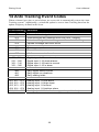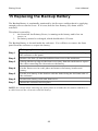
1
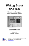
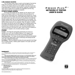
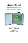
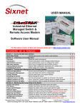
DiaLog Scout-RT SPLC Remote monitoring and alarm notification system User’s Manual Version 10.4 October 19, 2007 Antx, inc. P.O. Box 200816 Austin, TX 78720 877-686-2689 512-255-8306 (fax) www.antx.com INTRODUCTION...................................................................................... 1 1.1 GENERAL OPERATION........................................................................... 1 2 INSTALLATION....................................................................................... 2 2.1 ENABLING POWER ................................................................................. 3 2.2 CONNECTING THE SERIAL CABLE .......................................................... 3 2.3 CONFIGURING THE SERIAL PORT ........................................................... 4 3 FRONT PANEL PROGRAMMING........................................................ 5 3.1 HOW TO READ THE MENUS ................................................................... 5 3.2 HOW TO USE THE KEYPAD .................................................................... 6 3.3 HOW TO ENTER TEXT FOR NAMES ........................................................ 7 3.4 PROGRAMMING SYSTEM SETTINGS ....................................................... 8 3.5 PROGRAMMING PHONE SETTINGS ....................................................... 11 3.6 SMS TEXT AND E-MAIL MESSAGES..................................................... 14 3.7 PROGRAMMING CHANNEL SETTINGS .................................................. 15 4 PROGRAMMING FROM A PC............................................................ 22 5 PROGRAMMING REMOTELY OVER A PHONE............................ 27 5.1.1 Phone numbers........................................................................... 27 5.1.2 Channel settings......................................................................... 28 6 RUN MODE FUNCTIONS ..................................................................... 30 6.1 PHONE STATUS MESSAGES .................................................................. 31 7 GETTING SYSTEM STATUS ............................................................... 31 7.1 FROM THE FRONT PANEL ..................................................................... 32 7.2 REMOTELY.......................................................................................... 34 8 VERIFYING COMMUNICATION ....................................................... 35 9 LISTENING IN FROM A REMOTE CALL ........................................ 36 10 ACKNOWLEDGING ALARMS............................................................ 37 10.1 ACKNOWLEDGE FROM THE KEYPAD .................................................... 37 10.2 ACKNOWLEDGE REMOTELY WHEN CALLED FROM THE SCOUT ............ 38 10.3 ACKNOWLEDGE WHEN YOU CALL THE SCOUT .................................... 39 11 ARMING AND DISARMING ................................................................ 40 11.1 FROM THE FRONT PANEL ..................................................................... 40 11.2 REMOTELY.......................................................................................... 40 12 WRITING DIGITALS AND ANALOGS .............................................. 41 12.1 FROM THE FRONT PANEL ..................................................................... 41 12.2 REMOTELY.......................................................................................... 43 13 RETRIEVING THE EVENT LOG........................................................ 45 13.1 TO VIEW THE EVENT LOG LOCALLY.................................................... 45 13.2 TO RETRIEVE THE EVENT LOG REMOTELY .......................................... 46 14 ANTX TRACKING EVENT CODES.................................................... 48 15 REPLACING THE BACKUP BATTERY ............................................ 49 16 CUSTOMER SERVICE.......................................................................... 50 17 FCC REGISTRATION ........................................................................... 50 1 DiaLog Scout User’s Manual 1 Introduction The Scout-RT SPLC is the most user-friendly and reliable remote monitoring and alarm notification system available. The Scout provides reading and writing of PLC/Modbus registers over a serial link using the Modbus RTU protocol. Mounted in an industrial aluminum enclosure, the Scout provides simple programming either locally through the integral keypad or via a local PC connection. 1.1 General Operation The Scout reads inputs from a PLC or other Modbus device over a serial cable. Any input channel in the Scout can read/write the following registers from a PLC. Function Read coils Read Holding Write Coil Write Holding Modbus Function Code 01 03 05 06 The Scout supports reading from multiple Modbus IDs, as each channel references a unique PLC point specified by: Modbus slave ID Register type Register number The Scout has 2 modes of operation – PROGRAM and RUN. During PROGRAM mode you can change how the Scout operates. During RUN mode the Scout is monitoring and performing alarm notification. The Scout monitors up to 24 inputs continuously. When any one of the inputs changes from the normal-alarm or alarm-normal condition, the Scout immediately informs the Antx Tracking web-based system which records the information and issues any alarm notification methods specified. When any monitored channel goes into and out of the alarm condition, the Scout automatically sends information to the Antx Tracking system via the internal GSM/GPRS modem. NOTE: In this version, the phone-based alarm notification has been made available. 1.1.1 Antx Tracking Alarm Acknowledgment Alarms are acknowledged remotely by pressing the ‘1’ key on your phone keypad when requested by the Antx Tracking system. Antx Tracing informs you that the alarm has been “acknowledged”. 1 DiaLog Scout User’s Manual 2 Installation You can mount the Scout to a panel or it can be flush mounted to a door. The brackets on the either side of the Scout can be removed and turned around for panel mounting. Figure 1 Panel Mount mounting holes Figure 2 Flush Mount cut-out dimensions 2 DiaLog Scout 2.1 User’s Manual Enabling power Connect the provided DC power supply, or another source of 9 to 12VDC, to the Power connection. Move the On/Off switch to the up or On position. The Scout will start its power up diagnostics. Upon completing the power up diagnostics, the Scout will be in Program Mode. If an Access Code has been programmed, the Scout will start up in Run Mode. 2.2 Connecting the serial cable The Scout has a 9-pin connector located on the far right-hand side. The pin configuration is as follows: 1 2 3 CD RCV data XMT data 5 7 8 GND RTS CTS The cable between the Scout and the PLC/Modbus device will have to assure that the RCV on the Scout connects to the XMT on the PLC and visa versa. Serial Port 3 DiaLog Scout 2.3 User’s Manual Configuring the serial port The serial port is configured for the following from the System Setup (3) function when in the Programming mode. Port 1 – external DB9 connection, 2 – 10-pin header Port 1 - set to GSM Port 2 - set to Modbus Master when running - set to Debug when programming Mode 0 – None, 1 - Debug, 2 – Slave, 3 – Master, 4-GSM Baud Rate 0 - 1200 1 – 2400 2 – 4800 3 - 9600 4 – 14400 5 – 19200 6 - 28800 7 – 38400 8 – 57600 9 - 115200 Parity 0 – None, 1 – Odd, 2 - Even Data Bits 7 or 8 Stop Bits 1 or 2 Max Idle 5 – 4000 character times Response Timeout 20 – 6000 msecs Scan Rate 1 – 60 seconds Block Requests 0 – off, 1 - on 4 DiaLog Scout User’s Manual 3 Front Panel Programming The Scout is programmed from the front panel by pressing the keypad to access the various portions of the system. For the most basic application, you can simply program some channels and put the Scout into the RUN mode. In more complex applications, you can program individual names for each channel being monitored, adjust the amount of time channels must be in the alarm condition before starting the call to Antx Tracking and other specific conditions. When programming, all prompts are displayed. You can enter a value or press the # key to keep the current value and move to the next option. NOTE: When you have finished programming, return the Scout to the RUN mode by pressing the 1 key. If the Scout is not in RUN mode, it will not perform any alarm call operations. If you forget to return the Scout to RUN mode, it will automatically return to RUN mode after 30 minutes. 3.1 How to Read the Menus Mode or section of the system Program Mode [0-9]= Available selections. In this case valid inputs are 0 through 9. Parameter to change or view Between Calls Delay 5-3600 secs = 30 Current value of the parameter. For example, Between Calls Delay is currently set to 30 seconds Valid range of values. Between 5 and 3600 seconds 5 DiaLog Scout 3.2 User’s Manual How to use the Keypad The Scout keypad is designed to make programming easy. At the bottom of the front panel is a legend to assist in programming the most common functions. The keypad components are: BLUE – function of key in PROGRAM mode RED – function of key in RUN mode Move to previous selection Move to next selection Text entry of letters and numbers Press at any time to go to the top of the PROGRAM menu Enter this selection The specific functions of each key are: Key 1 3 4 9 0 ** ENTER PREV NEXT HOME Function in PROGRAM mode Toggles the unit between PROGRAM and RUN mode. Enter SYSTEM wide parameters Enter PHONE numbers and parameters Enter CHANNEL parameters View STATUS of each channel To toggle between Positive (+) and Negative (-) when entering zero, full scale and limit values. Enter or keep the current setting Exit the View STATUS screen Go to the PREVious selection Go to the NEXT selection Go to the top of the PROGRAM mode menu 6 DiaLog Scout 3.3 User’s Manual How to Enter Text for Names The DiaLog Scout allows the user to enter names for the Site (Unit) and for each channel. Entering names is very similar to entering names on most cell-phones that are used today. On the bottom of each key, there are letters and numbers. To select a specific letter or number, press that key the designated number of times. For example, to enter the letter ‘L’, press the 5 key 3 times. Key to Press 1 2 3 4 5 6 7 8 9 0 * 1 space A D G J M P T W Q Erases previous letter Number of times to press the key 2 3 4 1 B C 2 E F 3 H I 4 K L 5 N O 6 R S 7 U V 8 X Y 9 Z 0 0 7 5 + . , * # / _ @ DiaLog Scout 3.4 User’s Manual Programming System Settings System settings are generally programmed once during the initial setup of the Scout. Options in this section are: • • • • • • • Site Message Access Code Date and Time Communication Ports Numeric ID Rings to Answer Reset to System Defaults What you do: What the display shows: Step 1 Press the 1 key to enter PROGRAM mode. You can now enter options 0 – 9. Step 2 Press 3 Enter Access Code if requested. Step 3 The pre-recorded Site Message is spoken through the speaker. Press 0 to listen to the current message, 1 to record a new message, or # to move to the next step. If you press 1, this message is displayed. NOTE: If an Access Code has been programmed, the Scout will show a screen to enter it. Site ID Msg 0-play 1-rec = Press # to record Speak your message into the microphone and press the # key when finished. NOTE: The speaker is intended only to confirm that your message was recorded as desired. The voice quality over the phone is excellent even though the voice quality over the speaker may be noisy. Step 4 Program Mode [0-9]= A 20 character name that is displayed on the screen. To enter the name, press the key that corresponds to the letter or number that you want. 8 Recording . . . Press # to stop Site Name nnnnnnnnnnnnnnnnn DiaLog Scout User’s Manual What you do: What the display shows: Step 5 The Numeric ID that will display on a pager is shown. Press # to keep the current value or enter a new value then press the # key. Step 6 The Access Code is displayed. Press # if OK or enter a new 4-digit Access Code. Step 7 The Speaker Volume can be adjusted to be louder (up) or softer (down). Press # when you have the level you desire. NOTE: 7 is maximum volume level Speaker Volume 0-7 = 3 Step 8 Local Speaker specifies whether the speaker is on or off during alarm calls. If off, then the alarm call is not spoken over the local speaker. If On+Monitor, the alarm call and any sound coming in over the phone line are spoken over the local speaker. Speaker Mode 0-2 = On+Monitor Numeric ID nnnnnnnnnnnnnnnnnn Access Code nnnn 0 – Off, 1 – On, 2 – On+Monitor Step 9 Rings to Answer is the number of rings before the Scout answers. Press # if OK or enter a new value as nn (e.g. 03 for 3) Rings to Answer 1-20 = nn Step 10 Scan Rate is the rate at which the Scout reads all registers from the PLC. Press # if OK or enter a new value as nn (e.g. 03 for 3) I/O Scan Rate 1-60 secs = 1 Step 11 Block I/O Mode enabled allows the Scout to optimize communication with the PLC by requesting data in blocks of registers. If the registers being read are nearly consecutive, then this should be on (1). If they are not, set this to off (0). Press # if OK or enter a new value. Block I/O Mode 0-1 = 0 off 9 DiaLog Scout Step 12 User’s Manual What you do: Communication port setup. 1 for Comm1 - DB9, RS-232 port (external) 2 for Comm2 – 10-pin header, RS232 What the display shows: Comm Setup 1-2 = 1 If not changing Comm port settings, skip to Step 20 Step 13 Mode 0 – none (port not used) 1 – debug (programming) 2 – Modbus RTU Master 3 – GSM (cellular phone connection) 4 – EP250 (LOFA) 5 – Modbus Slave Step 14 Set the baud rate for the serial port. 0 = 1200 to 9 = 115200. CommX Baud Rate 0-9 = 7 (38400) Step 15 Set the parity 0 – none, 1 – odd, 2 – even CommX Parity 0-2 = 0 (none) Step 16 Set the data bits 7 or 8 CommX Data Bits 7-8 = 8 Step 17 Set the stop bits 1 or 2 CommX Stop Bits 1-2 = 1 Step 18 The number of characters the SCOUT waits between characters being received. CommX Max Idle 5-4000 chars = 100 Step 19 Response Timeout is the maximum time the SCOUT waits for a response from the PLC after a request is sent. CommX Resp Timeout 20-6000 = 2000 10 CommX Mode 0-5 = 0 (none) DiaLog Scout User’s Manual What you do: What the display shows: Step 20 Set the time and date as needed. Press the # key if the value is correct already. NOTE: The Scout uses a 24-hour clock. Step 21 Reset Config back to the factory default values. Press 0 or # to keep your programming or 1 to reset back to the factory defaults. Step 22 Reset Events back to the factory default values. Press 0 or # to keep your programming or 1 to reset back to the factory defaults. 3.5 Set Date/Time 1-Set = Reset Config 1-rst = Reset Events 1-rst = Programming Phone Settings NOTE: If you are doing all your alarm notification through the Antx Tracking system, you do not need to configure any phone settings. This section is only for calls you want to make using the voice-based alarm notification capability within the Scout. Phone settings consist of options to set for all calls in or out of the Scout. They are generally setup once during initial installation. Phone Settings include: • • Message repeat Phone numbers Between call delay Call Progress delay What you do: What the display shows: Step 1 Press the 1 key for PROGRAM mode. You can now enter options 0 – 9. Step 2 Press 4 Enter Access Code if requested. 11 Program Mode 0-9 = NOTE: If the Scout is in RUN mode and an Access Code has been programmed, the Scout will show a screen DiaLog Scout User’s Manual What you do: What the display shows: to enter it. Step 3 Msg Repeat is the number of times the alarm message will be repeated when an alarm call is made. Press # to keep the current value or enter a new value using 2 digits. (e.g. 03 for 3). Step 4 There are 8 phone numbers that can be entered in the Scout. These are processed in order from 1 to 8. Enter the position of the phone number you want to check or modify. Press # for no changes. Step 5 Enter a call type 1 2 3 Step 6 Voice/Pager SMS Text Email For phone and SMS messages: Msg Repeat 0-20 = nn Enter Phone Pos 1-8 = Pos 1 Call Type 1-3 = 1 Voice/Pager Ph Num: 1234567890 The phone number in the position specified is shown. Press # if OK or enter a new phone number. NOTE: The phone number can be up to 25 numbers long. *2 *7 *8 *9 ** *# For a pager call Deletes phone number Detects a dialtone 2-second delay for a ‘*’ for a ‘#’ (e.g. 5124442233P would call a pager at 5124442233) For e-Mail – enter the e-mail address to receive the message. See Section 3.3 How to Enter Text 12 E:[email protected] DiaLog Scout User’s Manual What you do: for Names for specific details. Step 7 There are 8 phone numbers that can be entered in the Scout. These are processed in order from 1 to 8. Enter the position of the phone number you want to check or modify. Press # for no changes. Step 8 The phone number in the position specified is shown. Press # if OK or enter a new phone number. NOTE: The phone number can be up to 25 numbers long. *2 *7 *8 *9 What the display shows: PosX Call Type 1-3 = Pos 1 Phone Number nnnnnnnnnnnnnnnnn For a pager call Deletes phone number Detects a dialtone 2-second delay (e.g. 5124442233P would call a pager at 5124442233) Step 9 Specifies the amount of time to wait before calling the next number in the list. Pos 1 Next Call Dly 5-3600 secs = nnnn Step 10 If Notify Once is enabled, then upon a successful call, this particular phone number will not be called again. Pos 1 Notify Once 0-1: disabled Step 11 This is the amount of time the Scout waits after issuing the last digit in the phone number before issuing the alarm or numeric pager message. NOTE: 0 means Call Progress is enabled. The Scout will call and wait until the phone has been answered before the alarm message is delivered. If the Scout calls and never delivers the message, then the Scout is not able to determine that the phone has been answered, probably because the voice answering the phone is not loud enough. Loop back to Step 5 13 Pos 1 Call Prog Dly 0-60 secs = nn DiaLog Scout 3.6 User’s Manual SMS text and e-Mail messages SMS text and e-mail messages can be sent if the Scout is equipped with a GSM cell phone and the SMS/e-Mail option has been enabled. SMS text message format: Site ID, channel name, channel name value engineering units Example: Remote Site 343, Tank Level 123.4 ft e-Mail text message format: Site ID channel name channel name value engineering units Example: Remote Site 343 Main Pump Down Tank Level 123.4 ft 14 DiaLog Scout 3.7 User’s Manual Programming Channel Settings This section allows you to configure the information specific to each channel or condition being monitored. For each channel the following options can be programmed. Channel Types System (01) - Power Fail (02) - Low Battery (03) Low Low Battery (05) – Communications channel name channel message channel mode (alarm or status) alarm delay relay (coil) to activate on alarm Digitals (Coil Registers) (11-26) slave address register number channel ID voice message channel name channel mode channel state (Normally Open/Normally Closed) alarm delay redial delay relay (coil) to activate on alarm pulse duration (if mode is set to Status Only) Analogs (Holding Registers) (31-38) slave address register number channel ID voice message channel name register value (signed or unsigned) engineering units decimal position scale input (yes or no) zero and full scale, min and max counts channel mode alarm delay redial delay low limit high limit relay (coil) to activate on low alarm (1-16) relay (coil) to activate on high alarm (1-16) 15 DiaLog Scout User’s Manual What you do: What the display shows: Step 1 Press the 1 key to enter PROGRAM mode. You can now enter options 0 – 9. Step 2 Press 9 Step 3 Enter channel number: 01-05 for system 11-26 for digital 31-38 for analog Program Mode 0-9 = Digital Channels 11-26 = Digital (Read and Write Coils) What you do: What the display shows: Step 1 Enter the Modbus Slave ID of the remote PLC or device that this channel will be read from. 0 = disabled Step 2 Enter the register number to read/write in the PLC or Modbus device. Step 3 The Scout will repeat the current channel message. If the message is OK, press #. To record a new message, press 1 and speak your new 6-second message into the microphone followed by the # key. To listen to the current message again, press 0. NOTE: This message is ONLY delivered if the Scout is configured to make phone calls directly instead of through Antx Tracking. 16 ChanXX Slave ID 0-247 = ChanXX Reg Num 1-9999 = ChanXX ID Msg 0-play 1-rec = DiaLog Scout User’s Manual Digital (Read and Write Coils) What you do: What the display shows: Step 4 Each channel can have a 20 character name that will be displayed whenever the Status is shown or a channel is in alarm. To enter the name, press the key that corresponds to the letter or number that you want. To move to the next character, wait 1 second between entries. Press # key when finished. For example, Character/# How to enter A 2 key – 1 time B 2 key – 2 times C 2 key – 3 times 2 2 key – 4 times S 7 key – 3 times Step 5 The Channel Mode has 3 modes: 0 – disabled (not used0 1 – status only (values are read, but no alarms are generated) 2 – CallOnAlarm – (values are read and alarms are generated) NOTE: for a relay output (write coil), the mode must be set to Status Only Step 6 The Alarm State is 0 for normally open and 1 for normally closed. NOTE: An alarm occurs when the Scout transitions out of these ‘normal’ conditions. Step 7 The Alarm Delay specifies the amount of time the input must be in the alarm condition before a call-out begins. Press # if OK or enter a new 5-digit value as nnnnn (e.g. 00300 for 300) Step 8 The Redial Delay is the amount of time after a channel has been acknowledged before another call is made if the channel is still in the alarm condition. 17 ChanXX Name nnnnnnnnnnnnnnnnn ChanXX Mode 0-2 = 2 CallOnAlarm ChanXX Normal State 0-1 = 0 Open ChanXX Alarm Delay 0-65535 sec = nnnnn ChanXX Redial Dly 1-9999 mins = 60 DiaLog Scout User’s Manual Digital (Read and Write Coils) Step 14 Step 15 What you do: To Activate the Digital (coil) when the channel goes into alarm enter the channel number of a Digital (Coil) channel. NOTE: The relay will follow the channel into and out of alarm. The Pulse Duration specifies the length of time the digital will stay activated. If you specify 0, then the digital will deactivate when all channels that reference it are in the normal condition. What the display shows: ChanXX Alarm Digital Coil 1-16 ChanXX Pulse Dur 0-86400 sec = nnnnn Loop back to Step 1 for Digital channels Analog (Read and Write Holding) What you do: What the display shows: Step 1 Enter the Modbus Slave ID of the remote PLC or device that this channel will be read from. 0 = disabled Step 2 Enter the register number to read/write in the PLC or Modbus device. Step 3 The Scout will repeat the current channel message. If the message is OK, press #. To record a new message, press 1 and speak your new 6-second message into the microphone followed by the # key. To listen to the current message again, press 0. NOTE: This message is ONLY delivered if the Scout is configured to make phone calls directly instead of through Antx Tracking. 18 ChanXX Slave ID 0-247 = ChanXX Reg Num 1-9999 = ChanXX ID Msg 0-play 1-rec = DiaLog Scout User’s Manual Analog (Read and Write Holding) What you do: What the display shows: Step 4 Each channel can have a 20 character name that will be displayed whenever the Status is shown or a channel is in alarm. To enter the name, press the key that corresponds to the letter or number that you want. To move to the next character, wait 1 second between entries. Press # key when finished. For example, Character/# How to enter A 2 key – 1 time B 2 key – 2 times C 2 key – 3 times 2 2 key – 4 times S 7 key – 3 times Step 5 Indicates how the value being read by the Scout is interpreted. 1 – 16-bit signed 0 – 16-bit unsigned Step 6 Specify the engineering units: 0 – none 1 – pct 2 – ppm 3 – gals 4 – gpm 5 – gph 6 – ft 7 – rpm 8 – psi 9 – degC 10 – degF 11 – inches 12 – meters 13 – kmeters 14 – liters 15 – kliters 16 – grams 17 – kg 18 – lbs 19 - volts 20 - ma Step 7 Specify the location of the decimal point by indicating the number of digits to the right of the decimal point. For example, 2 would provide 44.33 19 ChanXX Name nnnnnnnnnnnnnnnnn ChanXX Reg Value 0-1 = 1 signed ChanXX Engr Units 0-20 = 0 (none) ChanXX Dec Pos 0-5 = 1 DiaLog Scout User’s Manual Analog (Read and Write Holding) What you do: Step 8 What the display shows: If the value being read is in engineering units, then set to 0. If the value being read is in counts, then it can be scaled to engineering units in the Scout. Set to 1. ChanXX ScaleInput 0-1 = 0 No Skip to Step 13 if not Scaling Step 9 Specify the zero value in engineering units that corresponds to the minimum value in counts. Step 10 Specify the span value in engineering units that corresponds to the minimum value in counts. For example, to convert a value that ranges from 20.0 to 100.0 deg, the Zero value would be 200 and the Full Scale would be 1000, assuming a Decimal Position of 1. Step 11 Specify the minimum value in counts that will be read from the PLC/Modbus register. ChanXX Min Counts 0-65535 = 0 Step 12 Specify the maximum value in counts that will be read from the PLC/Modbus register. ChanXX Max Counts 0-65535 = 32767 Step 13 The Channel Mode has 3 modes: 0 – disabled (not used0 1 – status only (values are read, but no alarms are generated) 2 – CallOnAlarm – (values are read and alarms are generated) Step 14 The Alarm Delay specifies the amount of time the input must be in the alarm condition before a call-out begins. Press # if OK or enter a new 5-digit value as nnnnn (e.g. 00300 for 300) Step 15 The Redial Delay is the amount of time after a channel has been acknowledged before another call is made if the channel is still in the alarm condition. 20 ChanXX Zero Scale +/-99999 = ±0.0 ChanXX Full Scale +/-99999 = ±100.0 ChanXX Mode 0-2 = 2 CallOnAlarm ChanXX Alarm Delay 0-65535 sec = nnnnn ChanXX Redial Delay 1-9999 mins = 60 DiaLog Scout User’s Manual Analog (Read and Write Holding) Step 16 What you do: If the current reading is below the Low Limit, the channel goes into alarm and initiates a call and/or a relay activation. NOTE: always has 1 digit to the right of the decimal Step 17 If the current reading exceeds the High Limit, the channel goes into alarm and initiates a call and/or a relay activation. Step 18 To Activate the Digital (coil) when the channel goes into alarm enter the channel number of a Digital (Coil) channel. NOTE: The digital will follow the channel into and out of alarm. Step 19 To Activate the Digital (coil) when the channel goes into alarm enter the channel number of a Digital (Coil) channel. NOTE: The digital will follow the channel into and out of alarm. Loop back to Step 1 (Analog channels) 21 What the display shows: ChanXX Low Limit 0-99999 = xxxxx ChanXX High Limit 0-99999 = xxxxx ChanXX Lo Alm Digital Coil 1-16 ChanXX Hi Alm Digital Coil 1-16 DiaLog Scout User’s Manual 4 Programming from a PC The Scout can be programmed from a PC by using either port on the Scout. Use whichever port is more convenient for your needs. Port 1 is connected to the GSM modem and Port 2 is connected to the PC. Set the port that you are using to Debug mode (via Programmimg > System) NOTE: When the Scout is being programmed from a PC, the Scout is not scanning the PLC. On your PC, you can use Hyperterminal or any other terminal emulation package. Connect the Scout to the PC and start your terminal emulation program, making sure to adjust your communications settings to match those on port 2 of the Scout. The Scout displays the following menu after the “Enter” key is pressed on your PC. Dialog Scout – Scout-RT SPLC (v3.3) 0) 1) 2) 3) 4) 5) 6) 7) View System Cfg View Chan Cfg Timers Data Events Report Site Setup System Maint (view system configuration programming) (view channel programming) (view running timers) (view current data for each channel) (view the event log) (view a status report of all channels) (program the Scout) (system maintenance items) Cmd => 22 DiaLog Scout User’s Manual To program the Scout, use Option 6 – Site Setup. menu is displayed: The following Cmd => 6 ******** 1) 2) 3) 4) 5) 6) Site Setup ******** System Channels PSTN GSM Ports Prog GSM ...> 2 Dialog Scout – Scout-RT SPLC (v9.6) *** Channel Configuration *** Chan Num [1-16]: 12 Device ID [-1-247]: 240 Register Number [1-9999]: 101 Chan Name: Pump 1 Failure Mode [0-2]: 2 (CallOnAlarm) Normal [0-1]: 0 (Open) Alarm Delay (secs) [0-65535]: 3 Redial After ACK Delay (secs) [0-86400]: 3600 Alarm Relay [1-16]: -1 (disabled) Enter new values or press Enter to leave as is. *** Channel Configuration *** Chan Num [1-8]: 31 Device ID [-1-247]: 240 Register Number [1-9999]: 221 Chan Name: Ana 1 Mode [0-2]: 2 (CallOnAlarm) Alarm Delay (secs) [0-65535]: 3 Redial After ACK Delay (secs) [0-86400]: 3600 Decimal Position [0-5]: 1 Engineering Units [0-18]: 6 (ft) Signed Register [0-1]: 1 Scale Value [0-1]: 1 Zero Scale [-99999-99999]: 0 (+0.0) Full Scale [-99999-99999]: 1000 (+100.0) Zero Scale Counts [-65535-65535]: 0 Full Scale Counts [-65535-65535]: 32767 Low Alarm Limit [-99999-99999]: 200 (+20.0) High Alarm Limit [-99999-99999]: 500 (+50.0) Low Alm Relay [1-16]: -1 High Alm Relay [1-16]: -1 23 Enter new values or press Enter to leave as is. DiaLog Scout User’s Manual The following is an example of the View Configuration Cmd => 0 System Configuration ----------------------------------------------------Model Cfg Ver Cfg Size Cfg Timestamp : : : : Scout-RT SPLC 0200 2808 06/28/06 08:45:00 ID Msg Recorded Alpha ID Numeric ID Access Code Message Repeat Volume Speaker Mode Block Requests Scan Rate (secs) Auto Updates Interval Start Time : : : : : : : : : : : : No My Scout RT 5122552800 -001 2 3 On+Monitor 1 1 enabled 01:00:00 00:00:00 Country Ring Count Validate Ring DTMF Gain DTMF On/Off : : : : : US 2 disabled 0 80 msecs Busy: Min Max Min Max : : : : 350 650 350 650 : : : : 1700 2300 3700 4300 On On Off Off Ringback 1: Min On Max On Min Off Max Off msecs msecs msecs msecs msecs msecs msecs msecs Port: 1 2 -------------------------------------------------------Mode Master Debug Slave ID 126 126 Baud 9600 9600 Parity None None Data Bits 8 8 Stop Bits 1 1 Max Idle (chars) 100 20 Resp Timeout (msecs) 2000 2000 24 DiaLog Scout User’s Manual Continued from previous page… GSM Config ----------------------------------------------------GSM Model MODEM ID Attach String SMS Option Auto ACK Svc Provider ID Name Gateway Number APN User Name Password Forwarding Char Src/Dst Port IP Address GPS Mode Time Zone Latitude Longitude : : : : : : : : : : : : : : : : : : SAG 1203 AXSL40009 *99# 1 1 2 Cingular +121 isp.cingular [email protected] CINGULAR1 0a 2290 066.219.045.101 Fixed Central N30 30 15.300 W097 41 34.000 Phone List ----------------------------------------------------Position 1 Phone Number Call Progress Delay Next Call Delay . . . Position 8 Phone Number Call Progress Delay Next Call Delay : 2558235 : 0 secs : 30 secs : : 0 secs : 30 secs 25 DiaLog Scout User’s Manual The following are from the View Channel menu option: ******** Channels ******** 1) Chan Configs 2) Register Summary 3) Slave Device List Channel Config ----------------------------------------------------Chan Type [1-Sys, 2-Dig, 3-Ana]: Dig Chan Num [1-16]: Chan 6: Dig 1 Slave ID : Reg Number : Msg Recorded : Alm Mode : Normal : Alm Delay : Redial Delay : Relay Chan : Pulse Dur : 1 2 101 No CallOnAlarm Open 3 secs 3600 secs -1 0 secs Chan Num [1-8]: 1 Chan 22: Ana 1 Slave ID : 240 Reg Number : 221 Msg Recorded : No Alm Mode : CallOnAlarm Alm Delay : 3 secs Redial Delay : 3600 secs Dec Pos : 1 Engr Units : 0 (none) Reg Value : signed Scale Input : yes Zero Scale : +0.0 Full Scale : +100.0 Min Counts : 0 Max Counts : 32767 Low Limit : ... High Limit : ... Low Relay : -1 High Relay : -1 Register Summary ----------------------------------------------------D01: D05: D11: A01: A08: Dig Dig Dig Ana Ana 1 5 11 1 8 ID=2 ID=25 ID=247 ID=240 ID=121 Reg=101 Reg=201 Reg=1 Reg=221 Reg=3001 26 DiaLog Scout User’s Manual 5 Programming remotely over a phone NOTE: This capability is ONLY available if the GSM SIM card supports voice calling. If the Scout is only being used to alarm via Antx Tracking, then this capability is not available. When you call-in, the Scout will: • Repeat the current status • 3 “beeps” You have 5 seconds after the 3 ‘beeps’ to press the # key on your phone to inform the Scout that you want to perform remote programming. After pressing the # key, the Scout will say “System ready, enter selection.” 5.1.1 Step 1 Phone numbers What you do: What the Scout says: Press # within 5 seconds after hearing 3 “beeps” “System ready. Enter selection.” Press 4 or press # if finished. “Phone setup. Enter phone position. Or press # to exit” NOTE: If an Access Code has been programmed, the Scout says“Enter Access Code” Step 2 Enter Call type. Press # when finished. “The Call Type is” [1-4] Step 3 Enter a new phone number followed by the # key or press the # key to keep the current phone number. “Position” nn “Phone number is” nnnnnnnnnnnn Step 4 Press # if the number is OK or enter a new number followed by the # key. “Position” nn “Phone number is” nnnnnnnnnnnn “Enter new number or press # to exit” Loop back to Step 2 27 DiaLog Scout 5.1.2 User’s Manual Channel settings What you do: What the Scout says: “System ready. Enter selection.” Step 1 Step 2 Press 9 or press # if finished. NOTE: If an Access Code is been programmed, the Scout says “Enter Access Code” Enter Access Code if requested. “Channel setup.” Enter a channel number “Enter channel number or press # to exit” For Digital (Coils) … Step 3 If you enter a 1 to record a new message, listen to the instructions. “The channel message is <message>. Press 1 to record a new message or press # to exit.” Step 4 Enter your selection “The channel normal state is” open/closed. “Enter new normal state or # to exit” # 0 1 Keep current Normally open Normally closed NOTE: A new entry is repeated back. Step 5 Enter your selection # 0 1 Keep current Status only Call on alarm “The channel mode is” “status only” or “call on alarm” “Enter new selection or press # to exit” NOTE: A new entry is repeated back. Loop back to Step 2 For Analog … Step 6 If you enter a 1 to record a new message, listen to the instructions. 28 “The channel message is <message>. Press 1 to record a new message or press # to exit.” DiaLog Scout Step 7 User’s Manual What you do: Enter your selection # 0 1 Keep current Status only Call on alarm What the Scout says: “The channel mode is” “status only” or “call on alarm” “Enter new selection or press # to exit” NOTE: A new entry is repeated back. Step 8 Enter a new low limit with 1 assumed digit to the right of the decimal, or # if the current value is OK. Enter *7 to disable the low limit. e.g. 252 would be 25.2 % “The channel low limit is nn.n %” “Enter new selection or press # to exit” NOTE: A new entry is repeated back. Step 9 Enter a new high limit with 1 assumed digit to the right of the decimal. Enter *7 to disable the high limit. e.g. 850 would be 85.0 % “The channel high limit is nn.n %” “Enter new selection or press # to exit” NOTE: A new entry is repeated back. Loop back to Step 2 For Write Coils… Step 10 If you enter a 1 to record a new message, listen to the instructions. “The channel message is <message>. Press 1 to record a new message or press # to exit.” Step11 Enter your selection “The channel pulse duration is” nnnn “Enter new selection or press # to exit” NOTE: A new entry is repeated back. Loop back to Step 2 29 DiaLog Scout User’s Manual 6 RUN Mode functions While the Scout is in RUN mode it is scanning all inputs, evaluating them for transitions into and out of alarm conditions, performing alarm calls and updating the display. The default RUN mode display looks like this: Run Mode 03:02:02 Alms or Acked Phone Status (offhk, ring, delay, pherr) Armed or Disarm There are 7 functions that can be performed while in RUN mode. Function Capability Keypad 0 Keypad 1 Keypad 2 Keypad 5 Keypad 7 Keypad 9 Phone Check Get system status Enter Program mode Toggle Arm/Disarm View Event Log Activate Relay Acknowledge alarms Test phone line 30 DiaLog Scout 6.1 User’s Manual Phone Status messages The following messages can be displayed in the Phone Status field. Message Meaning delay Scout is waiting the between call delay to make another call erSMS General SMS error lkout Lockout – GSM cell phone is turned off for 1 hour while charging the battery noCAR Lost carrier while transmitting SMS or e-mail noGSM Cannot communicate with the GSM cell phone (serial cable connected? SIM card installed correctly?) noGW SMS/e-mail Gateway number is invalid noReg No registration on GSM phone (SIM card installed correctly? Out of minutes?) noNUM SMS phone number invalid noRSP No response from the SMS service center noSC No SMS service center detected offhk Phone is offhook for a phone call or phone check. pherr Phone error – no current detected from phone line. (unplugged?) phflt Phone fault – no dialtone detected (dead line?) ring Ring is detected on call out or call in. WrErr Write error to the Serial EEPROM on the Scout board. (contact Antx for support/repair) 7 Getting System Status System Status reports the current conditions of the Scout. It will report any channels that are in alarm or acknowledged, including the primary power, battery and communications channels. 31 DiaLog Scout 7.1 User’s Manual From the front panel The Scout displays the first channel (Power). To view the other channels press the PREV key to move backward or the NEXT key to move forward through all the channels. The channels are: Power, Low Battery, Low Low Battery, Phone line status, each input channel and then the version of the firmware in the Scout. 31 – Channel Name Val = 45 DegF Press 0 Cycle through all channels PREV or NEXT 31 – Channel Name <alarm state> 11 – P1 Run Time 0 - Norm Press 0 11 – P1 Run Time Starts = xxxx Press 0 Press 0 31 – Channel Name Low Limit = xxxxxx 11 – P1 Run Time Starts Limit = 30 Press 0 Press 0 31 – Channel Name High Limit = xxxxxx 11 – P1 Run Time Run = days HH:MM:SS Press 0 Press 0 31 – Channel Name Max = xxxxxx 11 – P1 Run Time Run Limit = xxxxxx secs Press 0 Press 0 31 – Channel Name Min = xxxxxx Press 0 Analog Channels Digital Channels with Reports turned on 32 DiaLog Scout User’s Manual What you do: What the display shows: Step 1 Press the 0 key. Step 2 Primary power is being supplied. Press the NEXT key. Power normal Battery level is normal. Press the NEXT key. Low Batt normal Through all channels… Digital 01 is in the alarm condition and is closed. Press the NEXT key. D01 <chan name> 1 alarm NOTE: If the channel being viewed is an analog input or a digital input that has Reports enabled, there is additional information that can be seen by pressing the ‘0’ key repeatedly. The additional information is: Analog input Alarm state Low limit High limit Min since midnight Max since midnight Loop through remaining channels DiaLog Scout version Scout-RT SPLC V3.3 Loop back to Step 1 NOTE: Press the # on the keypad to stop the System Status display. 33 DiaLog Scout 7.2 User’s Manual Remotely The System Status can be retrieved remotely by calling into the Scout from a phone. The Scout will answer after the number of rings specified by Rings to Answer. Then the Scout will: What you do: What the Scout says: Step 1 Dial the DiaLog Scout phone number Site ID Message (followed by any channels in alarm) beep beep beep Step 2 Press the # key. (within 5 seconds) “System ready. Enter selection.” Step 3 Press 0 “System status.” The System Status report is spoken. “Enter channel number or press # to exit” Step 4 Enter a channel number Channel message “is normal/in alarm’ “The present value is open/closed” or “The present value is xx.x ” Loop back to Step 3 or enter # to exit 34 DiaLog Scout User’s Manual 8 Verifying Communication When a channel is configured to read from a PLC or Modbus device, the Scout reads all channels every ½ second. If the Scout is not able to communicate correctly, the state of the Communication channel (05) will show an alarm. NOTE: If communication with a Modbus device is lost, the Communication channel will not go into alarm until the Alarm Delay period, which is defaulted to 10 seconds. To verify that the Scout is reading values correctly, look at the Status (0) of the Communication channel (05). Serial communication channel indicates that all communications is operating properly. Serial communication channel indicates that the communications with Modbus Slave ID 122 is not working. Potential causes are: 1. 2. 3. 4. 5. 6. Comm norm Comm id: 122 in alm The serial cable is disconnected. The ID is not correct. The Baud Bate is not correct. The Register Type or Register Number are not correct. The Max Idle it too low The Response Timeout is too low If some channels are being read and others are not, check the Status for each channel to determine which are having problems. Input channel indicates that the channel is in alarm and there is a loss of communication. Chan xx <status> The <status> field switches between the alarm condition and a communication failure. For example, In alm and Comm 35 0.00 ppm DiaLog Scout User’s Manual 9 Listening In from a remote call NOTE: This capability is ONLY available if the GSM SIM card supports voice calling. If the Scout is only being used to alarm via Antx Tracking, then this capability is not available. The DiaLog Scout allows you to call into it from a phone and Listen-In on the noise around the Scout. This is typically used to determine if motors, pumps, fans, etc. are running. What you do: What the Scout says: Step 1 Dial the DiaLog Scout phone number Site ID Message (followed by any channels in alarm) beep beep beep Step 2 Press the # key (within 5 seconds) “System ready. Enter selection.” Step 3 Press the 5 key to enable Listen-In The Scout’s microphone is turned on for 60 seconds. Press the # key during the 60 seconds. Disables Listen-In “System ready. Enter selection.” 36 DiaLog Scout User’s Manual 10 Acknowledging alarms NOTE: This capability is ONLY available if the GSM SIM card supports voice calling. If the Scout is only being used to alarm via Antx Tracking, then this capability is not available. A channel goes into alarm when it transitions out of the normal condition specified in the Alarm State. For example, if a channel has an Alarm State of Normally Open, then the channel goes into alarm when the input closes. The channel will stay in alarm as long as the input is closed. If the Alarm Type is set to Latching, then it will stay in alarm, even if the input goes back to open, until the channel is acknowledged. When any channel goes into alarm and the Channel Mode is set to Call on Alarm, the Scout will start calling the phone numbers in the Phone List. It will continue to call through the list of phone numbers until the channel goes out of alarm or until it is acknowledged. When acknowledged, the Scout will stop calling and wait the time specified by the Ack Redial Delay before starting to call again if the channel is still in the alarm condition. 10.1 Acknowledge from the keypad While in RUN mode, press the ACK key. The Scout will change the display information for the channel(s) in alarm from Alarm to Acknowledged and stop calling. 37 DiaLog Scout User’s Manual 10.2 Acknowledge remotely when called from the Scout NOTE: This capability is ONLY available if the GSM SIM card supports voice calling. If the Scout is only being used to alarm via Antx Tracking, then this capability is not available. The Scout calls the phone numbers programmed into the Phone List beginning with the first position. If the call is busy, the Scout will go to the next number. What you do: What the Scout does: Step 1 Calls next phone number. Step 2 Waits time specified by the Call Progress Delay for that phone number. Step 3 Says: Site Message ID Channel Message ID “is in alarm” “please acknowledge” You have 5 seconds to press the 9 key to acknowledge the alarm. If you do not acknowledge, loop back to Step 3 the number of times specified by Msg Repeat If you do acknowledge “Channel acknowledged.” beep beep beep NOTE: After all the channels have been spoken, the Scout will give you three (3) beeps. You have 5 seconds to press the # key if you wish to continue. If you do not press the # key. “Good-bye” 38 DiaLog Scout User’s Manual 10.3 Acknowledge when you call the Scout NOTE: This capability is ONLY available if the GSM SIM card supports voice calling. If the Scout is only being used to alarm via Antx Tracking, then this capability is not available. If you receive a pager notification that a channel is in alarm and you call into the Scout, the Scout asks you to acknowledge any alarms. Step 1 What you do: What the Scout does: Call into the Scout Says: Site Message ID Channel Message ID “is in alarm” “Please acknowledge” You have 5 seconds to press the 9 key to acknowledge the alarm. If you do acknowledge “Channel acknowledged.” beep beep beep NOTE: After all the channels have been spoken, the Scout will give you three (3) beeps. You have 5 seconds to press the # key if you wish to continue. If you do not press the # key. “Good-bye” 39 DiaLog Scout User’s Manual 11 Arming and Disarming At times it may be beneficial to Disarm the Scout to prevent it from calling out. This is generally done when you are performing maintenance on equipment being monitored and do not want unnecessary alarms generated. NOTE: When the Scout is disarmed, all scanning of I/O stops. You can manually write to coils and holding registers either locally or remotely. 11.1 From the front panel NOTE: The Scout must be in the RUN mode What you do: Step 1 What the display shows: Press the 2 key to toggle between Armed and Disarmed. Run Mode armed 03:04:07 NOTE: If the Scout is Disarmed, it automatically re-Arms after 30 minutes. 11.2 Remotely NOTE: This capability is ONLY available if the GSM SIM card supports voice calling. If the Scout is only alarming via Antx Tracking ,this capability is unavailable. You can Arm or Disarm the Scout when you call into it. What you do: What the Scout says: Step 1 Dial the DiaLog Scout phone number Site ID Message (then any channels in alarm) beep beep beep Step 2 Press the # key within 5 seconds “System ready. Enter selection.” If an Access Code has been activated, you will be requested to enter it. Step 3 Press 2 to toggle between arm/disarm. “System is armed/disarmed” “Return to arm in 30 minutes” “System ready. Enter selection.” Loop back to Step 2 40 DiaLog Scout User’s Manual 12 Writing Digitals and Analogs Digital (Coils) and Analog (Holding Registers) can be written to manually either locally from the keypad or remotely over a phone. Both of these functions are activated by pressing the 7 key. If the coil is also controlled via a digital or analog channel going into alarm, the coil will perform the programmed function in addition to any manual operations. 12.1 From the front panel NOTE: The Scout must be in the RUN mode What you do: Step 1 What the display shows: Press the 7 key to see the Set Outputs selection screen. Enter the channel number for the Digital (Coil) or Analog (Holding) Register. Set Outputs 1-Dig 2-Ana = If the Channel number is an Analog, go to Step 4. Step 2 Select the Digital channel to control. Step 3 The channel is a Digital. Enter 0 to deactivate the digital (coil) or 1 to activate. NOTE: Once the command has been accepted, the value to the far right of will be the actual read back value of the digital. Therefore, if the command entered was a ‘1’ to activate and the display shows ‘ 0’, the digital was not set and there may be a communication problem. Loop back to Step 1 41 Set Digital 1-16 = <channel name> 0-off 1-on = 0 DiaLog Scout User’s Manual Step 4 Select the Analog channel to control. Step 5 The channel is an Analog. The value xx.xx represents the last value read back from this analog. For example (assume 2 decimal places): You enter: Set = 5629# If the write was successful, 56.29 will be displayed as the value read back from this analog. You may now enter a new value for this analog. The value is entered as 1 to 5 consecutive numbers. If the pound key is pressed and no numbers have been entered, the system returns to prompt for an output channel number. When the # key is pressed, the number is rewritten showing the decimal point location. If this value is correct, press the pound key to write the new value to the holding register. If the value is not correct, hit any key except the pound key to abort this entry and reenter a new value. Loop back to Step 1 42 Set Analog 1-8 = <channel name> Val = ±xx.x DiaLog Scout User’s Manual 12.2 Remotely NOTE: This capability is ONLY available if the GSM SIM card supports voice calling. If the Scout is alarming via Antx Tracking, then this capability is not available. You can activate or deactivate the relay when you call into the Scout or when the Scout has called you during an alarm notification. What you do: What the Scout says: Step 1 Dial the DiaLog Scout phone number Site ID Message (followed by any channels in alarm) beep beep beep Step 2 Press the # key within 5 seconds “System ready. Enter selection.” If an Access Code has been activated, you will be requested to enter it. Step 3 Press 7 to listen to the Output Channels prompt. “Output Channels. ” “Enter channel number or press # to exit.” If the Channel number is a Holding Register, go to Step 6. Step 4 Enter channel number. For a write coil channel Recorded channel message or “Relay output channel nn” “Relay is energized/deenergized” “Enter new selection” Step 5 Press 1 to activate the relay or 0 to deactivate the relay. The new state of the coil is the read back to you. Press the pound key to return to the channel prompt. “Relay is energized (or deenergized)” “Enter new selection or press # to exit.” Loop back to Step 1 Step 6 Enter channel number. For a write holding channel “Analog output channel nn” “The present value is xx.xx” “Enter new value or press # to exit” 43 DiaLog Scout User’s Manual Step 7 Enter a new value. For example, 5678# “The new value is 56.78” “Press # to enter “Enter new value or press # to exit.” Step 8 If this value is correct, press the pound key to write the value to the holding register. NOTE: If the value is not correct, hit any other key to abort this entry and reenter a new value. If the entry is aborted the system says “No Entry”. “The present value is 56.78” “Press # to enter “Enter new value or press # to exit.” Loop back to Step 1 44 DiaLog Scout User’s Manual 13 Retrieving the Event Log The DiaLog Scout keeps the last 100 events that occurred in a local non-volatile log. The Event Log can be viewed locally on the display or retrieved remotely over the phone. The PREV moves backwards and the NEXT moves forwards through the logs. 13.1 To view the Event Log locally What you do: What the display shows: Step 1 Press the 1 key to enter Program Mode Step 2 Press the LOG (5) key Step 2 Press 0 to view the Event Log Press 1 to view the Data Log Step 3 Press the NEXT key to advance forward through the Event Log or the PREV key to move backward. Program Mode 0-9 = View Log 0-Evt 1-Data = 1) PROG Mode date time Press the # key when you are finished. Press # when finished 45 2) DIN3 Cl Alm date time DiaLog Scout 13.2 User’s Manual To retrieve the Event Log remotely NOTE: This capability is ONLY available if the GSM SIM card supports voice calling. If the Scout is only being used to alarm via Antx Tracking, then this capability is not available. The Event Log can be retrieved remotely via a phone call in to the DiaLog Scout. What you do: What the Scout says: Step 1 Dial the DiaLog Scout phone number Site ID Message (followed by any channels in alarm) beep beep beep Step 2 Press the # key (within 5 seconds) “Enter selection.” Step 3 Press the 6 key. “Event log start” “Type is ##’ “Date is xx xx” “Time is xx xx xx” Step 4 Press the 1 key to move to the next event, press the 0 key to move to the previous event. NOTE: if the Date or Time is the same as the previous event, then the Date or TIme will not be repeated. NOTE: the Scout will say “Event log end” prior to the type of the last entry in the event log. Loop back to Step 4 or press # to exit. 46 “Type is ##’ “Date is xx xx” “Time is xx xx xx” DiaLog Scout Event # User’s Manual Event Description Event # Event Description 0 NULL Event 42 GSM unsolicited reg event 1 Power On 43 GSM result of +CFUN cmd 2 Dead Task with task number 44 GSM attach to network 3 System Armed 45 GSM has reset 4 Armed 46 Pager call 5 6 RUN Mode PROGram Mode 47 48 Phone check Telco/GSM Sending SMS msg 7 Configuration Change 49 Sending e-mail msg 8 Reset to System Defaults 50 Sending GPRS UDP/PAD msg Receiving SMS msg with cmd 9 Call Answered 51 10 No Dial Tone 52 Railed to execute SMS cmd 11 12 Call Busy Call Error 53 54 Automatic update call out Reset DIN run limit 13 Call Aborted 55 Reset DIN starts 14 Call Timeout 56 Reset AIN totals 15 Call No Answer 57 Write Holding 16 Call Incoming 58 Receive DTMF tone 17 18 Call Complete Voice Call 59 60 Comm OK Comm Fail 19 Data Call 61 Set notify 20 Alarms acknowledged locally 62 Clear notify 21 Alarms acknowledged remotely 63 Normal GPRS call 22 Alarm call / phone position 64 Between calls timer state 23 24 Open alarm / digital channel number Closed alarm / digital channel number 65 66 Time has been set GPS fix (1-valid,0-invalid) 25 Run time alarm / digital channel number 67 Midnight data posting to AT 26 Starts alarm / digital channel number 68 GSM modem lockout start 27 Low alarm / analog channel number 69 GSM modem lockout active 28 High alarm / analog channel number 70 GSM modem lockout end 29 30 Totalization alarm / analog channel number Channel is normal / channel number 31 Channel acknowledged / channel number 32 Relay channel on / channel number 33 Relay channel off / channel number 34 Normal data value for channel 35 36 Starts data for digital channel Run time data for digital channel 37 Totalizer data for analog channel 38 Maximum value for analog channel 39 Minimum value for analog channel 40 Send status report 41 42 Send events report Unknown 47 DiaLog Scout User’s Manual 14 Antx Tracking Event Codes When a channel goes into or out of alarm, an event code is automatically sent to the Antx Tracking system. Additionally, a scheduled update is sent to Antx Tracking based on the update frequency defined in the Scout. Event Number Definition 471 472 473 474 Alarms Acknowledged Acknowledged last message sent from Antx Tracking Not acknowledged last message sent from Antx Tracking Update message sent from Scout 101 104 105 Primary power alarm Power normal Modbus communication alarm 201 - 216 251 – 266 301 – 316 351 – 366 480 481 482 601, 611…671 602, 612…672 603, 613…673 604, 614…674 605, 615…675 Digital input 1-16 rum time alarms Digital input 1-16 starts alarms Digital input 1-16 back to normal Digital input 1-16 in alarm Daily digital starts counter Daily digital run durations Daily analog totals Analog input 1-8 low alarm Analog input 1-8 high alarm Analog input 1-8 normal Analog input 1-8 totalizer alarm Analog input 1-8 failsafe alarm (open-loop detection) 48 DiaLog Scout User’s Manual 15 Replacing the Backup Battery The Backup Battery is continually monitored by the Scout to confirm that it is supplying enough power to run the Scout. If it is not, then the Low Battery (02) alarm will be activated. This alarm is caused by: 1. the Scout has lost Primary Power, is running on the battery and is low on power, or 2. the battery cannot be recharged, which should take 6-12 hours. The Backup Battery is located inside the enclosure. You will have to remove the front panel from the enclosure to expose the battery. Step 1 Battery replacement procedure If panel mounted, dismount the enclosure by loosening the screws holding the enclosure to the panel. Step 2 Remove the four (4) nuts that hold the front cover to the enclosure. Step 3 Slowly tilt the top edge of the front cover away from the enclosure to expose the cable connecting the electronics to the battery. Step 4 Put the front cover in a safe place and remove the battery bracket and battery. Step 5 Put the new battery in the bracket with the leads facing the left-hand side of the enclosure. Step 6 Reattach the battery cable and front cover. Step 7 Mount the enclosure back in place. NOTE: be careful when removing the front panel as it holds the electronics and there is a cable between the electronics and the battery. 49 DiaLog Scout User’s Manual 16 Customer Service Antx customer service can be reached toll-free at 877-686-2689. Antx, inc. P.O. Box 200816 Austin, TX 78720 www.antx.com [email protected] 17 FCC Registration The Federal Communications Commission (FCC) has established rules that permit this device to be directly connected to the telephone network. Standardized jacks are used for these connections. This equipment should not be used on party lines or coin lines. If this device is malfunctioning, it may also be causing harm to the telephone network. This device should be disconnected until the source of the problem can be determined and until repair has been made. If this is not done, the telephone company may temporarily disconnect service. The telephone company may make changes in its technical operations and procedures. If such changes affect the compatibility or use of this device, the telephone company is required to give adequate notice of the changes. You will be advised of your right to file a complaint with the FCC. If the telephone company requests information on what equipment is connected to their lines, inform them of: a. The telephone number this unit is connected to b. The ringer equivalence number: 0.2B c. The USOC jack required d. The FCC registration number: 60DAL02BSCOUT Items b and d are indicated on the label. The ringer equivalence (REN) is used to determine how many devices can be connected to your telephone line. In most areas, the sum of the REN's of all devices on any one line should not exceed five. If too many devices are attached, they may not ring properly. 50 Antx, inc. P.O. Box 200816 Austin, TX 78720 512/255-2800 512/255-8306 (fax) www.antx.com