1
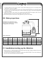
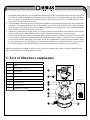
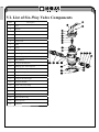
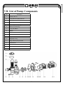
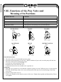
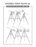
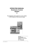
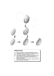
EN
COMPLETE SAND FILTRATION
WITH SIX-WAY VALVE
AND PUMP ON BASE PLATE
(Models: FSP350, FSP450, FSP500, FSP650)
INSTALLATION
AND
USER GUIDE
i
Please read the user manual
EN
Content
I.
II.
III.
IV.
V.
VI.
VII.
VIII.
Function ............................................................3
Installation.........................................................3
Main proportions...............................................4
Installation/starting up the filtration ..................4
List of filtration components .............................5
List of six-way valve components ...................6
List of pump components .................................7
Functions of six-way valve
and meaning of its positions .............................8
Thank you for choosing our product and for trusting our company. Please, read the instructions carefully and
follow the steps indicated in our user guide before the initiation of this product in order to avoid the damage
of the equipment or unwanted injury.
2
EN
I. Function
The filter uses a special filtration sand to capture the dirt components from the pool water. A filter container,
operating as a permanent dirt collector, is filled with the filtration sand. When the regulating valve remains
in the position “FILTER“, the pool water containing the dirt, sucked through the system of hoses, is automatically forced in the regulating valve with patented filter and it is led from this place to the top part of the
filtration container. The water, pushed through the sand, removing the fine dirt, is taking back to the bottom
part of the container. Through the regulating valve, the water comes back to the pool by hoses. The whole
process is continuous and automatic. It ensures the complete re-circulation of the pool water through the
filter and the hose system.
After some time of operation, the dirt accumulated in the filter may cause upsetting of water conduit through
the sand and reduce he flow through the filtration unit. This process indicates to the fact that the filter should
be cleaned. If you set the valve bar in the position BACKWASH, the water flow will automatically return,
so it will flow from the bottom of the container through the filtration sand from which it rinses the sedimentary dirt to the waste pipe. If the filter is rinsed, set the bar in set the bar in the position RINSE and activate
the pump for a half to one minute; then set up the valve stick back to the position FILTER to re-initiate the
standard filtration.
II. Installation
• Assemble the filtering system, including the pump, the filtering tank and the six-way valve.
• The filtering system should be fitted as close to the pool as possible, possibly 0.5 metre under the water
level in the pool. Make sure that water can run off from the place where the filter is installed.
PUMP
1. The pump and the electric power line should only be installed by qualified and authorized persons. All
pumps are supplied with 230 V power.
2. Remember to fit in a closing valve in the suction line.
FILTERING TANK AND SIX-WAY VALVE
1. Filling of the sand filtering medium: The sand filtering medium is filled through the filter’s upper
opening.
a. Release the tank branch plastic plugs.
b. Protect the inner tube against infiltrating sand using a plastic cover.
c. We recommend that you fill in the tank with water up to a half to ensure a damping effect after filtering
sand is filled in. This will protect the bottom drainage duct against an excessive impact.
d. Carefully fill in adequate quantity and type of filtering sand. Make sure that the central tube is in the
middle of the opening. The sand surface should be levelled and should reach up to approximately a half
of the filtering sand. Remove the plastic cover from the inner tube.
2. Connect the control valve to the filtering tank.
a. Insert the control valve (with a correctly fitted sealing ring) to the tank nozzle and ensure that the central
tube connects to the opening in the bottom part of the valve.
b. Place two plastic plugs on the valve flange and the tank nozzle, and tighten them to ensure that the valve
can rotate on the tank for the purpose of the final adjustment in a permanent position.
3
EN
c. Carefully fasten the pressure gauge (with a correctly fitted sealing ring) in the valve opening with an
inside thread. Do not over-tighten.
d. Use hose to connect the pump to the control valve opening identified PUMP. After connecting, tighten
the plugs using a screwdriver and tap the screwdriver handle on the plug to ensure that the plug settles
on the valve flange.
3. Connect the pool tube to the control valve opening identified RETURN and complete other necessary
installations and lines, such as the suction pipeline to the pump, drain etc.
4. Ensure that all pipeline connections are duly tightened to prevent water leakage.
III. Main proportions
Maximum water temperature: 40° C
Maximum operating pressure: 200 kPa
Sand grain size: 0.5 - 0.8 mm
A
B
C
Table of dimensions
Model
Weight A
(mm)
Diameter B
(mm)
Length C
(mm)
Sand
(kg)
Design
discharge
(m3/hour)
Power input
(kW)
Voltage
(V)
FSP350
680
350
555
20
4
0,20
230
FSP450
813
449
760
45
8
0,50
230
FSP500
856
527
760
85
12
0,75
230
FSP650
961
627
760
145
16
1,00
230
IV. Installation/starting up the filtration
1. Make sure there is a sufficient amount of the filtration sand in the filter container and that all necessary
connections have been executed and ensured.
2. Press the bar of the regulating valve and turn it in the position BACKWASH. (To prevent he damage on
the valve scale, press always the stick before turning).
4
EN
3. Irrigate the pump and turn it on according the instructions (make sure that all suction and reversing pipes
are opened), to fill the filtration container with water. When water is running out through the waste hose,
leave the pump in operation at least for one minute. The primary sand rinse is recommended due to the
removing of the dirt and fine particles.
4. Turn the pump off and set the valve in the position RINSE. Activate the pump and let it run for about half
a minute to one minute until the water in the aperture is not clean. Turn the pump off, set the valve back
in the position FILTER and re-activate the pump. The filtration is running now in the standard filtration
mode and filter off the dirt from the pool water.
5. Adjust the suction and reversible valves in a way to reach the required flow. Check that the water doesn’t
leak from the system and the filter and if necessary, tighten the connections, screws or nuts.
6. Write down the pressure while initiating the filtration cycle when the filtration is clean. (This value will
vary according to the pool, used pump and the length and shape of pipes). After some time, the pressure
will increase and the water flow will reduce due to the accumulation of the dirt in the filtration. If the
pressure gauge shows 1,5 Bar which is more than the initial pressure while the filter is clean, it is time
to rinse the filtration (see BACKWASH in the chapter Filtration and regulating valve functions).
Note: During the first cleaning of the new pool water there might be necessary to rinse the filtration sand
more often because this water contains more dirt.
V. List of filtration components
Item
Description
1
Valve
2
Pressure gauge with O-ring
3
Flanged clamp
4
Screw with a nut
5
Filtration container
6
Central tube
7
Water drain tube
8
Water drainage
9
Basement for a container
Central tube
for FSP 350
5
EN
VI. List of Six-Way Valve Components
Item
Description
1
Lever
2
Fulcrum
3
Board
4
Screw with a nut, cover
5
Cover set-up
6
O-ring cover
7
Board
8
Spring
9
O-ring of the revolving wheel
10
Revolving wheel
11
Filtration bag - spider
12
Body-diffuser
13
O-ring of the end piece
14
Adapting pipe of the end piece
15
O-ring of the end piece
16
End piece adapter
17
End piece nut
18
O-ring of the central pipe
19
O-ring of the filter
20
Screw with a nut, clamp
21
Flange clamp
22
Overflow, diffuser
23
Nut, plug
24
Plug with the O-ring
25
Waste aperture
26
Connector
6
EN
VII. List of Pump Components
Item
Description
1
Capillary filter lid
2
O-ring under the capillary filter lid
3
Capillary filter
4
Pump body
5
Connecting screw coupling
6
Drain screw with O-ring
7
O-ring with diffuser
8
Diffuser
9
Impeller
10
Screw M 8x16
11
Complete shaft seal
12
Pump body O-ring
13
Flange between pump and motor
14
Screw M 6x30
15
Dust cover
16
Supporting stud
17
Motor
7
EN
VIII. Functions of Six-Way Valve and
Meaning of its Positions
Position of the valve
Functions
FILTRATION
Standard filtration and suction.
RINSE
Cleaning the filtration by the inverse flow.
FILTRATION PROCESS (BACKWASH)
is used to rinse out the dirt from the filtration after the rinse.
WASTE
Filter bypass is used for the drain suction or lowering the water level.
RECIRCULATION
Filter bypass for water pumping to the pool without filtration.
CLOSED
Closing of the flow to the filter or to the pool.
FILTRATION
Waste
WASTE
Waste
Input Output
Input Output
BACKWASH
RINSE
Waste
Input Output
Waste
Input Output
CLOSED
Waste
Input Output
RECIRCULATION
Waste
Input Output
General instructions:
1. The valve stud is set for adjustable pressure gauge.
2. Reparation and maintenance of the valve: (Before initiation of your work, turn the pump off and close
the valve of the suction and draining pipes).
a. Set the bar in the position FILTER.
b. Remove the screws from the cover.
c. Pull and remove the cover and the valve separator set.
Setting up:
1. Place the valve separator in a way that the separator opening is on the TOP neck (lever is in the position
FILTER). The flat edge of the cover screw stud must be in the same level as the flat edge of the body
screw stud.
2. Put the O-ring of the cover on.
3. Ensure the assembly on the body by screws of the cover. Tighten them equally and alternatively. Do not
over tighten.
8
EN
WARNING
•
•
•
•
•
•
•
•
•
Turn the pump off before changing the position of the six-way valve
Do never operate this installation without water.
Do never connect the filter directly to the water source from the water supply system. Water pressure
from the water supply system might be much higher that the maximum pressure of the filter.
Do never turn the pump on if the position on the six-way valve is set on closed position or if
pipes of the circulation system are impassable. There is a risk of a higher pressure than the working
pressure which can lead to the damage, disruption, separation of the six-way valve cover that might
cause injuries or deterioration of assets.
It is not permitted to sit on or burden the installation.
Do not clean the filter cover nor the filter container with a solvent, it could damage its
surface (tarnishing, transparency, etc.)
Clean regularly the capillary filter of the pump and the skimmer basket in order to prevent the damage
of the pump and ensure the proper operation of the system.
Do not screw out flanged connectors if the pump is running.
All connectors are equipped with the padding, therefore there is no need to screw the nuts too tightly,
it could damage the plastic components.
Conditions of guarantee
Conditions of guarantee abide by the trading and guarantee conditions of your supplier.
Secure disposal of the product after the lifetime expiry
After the lifetime expiry, ensure its ecologic disposal made by a skilled company
Complaints and customer service
Complaints abide appropriate consumer protection rights. In the event of unrecoverable defect, please,
address the written complaint to your supplier.
Date................................................................
Supplier
9