1
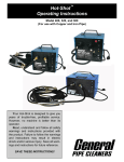
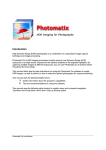
Gen-Eye Micro-Scope™
Video Pipe Inspection/Location System
Operating Instructions
Your Gen-Eye Video Pipe Inspection/
Location System is designed to give you
years of trouble-free, profitable service.
However, no machine is better than its operator.
Read, understand and follow all safety
warnings and instructions provided with the
product. Failure to follow the warnings and
instructions may result in electric shock and/
or serious injury. Save all warnings and instructions for future reference.
SAVE THESE INSTRUCTIONS!
Gen-Eye Micro-Scope™ Video Pipe Inspection/Location System
Electric shock resulting in
death can occur if you plug
this machine into an improperly wired outlet. If the ground
wire is electrified, you can be
electrocuted by just touching
the machine, even when the
power switch is off. A ground
fault circuit interrupter will not protect you in this situation. Use a
UL approved tester to determine
if the outlet is safe.
WARNING! Read and understand all
instructions. Failure to follow all instructions
listed below may result in electric shock, fire
and/or serious personal injury. Replacement
manuals are available upon request at no
charge, or may be downloaded from our website, www.drainbrain.com. Instructional videos
are available for download on our website, and
may be ordered. If you have any questions or
problems, please call General’s customer
service department at 412-771-6300.
Do not operate power tools in
explosive atmospheres, such
as in the presence of flammable liquids, gases, or dust.
Power tools create sparks which
may ignite the dust or fumes.
SAVE THESE INSTRUCTIONS!
These instructions are intended to
familiarize all personnel with the safe
operation and maintenance procedures
for the Gen-Eye Micro-Scope
Video Pipe Inspection/Location System.
Always wear safety glasses
and rubber soled, non-slip
shoes. Use of this safety equipment may prevent serious injury.
SAFETY SYMBOLS
This is the safety alert symbol. It is
used to alert you to potential personal
injury hazards. Obey all safety messages that follow this symbol to avoid
possible injury or death.
DANGER indicates a hazard with a high level of risk
which, if not avoided, will result in death or serious injury.
WARNING indicates a hazard with a medium level of risk
which, if not avoided, could result in death or serious injury.
CAUTION indicates a hazard with a low level of risk which,
if not avoided, will result in minor or moderate injury.
2
Gen-Eye Micro-Scope™ Video Pipe Inspection/Location System
GENERAL SAFETY RULES
WARNING
Read and understand all instructions. Failure to follow all instructions listed below may result in electric shock, fire, and/or
serious injury.
SAVE THESE INSTRUCTIONS!
Work Area
1.
Keep work area clean and well lit. Cluttered benches and dark
areas invite accidents.
2.
Do not operate power tools in explosive atmospheres, such
as in the presence of flammable liquids, gases, or dust.
Power tools create sparks which may ignite the dust or fumes.
3.
2.
5.
Always wear safety glasses and rubber soled, non-slip
shoes. Dust mask, non-skid safety shoes, hard hat, or hearing
protection must be used for appropriate conditions.
6.
Rubber glove inserts should be worn for health and safety
reasons. Sewer lines are unsanitary and may contain harmful
bacteria.
7.
Check to make sure pipes are not electrically hot. In some
cases, ground circuits may be returned to cast iron pipes causing
them to be electrically charged. Care should be taken to check
the entire length on any pipe you are going to inspect.
8.
Prevent object and liquid entry. Never push objects of any kind
into this product through the openings as they may touch dangerous voltage points or short circuit to parts that could result in a
fire or electric shock. Never spill liquid of any kind on the product.
Tool Use and Care
Grounded tools must be plugged into an outlet, properly
installed and grounded in accordance with all codes and
ordinances. Never remove the grounding prong or modify
the plug in any way. Do not use any adapter plugs. Check
with a qualified electrician if you are in doubt as to whether
the outlet is properly grounded. If the tool should electrically
malfunction or break down, grounding provides a low resistance
path to carry electricity away from the user.
Avoid body contact with grounded surfaces such as pipes,
radiators, ranges and refrigerators. There is an increased risk
of electric shock if your body is grounded.
3.
Do not expose power tools to rain or wet conditions. Water
entering a power tool will increase the risk of electric shock.
4.
Do not abuse the cord. Never use the cord to carry the tools
or pull the plug from an outlet. Keep cord away from heat,
oil, sharp edges or moving parts. Replace damaged cords
immediately. Damaged cords increase the risk of electric shock.
5.
Do not overreach. Keep proper footing and balance at all
times. Proper footing and balance enables better control of the
tool in unexpected situations.
Keep bystanders, children, and visitors away while operating a power tool. Distractions can cause you to lose control.
Electrical Safety
1.
4.
When operating a power tool outside use an outdoor extension cord marked “W-A” or “W”. These cords are rated for
outdoor use and reduce the risk of electric shock.
6.
Keep all electric connections dry and off the ground. Reduces the risk of electric shock.
7.
Do not touch plugs or tools with wet hands. Reduces the risk
of electric shock.
1.
Use clamps or other practical way to secure and support the
workpiece to a stable platform. Holding the work by hand or
against your body is unstable and may lead to loss of control.
2.
Do not force tool. Use the correct tool for your application.
The correct tool will do the job better and safer at the rate for
which it is designed.
3.
Do not use tool if switch does not turn it on or off. Any tool
that cannot be controlled with the switch is dangerous and must
be repaired.
4.
Disconnect the plug from the power source before making
any adjustments, changing accessories, or storing the tool.
Such preventative safety measures reduce the risk of starting the
tool accidentally.
5.
Store idle tools out of reach of children and other untrained
persons. Tools are dangerous in the hands of untrained users.
6.
Maintain tools with care. Keep cutting tools sharp and clean.
Properly maintained tools, with sharp cutting edges are less likely
to bind and are easier to control.
7.
Inspect for misalignment or binding of moving parts, breakage of parts, and any other condition that may affect the
tool’s operation. If damaged, have the tool serviced before
using. Many accidents are caused by poorly maintained tools.
8.
Only use accessories that are recommended by the manufacturer for your model. Accessories that may be suitable for
one tool may become hazardous when used on another tool.
Personal Safety
Stay alert, watch what you are doing and use common sense
when operating a power tool. Do not use tool while tired or
under the influence of drugs, alcohol, or medication. A moment of inattention while operating power tools may result in
serious personal injury.
2.
Dress properly. Do not wear loose clothing or jewelry. Contain long hair. Keep your hair, clothing, and gloves away
from moving parts. Loose clothes, jewelry, or long hair can be
caught in moving parts.
3.
Remove adjusting keys or switches before turning the tool
on. A wrench or key that is left attached to a rotating part of the
tool may result in personal injury.
Service
3
1.
Tool service must be performed only by qualified repair personnel. Service or maintenance performed by unqualified repair
personnel could result in injury.
2.
When servicing a tool, use only identical replacement parts.
Follow instructions in the Maintenance section of this manual. Use of unauthorized parts or failure to follow Maintenance
Instructions may create a risk of electric shock or injury.
Gen-Eye Micro-Scope™ Video Pipe Inspection/Location System
SPECIFIC SAFETY RULES
1.
Keep the device out of the reach of children.
2.
Do not look directly into the camera lens at the end of the
probe rod. Your eyesight may be seriously damaged.
3.
Do not forcibly bend, twist or elongate the probe rod.
4.
Strong impact on the device may result in the breakage of
the camera lens at the tip of the insertion tube.
5.
Do not use or store the device at a temperature higher than
140°F (60°C) or lower than -4°F (-20° C).
6.
Store the device in a dry and adequately ventilated environment.
7.
8.
FEATURES
A
B
N
C
O
Keep the device away from acid or alkaline solutions, oil or
petrol, and do not use it in an atmosphere containing their
vapors.
D
E
P
Do not remove the SD Card while data is being saved to the
card. This may cause the data to be lost or the card to be damaged.
F
G
Q
R
9.
Do not use tool if switch does not turn it ON or OFF. Any tool
that cannot be controlled with the switch is dangerous and must
be repaired.
10. Be sure that the unit is plugged into a properly grounded
receptacle. If in doubt, check receptacle before plugging in machine. Check the power cord to see that there are no cuts or
frays, and that the grounding prong on the plug is still in place.
I
S
T
K
H
J
L
M
A.
B.
C.
D.
E.
F.
G.
H.
I.
J.
11. If the power cord supplied with the machine is not long
enough, be sure to use a 16 gauge heavy duty extension
cord no more than 50 feet long and in good condition. Using
lighter cords can result in severe power loss and motor overheating.
13. Be careful when cleaning drains where cleaning chemicals
have been used. Avoid direct contact with corrosive drain cleaners. Drain cleaning chemicals can cause serious burns, as well
as damage the cable. Neutralize or remove corrosive drain
cleaners in the drain before starting the job.
14. Do not operate machine if operator or machine is standing
in water. Will increase risk of electrical shock.
Probe Rod
Command Module
SD Slot
DC-in
Video-out
Microphone
LED Brightness Increase
Zoom Out
PHOTO Button
LED Brightness Decrease
K.
L.
M.
N.
O.
P.
Q.
R.
S.
T.
Mirror Image & Rotate
Escape
POWER Button
USB Port
Speaker
Zoom In
RECORD Button
UP Button
DOWN Button
OK Button
ATTACHMENTS
15. Wear safety glasses and rubber soled, non-slip shoes. Use
of this safety equipment may prevent serious injury.
A
16. Protect against lightening. For added protection for this product during a lightning storm, or when it is left unattended and
unused for long periods of time, unplug it from the wall outlet.
This will prevent damage to the product due to lightning and
power surges.
B
C
17. Protect against excessive heat. The product should be situated
away from heat sources such as radiators, heat registers, stoves,
or other products (including amplifiers) that produce heat.
A. Hook = pick up tool
B. 45° Mirror = gives you a 90° view
C. Magnet = use to pick up metal objects
To use the attachments:
1. Unscrew chrome tip from the end of the Probe Rod and thread
on the desired attachment.
2. Tighten securely before use.
4
Gen-Eye Micro-Scope™ Video Pipe Inspection/Location System
TECHNICAL DATA
SET UP - COMMAND MODULE
Probe Rod & Light Source
Image Sensor
CMOS Image Sensor
Resolution (Dynamic/
Static)
320 (H) x 240 (V) / 640 (H) x 480 (V)
Size Tip (Probe Rod)
Diameter
10 mm
Probe Rod
3 ft. (Extensions Available)
Field of View (FOV)
56 °
Depth of View (DOV)
1.5 cm - 5 cm (OD 5.5 mm/OD 4.0 mm)
Light Source
6 LEDs
Probe Working
Temperature
-4 to 140 °F (-20 to 60°C)
Ingress Protection
IP57
1.
Insert SD card in SD card slot at the side of the display unit. The
metal strips should be facing up for insertion.
2.
Connect the probe rod to
the Command Module, or
the interface cable from
the reel to the Command
Module, as shown and
tighten the locking collar.
3.
Press the POWER button
for 3-5 seconds to turn
the Command Module on.
The Start-up screen is
shown briefly, followed by
the status screen for five
seconds.
The status screen shows the capacity of the SD card and the
internal battery. If the Micro-Scope has been stored for a long
time the display might not have enough power to turn on. Please
use the power adapter to re-charge the battery. Make sure you
plug the power adapter into the port closest to the keypad on the
command module.
MENU SET UP
Command Module
1.
Switch the unit on. Ensure that camera mode is active (i.e. a
“live” picture can be seen).
2.
Press the OK button to access the menus. Use the UP or DOWN
button to select the menu item. Press OK to confirm.
Power
DC5V
Display
3.5” TFT LCD Monitor 320 x 240 Pixels
Interface
Mini USB 1.1/AV out
The options displayed are as follows:
Battery
(Not User Serviceable)
Rechargeable Li-Polymer Battery (3.7V)
Power Adapter
100 - 240 V AC in / 5.5V DC out
Video Out Format
NTSC & PAL
- Delete All
- Video Output
- Date / Time Setup
- Language
Recording Medium
SD card
DELETE ALL:
Compression Format
MPEG4
Still Image Storage
Format
JPEG (640 x 480)
Take care in selecting this option, as everything will be deleted from
the SD card!
Video Recording Format
AVI (640 x 480)
Working & Storage/
Battery Charging
Temperature Range
-4 to 140 °F (-20 to 60°C) /
32 to 104 °F (0 to 40 °C)
Functions
Snapshot, Video Recording, Picture &
Video Review on LCD Screen, TV Out,
Transfer of Picture & Video from SD card
to PC, Digital Zoom
- Video Format
- Auto Power Off
- Input Source
1.
Navigate to DELETE ALL in the menu, press the OK button.
2.
Select YES or NO using the UP or DOWN buttons.
3.
Confirm with the OK button.
VIDEO OUTPUT:
This function allows live pictures or recorded photos and videos to be
displayed on a TV screen.
5
1.
Make sure that the Video format is set correctly to the used TV
system (NTSC or PAL). See the Menu Set Up section.
2.
Connect the scope video cable to the display unit TV out jack.
Ensure that the other end of the video cable is well connected to
the TV.
3.
Press the OK button to select menu options, select Video Output
and press the OK button.
4.
The screen will turn black and the display will be shown on the
TV. You can transfer the screen back to the display unit by selecting the same function.
Gen-Eye Micro-Scope™ Video Pipe Inspection/Location System
DATE/TIME SET UP:
1.
Press UP button & Down button to select month/day/year or
hour/minute/second.
2.
Press PHOTO button to increase the value and the REC button
to decrease the value.
OPERATION
3. The date and time can be displayed in the preview image mode.
Use either the PHOTO or REC button to toggle between display
“ON” and “OFF”.
4. Confirm selection and exit menu by pressing OK.
LANGUAGE SET UP:
1. Navigate to LANGUAGE in the menu, press the OK button.
2. Select the required language using the UP or DOWN buttons.
3. Confirm with the OK button.
VIDEO FORMAT:
1.
2.
3.
1.
Navigate to VIDEO FORMAT in the menu, press OK.
Select the required video format (NTSC or PAL) using the UP or
DOWN buttons.
Confirm with the OK button.
NOTE: The micro push rod is designed to be used in 1-1/2” to 3”
lines ONLY. Do not use it in larger or smaller lines, or you may
damage the push rod.
AUTO POWER OFF:
DO NOT BEND THE PROBE ROD TIP AT AN
ANGLE GREATER THAN 30 DEGREES!
DO NOT BEND THE PROBE ROD WHERE IT
CONNECTS TO THE DISPLAY UNIT!
1. Navigate to AUTO POWER OFF in the menu, press OK.
2. Select the required auto power off time (5, 10, 15, 30 minutes or
Disable) using the UP or DOWN buttons.
3. Confirm with the OK button.
REEL SET-UP
1.
2.
3.
4.
Slowly push the camera into the pipe. Make sure the rod does
not kink or double back on itself.
Mount the handheld Command Module onto
the reel by threading the screw on the monitor mount plate into the back of the handheld unit.
Loosen the knob on the side of the
adjustable monitor mount and set it to
the desired viewing angle, then
tighten.
Connect the interface from the
reel to the connector on top of
the handheld unit.
Press and hold the POWER
button for 3-5 seconds to turn on
the unit.
2.
Once the camera is in the pipe, adjust the lights to a level which
produces the best picture with the least amount of light. To do
this, simply press the LED BRIGHTNESS INCREASE or LED
BRIGHTNESS DECREASE buttons on the display unit.
3.
Push the camera slowly and carefully during the inspection taking note of the pipe condition for possible hazards that may
entangle or damage the camera on entry or retrieval.
4.
When negotiating a corner, care should be taken not to butt the
nose of the camera against the sidewall with any force. It would
be better to let the camera “work” its way around the corner. If
resistance is encountered when turning the corner and there is
no visible signs of blockage, turning the push rod or pulling the
camera back and forth slowly sometimes helps.
AVOID COLLISION OR ANY IMPACT ON THE TIP
OF THE PROBE ROD WHERE THE CAMERA
LENS IS LOCATED!
5.
6
Should resistance become extreme, or the camera gets entangled or stuck, slowly push back and forth to free it. Sometimes
turning the push rod may also help. If the camera is visible you
may be able to free it with your hand or some other means.
Gen-Eye Micro-Scope™ Video Pipe Inspection/Location System
RECORDING THE INSPECTION VIDEO
TRANSFERRING VIDEOS/PHOTOS
TO A PC
NOTE: The Gen-Eye Micro-Scope is equipped with an integral
microphone. The microphone is always on. Therefore, if you are
recording video, please be aware that you are also recording
audio.
1.
Make sure you have established live image on the monitor prior
to recording. Use the ZOOM IN or ZOOM OUT buttons as required to capture the image needed. You can also use the MIRROR IMAGE & ROTATE button to flip or rotate the image as
needed.
2.
Make sure there is an SD card in the SD card reader.
3.
In preview mode, press the REC button to start the recording.
The video icon is shown in the top right corner of the LCD
screen.
4.
To stop recording, press the REC button again. The video icon
disappears. The display reverts to preview mode.
5.
The video is automatically stored to the SD card in AVI format
with a file name of running number. (For example: IMG00001.avi)
6.
You can capture a still photo image during video recording by
pressing the PHOTO button.
Make sure there is an SD card in the SD card reader.
3.
In preview mode, press the PHOTO button to take a photo.
4.
The photo is stored to the SD card in JPG format with a file name
of running number. (For example: IMG0002.jpg)
5.
You can capture a still photo image during video playback and/or
video recording by pressing the PHOTO button.
In the preview mode, press the UP or DOWN buttons. The last
photo or video will be displayed.
2.
Press the UP or DOWN buttons to navigate to the photo or video
to be viewed.
3.
To play a video, press the REC button. Press the REC button
again to pause.
4.
Video volume may be adjusted by pressing the LED BRIGHTNESS INCREASE or LED BRIGHTNESS DECREASE buttons.
5.
To revert to preview mode, press the ESC button.
6.
To delete a saved photo, press the OK button while the photo to
be deleted is displayed.
7.
To delete a saved video, make sure the video is not in play
mode, then press the OK button. A delete menu will appear.
Toggle between the Yes and No options using the UP and
DOWN buttons. Press OK to confirm.
8.
You can capture a still photo image during video playback by
pressing the PHOTO button.
Turn the Gen-Eye Micro-Scope on.
3.
Connect the USB cable to the display unit and the computer.
4.
Look for the drive with the SD card files.
5.
The files can then be transferred and viewed on the PC. Generally speaking, a PC running MS Windows™ 2000 or later should
not require any special software to display the JPG or AVI files.
CAMERA CLEANING
After every use, the camera should be cleaned and checked for possible damage that may have occurred during the inspection. External
scuffing of the camera housing is normal and should be of no concern; however, use the trap skid to protect the camera and help it
slide around elbows more easily.
The camera lens is made of sapphire and should be cleaned with a
soft, damp cloth. Grease, dirt, or scratches will affect the quality of the
video picture.
CABLE AND REEL ASSEMBLY CLEANING
WHEN CLEANING THE REEL ASSEMBLY DO NOT USE A
POWER WASHER. WATER MAY GET INTO UNSEALED AREAS
SUCH AS THE REEL HUB ASSEMBLY AND SLIP RING HOUSING
CAUSING DAMAGE AND VOIDING THE WARRANTY.
The cable and reel assembly should be kept clean from dirt. When
rewinding the cable back onto the reel after an inspection, it is good
practice to use a clean rag to wipe off any debris the cable may have.
REVIEWING VIDEOS/PHOTOS
1.
2.
DISCONNECT MACHINE FROM POWER SOURCE
BEFORE PERFORMING MAINTENANCE ON MACHINE!
Make sure you have established live image on the monitor prior
to recording. Use the ZOOM IN or ZOOM OUT buttons as required to capture the image needed. You can also use the MIRROR IMAGE & ROTATE button to flip or rotate the image as
needed.
2.
Verify that the computer is running MS Windows™ 2000 or later.
MAINTENANCE
TO TAKE A SNAPSHOT
1.
1.
7
Gen-Eye Micro-Scope™ Video Pipe Inspection/Location System
TROUBLESHOOTING
No image on the display after turning the power on:
Battery is exhausted.
Connect the Gen-Eye Micro-Scope to the power adapter supplied and recharge battery. Make sure you have the power adapter
plugged into the correct port - it should be connected to the command module via the port closest to the keypad. (The Micro-Scope
can be used while connected to AC or DC power.)
No image, only words on display after turning the power on:
Check that the Probe Rod or push rod is correctly connected to the display unit.
Unable to record still photos or video:
SD card not present, incorrectly inserted, full or faulty.
Check that an SD card is present and correctly inserted into display unit.
Check SD card capacity.
Check if SD card will work in other devices.
Display unit functions all frozen/failed:
Reboot system
Insert a pin into the hole located on the back of the display unit. The system will restart automatically.
General Wire Spring Co,
1101 Thompson Avenue
McKees Rocks, PA 15136
412-771-6300
www.drainbrain.com
© General Wire Spring Co. 2012
C-GEMSOI-0812