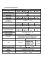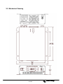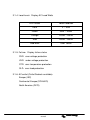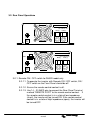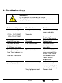
1
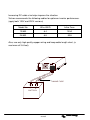
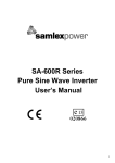
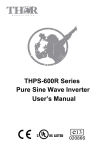
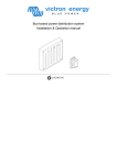
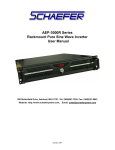
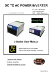
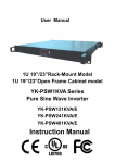
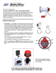
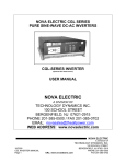
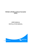
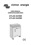
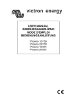
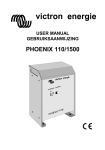
victron energy
USER MANUAL
Phoenix 12/650
Phoenix 24/650
Copyrights © 2005 Victron Energy B.V.
All Rights Reserved
This publication or part thereof, may not reproduced in any form by any method, for any purpose.
VICTRON ENERGY B.V. MAKES NO WARRANTY, EITHER EXPRESSED OR IMPLIED,
INCLUDING BUT NOT LIMITED TO ANY IMPLIED WARRANTIES OF MERCHANTABILITY OR
FITNESS FOR A PARTICULAR PURPOSE, REGARDING THESE VICTRON ENERGY
PRODUCTS AND MAKES SUCH VICTRON ENERGY PRODUCTS AVAILABLE SOLELY ON AN
“AS-IS” BASIS.
IN NO EVENT SHALL VICTRON ENERGY B.V. BE LIABLE TO ANYONE FOR SPECIAL,
COLLATERAL, INCIDENTAL, OR CONSEQUENTIAL DAMAGES IN CONNECTION WITH OR
ARISING OUT OF PURCHASE OR USE OF THESE VICTRON ENERGY PRODUCTS. THE
SOLE AND EXCLUSIVE LIABILITY TO VICTRON ENERGY B.V., REGARDLESS OF THE FORM
OF ACTION, SHALL NOT EXCEED THE PURCHASE PRICE OF THE VICTRON ENERGY
PRODUCTS DESCRIBED HERE IN.
For conditions of use and permission to use this manual for publication in other than the English,
Dutch, French or German language, contact Victron Energy B.V.
Victron Energy B.V. reserves the right to revise and improve its products as it sees fit. This
publication describes the state of this product at the time of its publication and may not reflect the
product at all times in the future.
victron energy
manual
Table of contents
1. Important Safety Information.………………………………………………
1
1-1
General Safety Precautions……………………………………………
1
1-2
Batteries Precautions…………………………………………………..
1
2. Features………………………………………………………………………...
2
2-1
Applications.…………………………………………………………….
2
2-2
Electrical Performance…………………………………………………
3
2-3
Mechanical Drawings…………………………………………………..
4
3. Instructions………………………………………………….…………………
5
3-1
Front Panel Operation..………………………………………………...
5~6
3-2
Rear Panel Operation..…………………………………………………
7~8
3-3
Installation……………………………………………………………….
9
3-4
Quick hook – up and Testing.………………………………………...
10~11
3-5
AC Safety Grounding…………………………………………………..
12~13
3-6
DC Wiring Connections…………………….………………………….
13~14
3-7
Inverter Operation………………………………………………………
15
4. Troubleshooting……….………………………………………………………
16
5. Maintenance……………………………………………………………………
17
victron energy
manual
1. Important Safety Information
WARNING!
Before installing and using the Inverter, you need to read
Following safety information carefully.
1-1. General Safety Precautions
1-1-1. Do not expose the Inverter to water, mist, snow, or dust. To reduce the
risk of hazard, do not cover or obstruct the ventilation shaft.
Do not install the Inverter in a zero-clearance compartment.
Overheating may occur.
1-1-2. To avoid the risk of fire and electronic shock, make sure that existing
wiring is in good electrical condition and not undersize.
Do not operate the Inverter with damaged or substandard Wiring.
1-1-3. There are some components in the inverter can cause arcs and sparks.
To prevent from fire or explosion, do not put batteries, flammable
materials, or anything should be ignition–protected around the inverter.
1-2. Precautions When Working with Batteries
1-2-1. If battery acid contacts your skin or clothing, you need to wash it out
immediately with soap and water. If acid enters into your eyes,
immediately flush your eyes with running cold water for at least 20
minutes and get medical attention immediately.
1-2-2. Never smoke or make a spark or flame in the vicinity of batteries or
Engines.
1-2-3. Do not drop a metal tools on the battery. The resulting spark or shortcircuit on the battery or other electrical parts may cause an explosion.
1-2-4. Remove personal metal items such as rings, bracelets, necklaces, and
watches when working with a lead-acid battery,
A lead-acid battery may produce a short-circuit current who’s
temperature is high enough to weld these metal items and cause a
severe burn.
1
victron energy
manual
2. Features
Pure sine wave output (THD < 3%)
:
Output frequency 50 / 60Hz switch selections
Input & output fully isolated design
High efficiency 88~94%
Driving highly reactive & capacitive load at start moment.
Tri-Color indicators show input voltage & output load level
Loading controlled cooling fan
Advanced microprocessor
:
Protection Input low voltage
Low battery alarm
Overload
Short circuit
Input over voltage
Over temperature
2-1. Applications
2-1-1. Power tools – circular saws, drills, grinders, sanders, buffers, weed and
hedge trimmers, air compressors, etc.
2-1-2. Office equipment – computers, printers, monitors, facsimile machines,
and scanners, etc.
2-1-3. Household appliances – vacuum cleaners, fans, fluorescent and
incandescent lights, shavers, sewing machines, etc.
2-1-4. Kitchen appliances – microwave ovens, refrigerators and freezers,
coffee makers, blenders, ice makers, toasters, etc.
2-1-5. Industrial equipment – metal halide lamp, high – pressure sodium lamp,
etc.
2-1-6. Home entertainment electronics – television, VCRs, video games,
stereos, musical instruments, satellite equipment, etc.
victron energy
manual
2
2-2. Electrical Performance
Model No.
Specification
Item
12/650
24/650
Continuous Output Power
650W
Maximum Output Power (3Min.)
680W
Surge Rating
Input voltage
Output Voltage
12/650
24/650
12V
24V
800W
12V
24V
100 / 110 / 120V
Frequency
+/- 3%
220 / 230 / 240V
50 / 60Hz
(Switch Selections)
+/- 3%
+/- 0.05%
Efficiency (full load)
87.0%
90.0%
90.0%
93.0%
No Load Current Draw
0.87A
0.43A
0.83A
0.43A
Output Waveform
Pure Sine Wave ( THD < 3% )
Output voltage Regulation
100 / 110 / 120V RMS -10%/+4% 220 / 230 / 240V RMS -10%/+4%
Input Voltage Regulation
10.5-15
21.0-30
10.5-15
21.0-30
VDC
VDC
VDC
VDC
Input Level Indicator
Red / Orange / Green
LED
Load Level Indicator
Failure Indicator
Protection
Overload, Short Circuit, Reverse Polarity (Fuse),
Over / Under Input Voltage, Over Temperature.
Safety Certification
UL458
EMC
FCC Class B
Operating Temperature Range
Storage Temperature Range
0 - 33
℃
EN60950-1
EN50081-1: 1992
EN50082-1: 1992
e-mark
EN55022B: 1994
EN61000-4-2: 1995
e13-020866
EN61000-4-3: 1996
ENV50204: 1995
℃ to 70℃
0 - 40
℃
-30
Cooling
Loading controlled cooling fan
Dimensions
295(L) x 180(w) x 72(H) mm / 11.61(L) x 7.09(W) x 2.83(H) Inch
Weight
3
Red LED
2.7 kgs.
/
5.4 Lbs.
2-3. Mechanical Drawing
victron energy
manual
4
3. Instructions
This power inverter series is one of the most advanced line of mobile AC power
systems.
To get the most effective power inverter, it must be installed and used properly.
Please read the instructions of this manual before you install and operate this
model.
:
3-1. Front Panel Operation
:
3-1-1. Front view
P U R E S IN E W A V E IN V E R T E R
3-1-2. ON / OFF switch
:
Leave the switch in the down position (OFF) during installation.
:
3-1-3. Input Level Display Input Voltage
LED Status
DC 12V
DC 24V
Slow Red Blink
10.5~10.9
21.0~21.8
Red
10.9~11.3
21.8~22.6
Orange
11.3~12.0
22.6~24.0
Green
12.0~14.0
24.0~28.0
Orange Blink
14.0~14.7
28.0~29.4
Over Red Blink
14.7
29.4
5
victron energy
manual
:
3-1-4. Load Level Display AC Load Watts
LED Status
Load Condition
Dark
0 ~ 30W
Green
30W ~ 200W
Orange
200W ~ 450W
Red
450W ~ 580W
Red Blink
Over 580W
:
OVP:over voltage protection
UVP:under voltage protection
OTP:over temperature protection
OLP:over load protection
3-1-5. Failure Display failure status
3-1-6. AC outlet (Outlet Sockets available)
:
Europe (IEC)
Continental Europe (SCHUKO)
North America (GFCI)
victron energy
manual
:
3-2. Rear Panel Operation
DC INPUT
WARNING: REVERSE POLARITY
WILL DAMAGE UNIT
NEG(-)
POS(+)
CHASSIS
GROUND
DC INPUT
WARNING: REVERSE POLARITY
WILL DAMAGE UNIT
REMOTE
PORT
NEG(-)
POS(+)
CHASSIS
GROUND
3-2-1. Remote ON / OFF switch for S600R model only.
3-2-1-1. To operate the inverter with Remote ON / OFF switch, ON /
OFF switch on the Front Panel should be off
3-2-1-2. Ensure the remote control contact is off.
3-2-1-3. Use 14 ~ 20 AWG wire to connect the Rear Panel Terminal
marked “REMOTE PORT” to the remote control contact. If
the remote control contact is in a state of low impedance
(short), the inverter will be turned ON. If the remote control
contact is in a state of high impedance (open), the inverter will
be turned OFF.
7
victron energy
manual
3-2-2. Ventilation Shaft
:
Be sure to keep it a distance (at least 1 inch) form surrounding things.
3-2-3. Input terminals
:
Connect the input terminal to 12V / 24V battery or other 12V / 24V
power source.
【+】represents positive, and【-】represents negative. Reverse
polarity connection will blow the internal fuse and may damage the
inverter permanently.
3-2-4. Use wire #8 AWG to connects Chassis ground with Vehicle Chassis.
WARNING!
Operating the inverter without a proper ground
connection may cause an electrical safety hazard.
victron energy
manual
8
:
3-3. Installation
The power inverter should be installed in an environment that meets the
following requirements
:
3-3-1. Dry – Do not allow water to drip on or enter into the inverter.
3-3-2. Cool – Ambient air temperature should be between 0
cooler the better.
℃ and 33℃, the
3-3-3. Safe – Do not install the inverter in a battery compartment or other
areas where flammable fumes may exist, such as fuel storage areas or
engine compartments.
3-3-4. Ventilated – Keep the inverter a distance (at least one inch) away from
surrounding things. Ensure the ventilation shafts on the rear and the
bottom of the unit are not obstructed.
3-3-5. Dust free – Do not install the Inverter in dusty environment.
The dust can be inhaled into the unit when the cooling fan is working.
3-3-6. Close to batteries – Avoid excessive cable lengths. Do not install the
Inverter in the same compartment as batteries.
Use the recommended wire lengths and sizes (see section 3-6).
Do not mount the inverter where it will be exposed to the gases
produced by the battery. These gases are very corrosive, and
prolonged exposure will damage the Inverter.
WARNING!
Shock Hazard. Before proceeding further, carefully
check that the Inverter is NOT connected to any
batteries, and that all wiring is disconnected from any
electrical sources. Do not connect the output terminals
of the Inverter to an incoming AC source.
9
victron energy
manual
:
3-4. Quick hook – up and testing
For a quick hook – up of the power inverter to check its performance
before going ahead with installation, please follow these guidelines
:
3-4-1. To check its performance, unpack and inspect the power inverter the
switch is OFF.
3-4-2. Connect the cables to the power input terminals on the rear panel of
power inverter. The red terminal represents positive (+) and black
terminal represents negative (-). Insert the cables into the terminals
and clamp the nuts and the wires securely.
WARNING!
You may observe a spark when you make this
connection since current may flow into charge
capacitors in the power inverter.
Do not make this connection with the flammable
fumes close by. Explosion or fire may occur.
WARNING!
Ensure all the DC connections are tight (torque to 9 10) ft-lbs, 11.7 – 13 Nm. Loose connections and
overheat may result in a potential hazard.
victron energy
manual
10
3-4-3. Before proceeding further, carefully check that cable you have
connected does tie negative terminal of inverter to the negative output
power source.
CAUTION !
Reverse polarity connection will blow the fuse in
inverter and may permanently damage the inverter.
Damage caused by reverse polarity connection is not
covered by warranty.
3-4-4. Connect the cable from the negative terminal of the inverter to the
negative terminal of the power source. Make a secure connection.
3-4-5. Set the power switch to the “ON” position and the buzzer will send out
beep sound at the moment the inverter will make self-diagnosis and the
LED’s indicators will also appear various colors. Finally the buzzer will
send out another beep sound and the input Level LED indicators will
turn to “Green” color and the inverter starts working successfully.
3-4-6. Set the power switch to OFF position, the inverter stops and all the
lights go Off.
3-4-7. Set power inverter switch to the ON position and turn the test load on.
The inverter should supply power to the load. If you plan to accurately
measure the true output r.m.s. voltage of inverter, a meter such as
FLUKE 45 BECKMAN 4410 or TRIPLETT 4200 must be used.
11
victron energy
manual
:
3-5. AC Safety Grounding
During the AC wiring installation, AC input and output ground wires are
connected to the inverter. The AC input ground wire must be connected to
the incoming ground from AC utility source.
The AC output ground wire should go to the grounding point for your loads
( for example, a distribution panel ground bus ).
3-5-1. Neutral Grounding (GFCI’S)
:
3-5-1-1. 120V models: The neutral conductor of the AC output circuit
of the Inverter is automatically connected to the safety ground
during inverter operation. This conforms to National Electrical
Code requirements that separately derived from AC sources
(such as inverters and generators) which have their neutral
conductors tied to ground in the same way as the neutral
conductors from the utility tied to ground at the AC breaker
panel. For models configured with a transfer relay, while AC
utility power is present and the Inverter is in bypass mode, this
connection (the neutral of the Inverter’s AC output to input
safety ground) is not present so that the utility neutral is only
connected to ground at your breaker panel, as required.
WARNING!
The risk of electronic shock. Use only pass and Seymour
type 2091-W, ground fault circuit-interrupter receptacles.
Other types may fail to operate properly when connected to
this inverter equipment.
:
3-5-1-2. 230V models There is no connection made inside the
Inverter from either the line or neutral conductor to safety
ground.
victron energy
manual
12
Ground Fault Circuit Interrupters (GFCI)
:
Installations in Recreational Vehicles (for North American approvals) will
require GFCI protection of all branch circuit connected to the AC output of
the hardwire terminal equipped with Inverter. In addition, electrical codes
require GFCI protection of certain receptacles in residential installations.
While the pure sine wave output of the Inverter is equivalent to the waveform
provided by utilities, compliance with UL standards requires us to test and
recommend specific GFCI.
Victron has tested the following GFCI – protected 20A receptacles and found
that they functioned properly when connected to the output of the Inverter.
WARNING!
Do not operate the power inverter without connecting
it to ground. Electrical shock hazard may occur.
:
3-6. DC Wiring Connections
Follow this procedure to connect the battery cables to the DC input terminals
on the Inverter. The cables should be as short as possible (less than 10 feet /
3 meters ideally) and large enough to handle the required current in
accordance with the electrical codes or regulations applicable to the
installation.
Cables that are not an adequate gauge (too narrow) or too long will
deteriorate inverter performance such as poor surge capability and frequent
low-input voltage warnings and shutdowns.
These low input voltage warnings are due to DC voltage drop across the
cables from the inverter to the batteries.
The linger and narrower the cables, the greater the voltage drops.
WARNING!
The fuse must be installed on positive cable.
Failure to place a fuse on “+” cables running between
the inverter and battery may cause damage to the
inverter and will void warranty.
13
victron energy
manual
Increasing DC cable size helps improve the situation.
Victron recommends the following cables for optimum inverter performance.
(apply both 120V and 230V versions)
Model No
Wire AWG
Inline Fuse
12/650
#4
100A
24/650
#6
50A
Also, use only high quality copper wiring and keep cable length short, (a
maximum of 3-6 feet).
S600
INLINE FUSE
-
+
BATTERY
victron energy
manual
14
3-7. Inverter Operation
:
To operate the power inverter, use the ON / OFF switch on the Front panel to
turn the power on. Then the power inverter is ready to deliver AC power to
the loads.
If you are operating several loads from the power inverter, turn them on
separately after the inverter is on.
This will ensure that the power inverter does not have to deliver the starting
currents for all the loads at one time.
:
3-7-1. Controls and indicators
The ON / OFF switch turns the control circuit in the power inverter on
and off. It does not disconnect power from the power inverter.
The Inverter operates from an input voltage ranging of
:
10.5 to 15.0 VDC for 12V models
21.0 to 30.0 VDC for 24V models
The Inverter will indicate high and low DC voltage conditions as
follows
:
Model
Dc Input over
Voltage shut-down
Dc Input under
Voltage alarm
Dc Input under
Voltage shut-down
12/650
15.3
11.0
10.5
24/650
30.6
22.0
21.0
15
victron energy
manual
4. Troubleshooting:
:
WARNING!
Do not open or disassemble the inverter.
Attempting to service the unit yourself may cause an
electrical shock or fire.
Problems and Symptoms
Possible Cause
Solutions
Low output voltage
Using average reading
:
(220V:190-210VAC)
Use true RMS reading
meter and cable.
Voltmeter.
Load LED bar flash.
Overload
Reduce load.
No output voltage
Low input voltage.
Recharge battery,
(110V 195-105VAC,
See page 11
3-4-7. of the manual
Voltage indicator
In the lower red zone
No output voltage.
Over Temp indicator on
check connections
and cables.
Thermal shutdown
Improve ventilation,
make sure ventilation
shafts of the inverter
are not obstructed.
Lower ambient
temperature.
Short circuit or Wiring
error.
Check AC wiring
for short circuit or
improper polarity (hot
and neutral reversed).
Remove load.
Load less than 650W
No output voltage
Overload indicator on
Very high power load
victron energy
manual
16
5. Maintenance:
:
Very little maintenance is required to keep your inverter operating properly.
You should clean the exterior of the unit periodically with a damp cloth to pre vent
accumulation of dust and dirt. At the same time, tighten the screws on the DC
input terminals.
17
victron energy
manual
De Paal 35
1351 JG Almere Haven
The Netherlands
T +31 (0)36 5359700
F +31(0)36 5311666
[email protected]
www.victronenergy.com
victron energy
manual