1
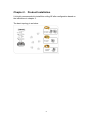
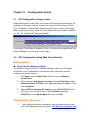
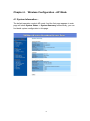
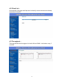
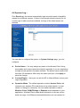
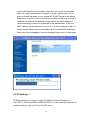
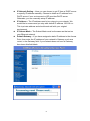
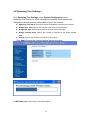
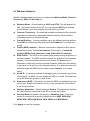
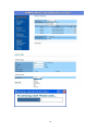
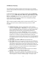
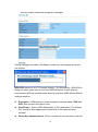
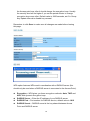
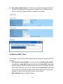
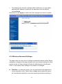
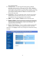
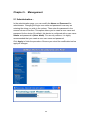
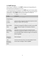
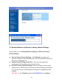
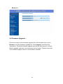
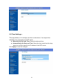
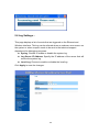
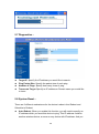
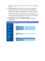
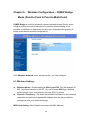
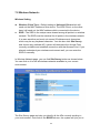
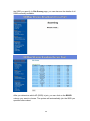
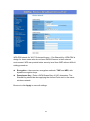
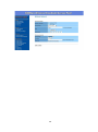
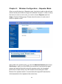
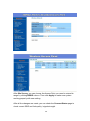
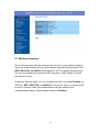
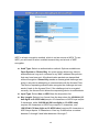
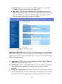
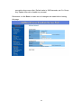
802.11n/b/g Wireless High Power Ceiling Access Point version 1.0 User Manual Contents Chapter 1. Product Overview...................................................................................... 1 1.1 Product Features................................................................................................... 1 1.2 Package Contents ................................................................................................. 1 Chapter 2. Product Installation ................................................................................... 2 Chapter 3. Configuration Guide .................................................................................. 3 3.1 AP Configuration Using Locator ...................................................................... 3 3.2 AP Configuration Using Web User Interface.................................................... 3 Chapter 4. Wireless Configuration - AP Mode ........................................................... 5 4.1 System Information –........................................................................................... 5 4.2 Client List –.......................................................................................................... 6 4.3 Throughput – ........................................................................................................ 6 4.4 System Log – ....................................................................................................... 7 4.5 IP Settings – ......................................................................................................... 8 4.6 Spanning Tree Settings – ................................................................................... 10 4.7 Wireless Network - ............................................................................................ 11 4.8 Wireless Security - ............................................................................................. 13 4.9 Wireless MAC Filter – ....................................................................................... 16 4.10 Wireless Advanced Settings -........................................................................... 17 Chapter 5. Management ............................................................................................ 20 5.1 Administration –................................................................................................. 20 5.2 SNMP Settings– ................................................................................................. 21 5.3 Backup/Restore and Reset to factory default Settings– ..................................... 22 5.4 Firmware Upgrade – .......................................................................................... 23 5.5 Time Settings – .................................................................................................. 24 5.6 Log Settings – .................................................................................................... 25 5.7 Diagnostics –...................................................................................................... 26 5.8 System Reset – ................................................................................................... 26 Chapter 6. Wireless Configuration – Pt(M)P Bridge Mode (Point to Point & Point to Multi-Point).................................................................................................................. 28 6.1 Wireless Setting – .............................................................................................. 28 6.2 Considerations before installation –................................................................... 29 6.3 Wireless Bridge (WDS) Security – .................................................................... 30 Chapter 7. Wireless Configuration – Wireless Client Mode ..................................... 32 7.1 Connection Status - ............................................................................................ 33 7.2 Wireless Network - ............................................................................................ 34 i 7.3 Wireless Security – ............................................................................................ 36 Chapter 8. Wireless Configuration – Repeater Mode ............................................... 39 8.1 Wireless Security – ............................................................................................ 41 ii Chapter 1. Product Overview This wireless indoor AP is an advanced ceiling AP based on 802.11n standard with 300Mbps data rate using MI MO (Multiple In & Multiple Out) technology to increase coverage. There are 4 operation mo des and strong security mechanism for various application demands. 1.1 Product Features Wireless LAN 802.11n and 802.11b/g compliant Support advanced 2T2R Technology with up to 300Mbps Support PoE/PD function (IEEE802.3af/at) Support 64/128bit WEP encryption; WiFi Protected Access(WPA) / WPA2 Wireless Setting Operation Mode: AP / Pt(M)P Bridge / Client / Repeater Support adjustable transmit power by 1dBm Support VLAN & SNMP Support IEEE802.1d Spanning Tree settings Support multiple SSID with 802.1q VLAN tagging (up to 4) Maximum clients 128 (each VLAN supports 32 clients) Support QoS (WMM) and wireless traffic shaping & Time settings 9dBi MIMO antenna Support 48V by external PoE Injector (optional) 1.2 Package Contents The following items are included in the package: Wireless Ceiling AP *1 Bottom plate *1 User Manual CD-R *1 Installation Diagram *1 Screws *4 Plastic wall-plugs *4 48V external PoE Injector (optional) Note: If any of listed items are missing or damaged, please contact the reseller from whom you purchased for replacement immediately. 1 Chapter 2. Product Installation It is highly recommended to install this ceiling AP after configuration based on the instructions in chapter 3. The basic topology is as below: 2 Chapter 3. Configuration Guide 3.1 AP Configuration Using Locator While entering the Locator utility, the Locator will automatically search the AP available on the same network. Locator will show the Device Name, Device Type, IP Address, Ethernet MAC Address and Firmware Version in first page. Before start using Locator, make sure you disable personal firewall installed in you PC. (Ex. Windows XP personal firewall) If you have 2 Fast Ethernet Adapter or more, you can choose enable one Fast Ethernet Adapter for enter with Locator utility. 3.2 AP Configuration Using Web User Interface Before Setup… Verify the IP address setting You need to configure your PC’s network settings to obtain an IP address. Computers use IP addresses to communicate with each other across a network, such as the Internet. 1. 2. 3. Click Start, select Control Panel. Double-click the Network Connections. Right click the Local Area Connection and click Properties; select Internet Protocol (TCP/IP) for the applicable Ethernet adapter. Then click Properties. Select USE the following IP address, enter 192.168.254.254 (but, 192.168.x.x for the device use) in the IP Address field and 255.255.0.0 in the Subnet Mask field, then click OK. Start Setup by Browser... 1. After getting the correct connection, start the web browser (make sure you disable the proxy) and enter 192.168.x.x (x is outdoor unit 3 IP Address) in the Address field. Press Enter. 2. Enter the factory default User name and Password as: User Name: Admin Password: (leave blank) then click OK. 3. You will enter the Utility homepage. Start Setup by Locator... 1. You just need to click on the Web icon in Locator main page. The Locator will launch a default browser for you and lead you into web UI directly. 4 Chapter 4. Wireless Configuration - AP Mode 4.1 System Information – The default operation mode is AP mode. And the first page appears in main page will show System Status -> System Summary automatically, you can find detail system configuration in this page. 5 4.2 Client List – Automatically, this page can help user to identify current devices who already associated to the AP 4.3 Throughput – This page shows the throughput for both LAN and WAN. It refreshes every 5 seconds. 6 4.4 System Log – Click Event Log, the device automatically logs (records) events of possible interest in its internal memory. If there is not enough internal memory for all events, logs of older events are deleted, but logs of the latest events are retained. You can start to configure the system. In System Settings page, you can configure: Device Name – You may assign any name to the Access Point. Using memorable and unique names are helpful, especially if you are employing multiple access points in the same network. The device name needs to be less than 32 characters. After verify the name you input, click Apply to save the change. Country/Region – Here you can set the AP to follow different country and region regulation. Operation Mode - The default operation mode is Access Point, this connects your wireless PCs and devices to a wired network. In most cases, no change is necessary. You can switch operation mode to Wireless Client, Pt(M)P Bridge or Repeater mode depends on your application. Wireless Client mode allows this device to act as a client within its range. Your Ethernet devices behind the unit can connect to 7 remote AP. Repeater mode is able to talk with one remote access point within its range and retransmit its signal. Choose repeater mode if you want to extend the range of your original AP. Pt(M)P Bridge mode allows Bridge point to point or point to multi-point network architecture, In order to establish the wireless link between bridge radios, the MAC address of remotes bridge(s) need to be registered in the address table. Enter the MAC address with format xx:xx:xx:xx:xx:xx (x is the hexadecimal digit). A Master Bridge Radio may accommodate up to 8 remote MAC addresses. Make sure you click Apply to save the changes before move to next page. 4.5 IP Settings – IP Setting page can configure system IP address. Default IP address is 192.168.1.1 and Subnet Mask is 255.255.255.0. You can manually enter the IP address setting or get an IP from a DHCP server. 8 IP Network Setting – Here you can choose to get IP from a DHCP server or specify IP address manually. Choose to obtain an IP address from DHCP server if your environment or ISP provides DHCP server. Otherwise, you can manually setup IP address. IP Address – The IP address need to be unique to your network. We would like to recommend you stay with default IP address 192.168.x.x. This is private address and should work well with your original environment. IP Subnet Mask – The Subnet Mask must be the same as that set on your Ethernet network. Default Gateway – If you have assigned a static IP address to the Access Point, then enter the IP address of your network’s Gateway, such as a router, in the Gateway field. If your network does not have a Gateway, then leave this field blank. 9 4.6 Spanning Tree Settings – Click Spanning Tree Settings under System Configuration menu, Spanning-Tree Protocol is a link management protocol that provides path redundancy while preventing undesirable loops in the network. Spanning Tree Status: Choose to enable or disable the spanning tree feature. Bridge Hello Time: Specify the number of seconds for the hello time. Bridge Max Age: Specify the number of seconds for the max age. Bridge Forward Delay: Specify the number of seconds for the bridge forward delay. Priority: Specify the number of seconds for the priority. Click Apply to save the changes before leaving this page. In Wireless page, each option is described below 10 4.7 Wireless Network Wireless Network page allows you to configure the Wireless Mode, Channel / Frequency, SSID and Security etc. Wireless Mode – Default setting is 802.11g/n HT20. This will support all 802.11g clients connect to the AP. You can choose 802.11g in wireless mode column if your environment only has 802.11g clients. Channel / Frequency –The channels available are based on the country’s regulation and select the appropriate channel from the list provided to correspond with your network settings. Current Profiles – You may configure up to four different wireless profiles. Click Edit to modify the profile and check the Enable box to activate the profile. Profile (SSID) Isolation – Stations connected to different profiles cannot access each other. Choose No Isolation (Full access), or Isolate all profiles (SSIDs) from each other using VLAN (802.1Q) standard. SSID Profile – The SSID is the unique name shared among all points in a wireless network. The SSID must be identical for all points in the wireless network. It is case-sensitive and must not exceed 32 alphanumeric characters, which may be any keyboard character. Make sure this setting is the same for all points in your wireless network. For added security, you should change the SSID from the default name Generic, to a unique name. VLAN ID – If you have enabled VLAN tagging on your network, specify the VLAN tag ID 1 to 4095. You can assign an SSID to a VLAN. Client devices using the SSID are grouped in that VLAN. Suppressed SSID – This option can hide the SSID not available from site survey tool. Enable this function only if you do not want the Access Point to be found by others. Stations Separation – Default setting is Disable. This option can disallow the client devices connected to this AP to access each other. Security Mode: By default, the security is Disabled. Refer to the next section to configure the security features such as WEP, WPA-PSK, WPA2-PSK, WPA-PSK Mixed, WPA, WPA2 and WPA-Mixed. Click Apply to save the changes. 11 12 4.8 Wireless Security The wireless security settings configure the security type of your wireless network. There are different wireless security mode options supported by the Access Point. In Wireless Security page, you can configure the AP to work with Disabled (means no security), WEP, WPA-PSK, WPA2-PSK, WPA-PSK Mixed, WPA, WPA2 and WPA-Mixed mode. Once you setup the AP to work in security mode, all wireless stations will also need to have corresponding settings. System default setting is Disabled. WEP is a basic encryption method, which is not as secure as WPA. To use WEP, you will need to select a default transmit key and a level of WEP encryption. Authentication Type: Select an authentication method. Options available are Open System or Shared Key. An open system allows any client to authenticate as long as it conforms to any MAC address filter policies that may have been set. All authentication packets are transmitted without encryption. Shared Key sends an unencrypted challenge text string to any device attempting to communicate with the Access Point. The device requesting authentication encrypts the challenge text and sends it back to the Access Point. If the challenge text is encrypted correctly, the Access Point allows the requesting device to authenticate. Input Type: Select Hex or ASCII from the drop-down list. Key Length: Select a key format from the drop-down list. 40/64bit-hex keys require 10 characters or ASCII keys require 5 characters, where as 104/128-bit-hex keys require 26 characters or ASCII keys require 13 characters, as 128/152-bit-hex keys require 32 characters or ASCII keys require 16 characters. A hex key is defined as a number between 0 through 9 and letter between A through F. Default Key: You may use up to four different keys for four different networks. Select the current key that will be used. Key table – You can enter 4 different WEP encryption keys into the table and by choosing the radio button to decide which one is valid now. The AP supports 64, 128 and 152bit key length. The longer key we 13 choose usually means the encryption is stronger. After all changes are made, click Save to make sure all changes are saved into system. WPA-PSK stands for Wi-Fi Protected Access – Pre-Shared Key. WPA-PSK is design for home users who do not have RADIUS server in their network environment. WPA can provide better security level than WEP without difficult setting procedure. Encryption - WPA gives you three encryption methods: Auto, TKIP and AES, with dynamic encryption keys. PassPhrase - Enter a WPA Shared Key of 8-63 characters. The Shared Key should be also applying the clients work in the same wireless network. Group Key Update Interval - Enter a number of seconds which instructs 14 the Access point how often it should change the encryption keys. Usually the security level will be higher if you set the period shorter to change encryption keys more often. Default value is 3600 seconds, set 0 in Group Key Update Interval to disable key renewal. Remember to click Save to make sure all changes are made before leaving this page. WPA option features WPA used in coordination with a RADIUS server (this should only be used when a RADIUS server is connected to the Access Point). Encryption – WPA gives you three encryption methods: Auto, TKIP and AES, with dynamic encryption keys. RADIUS Server – Enter the IP address of your RADIUS server. RADIUS Port – Port number for RADIUS service, default value is 1812 RADIUS Secret – RADIUS secret is the key shared between Access Point and RADIUS server. 15 Group Key Update Interval – This column indicate how often should the Access Point change the encryption key. Default value is 3600 seconds, set 0 in Group Key Update Interval to disable key renewal. 4.9 Wireless MAC Filter – In this page, you can filter the MAC address by allowing or blocking access the network. ACL (Access Control) Mode: You may choose to Disabled, Deny MAC in the List, or Allow MAC in the List. By selecting Allow MAC in the List, only the address listed in the table will have access to the network; all other clients will be blocked. On the other hand, selected Deny MAC in the List means only the listed MAC addresses will be blocked from accessing the network; all other clients will have access to the network. MAC Address: Enter the MAC address. 16 This table lists the blocked or allowed MAC addresses; you may delete selected MAC address or delete all the addresses from the table by clicking Delete. Remember to click Apply to make sure all the changes are saved to system. 4.10 Wireless Advanced Settings The page below can help users to configure advanced wireless setting. Before making any changes in this page, please check your wireless settings on other system as well, as these changes will alter the effectiveness of the Access Point. In most cases, these settings do not need to be changed. Data Rate – In data rate column, you can select all bit rate supported in current operation mode. Default value is Auto which means the system will automatically adjust the connection speed dynamically according to 17 your current link status. Transmit Power – You can reduce RF output power by selecting adjustable transmit power by 1dBm step from 28 to 3 dBm. Changing transmit power may decrease your wireless signal coverage. This feature can be helpful in restricting the coverage area of the wireless network. You can arrange the different data rate in distance in Access Point mode. Please refer below table. Aggregation – When you enable this function, the device will combine several packets and then transmit them as one. This is to reduce the overhead when there are large packets to be transmitted. WMM – Choose to Enable or Disable wireless multimedia mode. Distance (1-30km) – Setup this parameter according to the longest link distance between the point to point, or point to multi-point in the network. The input needs to be greater than or equal to the real distance. The range can be from 1km to 30km. Wireless Traffic Shaping – Choose to enable or disable wireless traffic shaping, specify the incoming and outgoing transmission limit kbit/s. Remember to click Apply to make sure all changes are made before leaving this page. 18 19 Chapter 5. Management 5.1 Administration – In the administration page, you can modify the Name and Password for administrator. Changing the login user name and password is as easy as entering the string you wish in the column. Then enter the password in the second column to confirm. This option allows you to create a user name and password for the device. By default, this device is configured with a user name Admin and password is (leave blank). For security reasons, it is highly recommended that you create a new user name and password. Click Apply to finish the procedure. Be sure you noted the modification before apply all changes. 20 5.2 SNMP Settings– Under System Configuration, click SNMP to display and change settings for the Simple Network Management Protocol. To communicate with the access point, the SNMP agent must first be enabled and the Network Management Station must submit a valid community string for authentication. Select SNMP Enable and enter data into the fields as described below. Click Apply to save the changes. Setting Description SNMP Enable/Disable Enables or disables SNMP. Contact Location Sets the location string that describes the system location. Maximum length is 255 characters. Community Specifies a community string with read-only access. Name (Read Only) Authorized management stations are able to retrieve MIB objects. Maximum length is 32 characters. Default is public. Community Name (Read/ Write) Specifies a community string with read-write access. Authorized management stations are able to both retrieve and modify MIB objects. Maximum length is 32 characters. Default is private. Trap Destination IP Address Enter the IP address of the trap manager that will receive these messages. Trap Enter the community name of the trap manager that will Destination Community Name receive these messages. Default is public 21 5.3 Backup/Restore and Reset to factory default Settings– In this section, you can Backup/Restore Setting and Revert to Factory Default Settings: Save A Copy of Current Settings – Click Backup, the system will prompt you where to save the backup file. You can choose the directory to save your configuration file. Restore Saved Settings from A File – Here you can restore the configuration file from where you previously saved. Revert To Factory Default Settings – Be very carefully before restore system back to default since you will lose all current settings immediately. If you act the function, the IP address will restore the establishing value situation. 192.168.1.1 in the IP Address field and 255.255.255.0 in the Subnet 22 Mask field, 5.4 Firmware Upgrade – Enter the location of the firmware upgrade file in the file path field, or click Browse to find the firmware upgrade file. Click Upgrade, and follow the instructions. The whole firmware upgrade process will take around 1 minute. Before upgrade, make sure you are using correct version. Please check with your technical support service if new firmware available. 23 5.5 Time Settings – This page allows you to configure the time on the device. You may do this manually or by connecting to a NTP server. Manually Set Date and Time: Setup the date and time Automatically Get Date and Time: Select the time zone from the drop down list and then specify the IP address of the NTP server. Click Apply to save the changes. 24 5.6 Log Settings – This page displays a list of events that are triggered on the Ethernet and Wireless interface. This log can be referred when an unknown error occurs on the system or when a report needs to be sent to the technical support department for debugging purposes. Syslog: Choose to enable or disable the system log. Log Server IP Address: Specify the IP address of the server that will receive the system log. Local Log: Choose to enable or disable the local log. Click Apply to save the changes. 25 5.7 Diagnostics – Target IP: Specify the IP address you would like to search. Ping Packet Size: Specify the packet size of each ping. Number of Pings: Specify how many times of ping. Traceroute Target: Specify an IP address or Domain name you would like to trace. 5.8 System Reset – There are 2 different mechanisms for the device t reboot: Auto Reboot and Schedule to Reboot. Auto Reboot: When you enable this function, you will need to specify an IP address which you want this device to ping. This IP address could be another wireless device, a server or any device with IP address. And you 26 can decide the time period (in seconds) or the failure counts to trigger this function. Schedule to Reboot: This function is used when there are large data communicating in your network which may cause system unstable as sometimes the buffer memory on different devices such as the Access point, IP camera, switch, or computer would run out and you may find the fastest way to get the whole system back to work by unplug the power (any device) and power it up again. This is because the buffer memory will be released when you unplug the power. Thus, you may use this function to specify a time that you want this device to reboot. Reboot Now: you can choose to Reboot the Device or Restore to Factory Default. 27 Chapter 6. Wireless Configuration – Pt(M)P Bridge Mode (Point to Point & Point to Multi-Point) Pt(M)P Bridge is used for wirelessly connect several Access Points, and in doing so extend a wired infrastructure to locations where cabling is not possible or inefficient to implement (be sure you understand the purpose of bridge mode before proceed configuration). Click Wireless Network under Wireless menu, you can configure: 6.1 Wireless Setting – Wireless Mode – Default setting is 802.11g/n HT20. This will support all 802.11g clients connect to the AP. You can choose 802.11g in wireless mode column if your environment only has 802.11g clients. Channel / Frequency –The channels available are based on the country’s regulation and select the appropriate channel from the list provided to correspond with your network settings. WDS Link Setting: Select Enable and enter the MAC address. 28 6.2 Considerations before installation – Loop Prevention – Be careful to plan you Wireless Bridge connections, prevent your wireless network topology to have loop. Once loop shows up, you network traffic will become unstable. Performance – The system can support up to 8 Wireless Bridge links. But all links and wireless stations that operate at the same time will all share single radio bandwidth (Ex. 11g have 54Mbps bandwidth). Latency – In the chain topology configuration, if the chain becomes very long, end-to-end latency issue may come in play. We suggest the Bridge link topology planning should not exceed 2 hops in chain configuration. 29 6.3 Wireless Bridge (WDS) Security – Wireless Bridge (WDS) now only supports limit wireless security protocol. Here lists Wireless Bridge (WDS) security settings below: None – Both Point to Point and Point to Multi-Point traffic transmit without encryption. AES – Both Point to Point and Point to Multi-Point traffic are encrypted by the same AES key. 30 After all changes are made, click Apply to save into system. 31 Chapter 7. Wireless Configuration – Wireless Client Mode This device can also work as a client device. In order to setup this device to work in such mode, you need to choose Wireless Client mode and click Apply. After the system reboot is done, you can see the page as below. Status page show the device is now working in Wireless Client mode. 32 7.1 Connection Status This column show current connection status. If this device already connects to an Access Point or station, here will show the MAC address of the associated Access Point or station. Otherwise, connection column will show N/A which means no connection to any Access Point or station. Wireless Client Type – Here indicates the information of this device. SSID – SSID column displays current SSID assigned to the AP. BSSID – Basic Service Set Identifier. This is the assigned MAC address of the station in the access point. Connection Status – Showa the current status Associated or N/A. Wireless Mode – Shows the Access Point current work in either 11g or 11n mode. Current Channel – This column indicates the radio channel currently in use. Security – Indicates AP security settings in client mode. Should be either Disabled, WEP or WPA-PSK. Tx Data Rate(Mbps) – Shows the current Tx Data rate status. Current noise level –This column shows current link quality with AP by noise level in 0 to -96 dBm scale. Signal strength – This column shows current link quality with AP by signal strength in 0 to -96 dBm scale. 33 7.2 Wireless Network Wireless Setting Wireless Client Type – Default setting is Universal Client which will send out the MAC address of this device. The WDS Client, on the other hand, will send out the MAC address which connected to the device. SSID - The SSID is the unique name shared among all points in a wireless network. The SSID must be identical for all points in the wireless network. It is case-sensitive and must not exceed 32 alphanumeric characters, which may be any keyboard character. You can also click Site Survey and choose any available AP; system will determine the Access Point currently available and establish connection with that Access Point. If you already understand your wireless environment well, you can enter the SSID in manually. In Wireless Network page, you can find Site Survey button as shown below. You can click on it to find all wireless networks available in your current environment. The Site Survey page can help you identify all the APs currently working in your environment. Just click on the BSSID column, the system will join you to 34 the SSID you specify. In Site Survey page, you can also see the details of all SSIDs currently available. After you determine which AP (SSID) to join, you can click on the BSSID column your want to choose. The system will automatically join the SSID you specified after reboot. 35 7.3 Wireless Security – WEP is a basic encryption method, which is not as secure as WPA. To use WEP as a client, you will need to enter a transmit key and a level of WEP encryption exactly the same as the Access Point. Auth Type: Select an authentication method. Options are Open System or Shared Key. An open system allows any client to authenticate as long as it conforms to any MAC address filter policies that may have been set. All authentication packets are transmitted without encryption. Shared Key sends an unencrypted challenge text string to any device attempting to communicate with the Access Point. The device requesting authentication encrypts the challenge text and sends it back to the Access Point. If the challenge text is encrypted correctly, the Access Point allows the requesting device to authenticate. Input Type: Select Hex or ASCII from the drop-down list. Key Length: Select a key format from the drop-down list. 40/64bit-hex keys require 10 characters or ASCII keys require 5 characters, where as 104/128-bit-hex keys require 26 characters or ASCII keys require 13 characters, as 128/152-bit-hex keys require 32 characters or ASCII keys require 16 characters. A hex key is defined as a number between 0 through 9 and letter between A through F. Default Key: You may use up to four different keys for four different networks. Select the current key that will be used. Key table – You can enter 4 different WEP encryption keys into the table and by choosing the radio button to decide which one is valid now. The AP supports 64, 128 and 152bit key length. The longer key we choose usually means the encryption is stronger. Be sure to click Apply to save all settings. 36 WPA-PSK stands for Wi-Fi Protected Access – Pre-Shared Key. WPA-PSK is design for home users who do not have RADIUS server in their network environment. WPA can provide better security level than WEP without difficult setting procedure. Encryption – there are two encryption methods: TKIP and AES, with dynamic encryption keys. Passphrase Key - Enter a WPA Shared Key of 8-63 characters. The Shared Key should be also applying the Access Point work in the same wireless network. Be sure to click Apply to save all settings. 37 38 Chapter 8. Wireless Configuration – Repeater Mode When you set the device to Repeater mode, the device is able to talk with one remote access point within its range and retransmit its signal. In order to setup the device to work in such mode, you need to choose Repeater and click Apply in System Settings page. Please reboot the device to make sure it works in repeater mode. After enable the repeater mode, you can click Wireless Network and choose Site Survey to pick one of the SSIDs you would like to retransmit its signal (please be awarded that while using the repeater mode, the throughput performance maybe nearly only half compare with access point mode. Because the repeater needs to communicate with original AP and also the clients associate to the repeater at the same time). 39 After Site Survey, you can choose the Access Point you need to extend its range by clicking BSSID column. Then click Apply to make sure system working properly with new setting. After all the changes are made, you can check the Connect Status page to check current SSID and link quality / signal strength. 40 8.1 Wireless Security – The wireless security settings configure the security of your wireless network. There are three wireless security mode options supported by the Access Point: WEP, WPA-PSK, and WPA2 (WPA stands for Wi-Fi Protected Access, which is a security standard stronger than WEP encryption. WEP stands for Wired Equivalent Privacy). In Wireless Security page, you can configure the AP to work with Disabled (no Security), WEP, WPA-PSK, and WPA2 security mode. Once you setup the AP to work in security mode, all wireless stations will also need to have corresponding settings. System default setting is Disabled. 41 WEP is a basic encryption method, which is not as secure as WPA. To use WEP, you will need to select a default transmit key and a level of WEP encryption. Auth Type: Select an authentication method. Options available are Open System or Shared Key. An open system allows any client to authenticate as long as it conforms to any MAC address filter policies that may have been set. All authentication packets are transmitted without encryption. Shared Key sends an unencrypted challenge text string to any device attempting to communicate with the Access Point. The device requesting authentication encrypts the challenge text and sends it back to the Access Point. If the challenge text is encrypted correctly, the Access Point allows the requesting device to authenticate. Input Type: Select Hex or ASCII from the drop-down list. Key Length: Select a key format from the drop-down list. 40/64-bit (10 hex digits or 5 ACSII char) require 10 characters or ASCII keys require 5 characters, while 104/128-bit (26 hex digits or 13 ACSII char) requires 26 characters or ASCII keys require 13 characters, and 128/152-bit (32 hex digits or 16 ACSII char) requires 32 characters or ASCII keys require 16 characters. A hex key is defined as a number between 0 through 9 and letter between A through F. 42 Default Key: You may use up to four different keys for four different networks. Select the current key that will be used. Key table – You can enter 4 different WEP encryption keys into the table and by choosing the radio button to decide which one is valid now. The AP supports 64, 128 and 152bit key length. The longer key we choose usually means the encryption is stronger. Be sure to click Apply to save all changes. WPA-PSK / WPA2-PSK stands for Wi-Fi Protected Access – Pre-Shared Key. WPA-PSK is design for home users who do not have RADIUS server in their network environment. WPA can provide better security level than WEP without difficult setting procedure. Encryption - WPA gives you three encryption methods: Auto, TKIP and AES, with dynamic encryption keys. PassPhrase - Enter a WPA Shared Key of 8-63 characters. The Shared Key should be also applying the clients work in the same wireless network. Group Key Update Interval - Enter a number of seconds which instructs the Access point how often it should change the encryption keys. Usually the security level will be higher if you set the period shorter to change 43 encryption keys more often. Default value is 3600 seconds, set 0 in Group Key Update Interval to disable key renewal. Remember to click Save to make sure all changes are made before leaving this page. 44