1
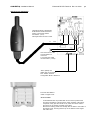
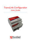
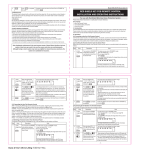
CONCEPT IQ. Installation Manual.
Enhanced RF LED Terminal. Rev 1.0 05/03
Enhanced RF LED Terminal
p1
995500V2RF
The Enhanced RF LED Terminal is a versatile operator interface for the Concept IQ system providing standard LED
Terminal functions along with an interface for the Inner Range Wireless Keyfob Remote Control. The Terminal provides
status display of up to 16 Zone Inputs and 4 Areas along with indication of “Power”, “Fault”, “Home Mode” and “Armed”
conditions.
Audible button press feedback is provided and the built-in Beeper also provides indication of Alarms, Entry/Exit warnings,
Auto-Arm warning, User Operation OK and User Operation Unsuccessful.
While the system can be programmed via Upload/Download software, the Terminal also provides the ability for the
Installer to program all system parameters.
In addition to these standard functions, the RF Enhanced Terminal also provides an interface for the Concept IQ RF
Remote Receiver. Up to 6, Four button Keyfob Remotes can then be programmed to:
- Arm and Disarm the Areas in the User’s Area List.
- Turn Auxiliary 2 on the Control Module On and Off.
- Activate a Panic alarm by pressing any 2 keys simultaneously.
IMPORTANT NOTES:
1)
Four Button Keyfob Remotes (P/N 995508) are purchased separately.
2)
The Enhanced RF Terminal DOES NOT provide Door Access Control functions.
Enhanced RF LED Terminal PARTS LIST.
-
Concept IQ Enhanced RF LED Terminal.
910043 Mounting Backplate.
995509 RF Receiver
625500 Zone List Label.
Installation manual. (This document)
SPECIFICATIONS.
Dimensions.
Weight:
Installation Environment.
Continuous Operating Temp:
Storage Temperature:
Relative Humidity:
Length. 132mm
150 grams.
Operating voltage:
Current consumption:
11V to 14V DC.
Standby. 32mA.
RF Receiver. (Part No. 995509)
Dimensions:
Current Consumption:
Length. 110mm
7.5mA
Width. 85mm
Depth. 28mm
0 to +50 °C
-20 to +70 °C
15% to 85% Non-condensing.
50mA with 8 LEDs On.
Width. 30mm
Depth. 10mm
LAN CABLING CONSIDERATIONS.
The Enhanced RF Terminal is one of a number of different types of Concept IQ LAN Modules. A maximum of 4 LAN Modules
can be connected to the system LAN. Other types of LAN Modules are Standard and Enhanced LED Terminals and RF
Modules.
-
Recommended cable is 4 core or 6 core security cable 14/0.20. (NOT twisted pair. Twisted pair cable [e.g. Category 5]
may be used, however, DO NOT combine “Clock” & “Data” on the same pair.)
Do not apply power to cable until all connections are made and checked.
Maximum cabling distance from the Control Module to the furthest Module must not exceed 100 metres.
Maximum total LAN cabling in the system must not exceed 150 metres.
DO NOT connect the “CLK” & “DATA” wires to the Control Module until all LAN Modules (e.g. Terminals) are Commissioned.
(See Commissioning Instructions)
Disclaimer: While every effort has been made to ensure the accuracy of this manual, the manufacturer assumes no
responsibility or liability for any errors or omissions. Due to ongoing development, this manual is subject to change without
notice.
©
2003. Inner Range Pty. Ltd.
Part No: 635500RF
p2
Enhanced RF LED Terminal. Rev 1.0 05/03
INSTALLATION.
CONCEPT IQ. Installation Manual.
Connection diagrams provided on the next page.
Enhanced RF Terminal installation.
-
-
The Terminal must be installed on a flat, vertical surface in an appropriate location. Ensure that the display will be at, or
slightly below eye level, for all Users.
Remove the rear mounting plate from the back of the Terminal.
Cut suitable holes in the mounting surface for cable entry and the fasteners. (The rear mounting plate can be used as a
template)
NOTE: The Terminal is also designed to be mounted on plasterboard/gyprock surfaces using a standard switch plate
Mounting Clip. e.g. Clipsal 154 or HPM 712.
The rear mounting plate can now be installed using appropriate fasteners through the holes provided. Remember to
insert the LAN cable and other wiring through the cable entry cutout first.
Connect the LAN wiring into the Screw Terminal block T2.
Clip the Terminal onto the rear mounting plate by first locating the tongue at the top of the Terminal into the slot
provided by the rear mounting plate, then clip the bottom of the Terminal into place.
ACCESS TO THE TERMINAL PCB IS REQUIRED FOR RF RECEIVER WIRING AND COMMISSIONING. (INCLUDES
ENROLLING THE REMOTES) DO NOT CLIP THE TERMINAL ONTO THE REAR MOUNTING PLATE UNTIL ALL WIRING
AND COMMISSIONING IS COMPLETED.
RF Receiver Installation.
-
-
Install the RF Receiver (Part No. 995509) in a suitable location not more than 10 metres cabling distance from where
the Enhanced RF Terminal is installed.
NOTE: A 2 metre cable is supplied with the RF Receiver. If convenient, it is recommended that the Receiver is installed
within 2 metres cabling distance from the RF Terminal.
If the cabling distance is greater than 2 metres, an additional length of cable will be required to extend the length of the
supplied cable. 4 core security cable is recommended.
Remove the 4 way connector on the flying end of the cable by cutting the wires close to the connector. This will leave
approximately 30mm flying leads for connection to the Terminal.
Strip 5mm of insulation from the Red, Black and Brown wires to prepare for termination and route the cable to the
Enhanced RF Terminal. (The Blue wire is not used)
Terminate the Red, Black and Brown wires into the +LAN, 0V and Zone1 connections respectively, as shown in the
diagram opposite.
Other connections.
-
The “Zone2” Input and “Aux1” Output are not utilized on RF Enhanced Terminals at this time.
ADDRESSING & COMMISSIONING (Read “LAN cabling considerations” first)
1. Enable Terminal Configuration Mode.
Method 1:
-Remove power from the Terminal.
-Hold down the <NEXT> and <HOME> keys.
-Re-apply power to the Terminal.
-Release the <NEXT> and <HOME> keys.
Method 2:
-Hold down the <NEXT> and <HOME> keys.
-Short the “RST” (Reset) link on the rear of the Terminal. (See diagram on Page 3)
-Release the <NEXT> and <HOME> keys.
2. Note the current Address setting. The current Address of the Terminal will be displayed via the Zone 1 to 4 Lamps.
-The Zone Lamp number that corresponds to the current Address will flash.
3. Select the new Terminal Address number.
-Press the key that corresponds to the required Address (1 to 4) within 10 seconds, then press <ENTER>.
4. Check that the current Door Alarm status is Disabled.
-After the Terminal Address has been entered as per Step 3, the display will now show the current Door Alarm enable
status:
0 = Disabled (Default)
1 = Enabled
-If the Door Alarm status is Enabled, press the <0> key within 10 seconds to Disable.
5. Enter RF Remote Keyfob enrolling mode.
-While the Door Alarm status is being displayed, Press the <2> key within 10 seconds to enter RF Remote Keyfob
enrolling mode.
-All 4 of the Area LEDs will flash to indicate that programming mode is enabled.
CONCEPT IQ. Installation Manual.
Enhanced RF LED Terminal. Rev 1.0 05/03
p3
INSTALLATION DIAGRAMS
If extending the length of cable between
the RF Receiver and the RF Enhanced
Terminal, 4 Core Security Cable is
recommended. (14/0.2)
Total length must be less than 10 metres.
0V
Data
+LAN
Black
Brown
Red
LAN connections to the
Control Module T4
connector.
4 Core Security Cable
recommended. (14/0.2)
“RST” (Reset) link.
(Either link can be used)
See “Enable Terminal
Configuration Mode. Method 2”
Zone List label fitted to
inside of keypad cover.
Zone List Label.
-
A self-adhesive label is provided that can be used to provide Area
and Zone information and Emergency alarm activation instructions.
If required, neatly print the names of any Areas and Zones used in
the system in the spaces provided on the label.
Remove the backing sheet and carefully affix the label to the inside of
the keypad cover, ensuring that the top of the label is at the hinged
end of the cover.
p4
CONCEPT IQ. Installation Manual.
Enhanced RF LED Terminal. Rev 1.0 05/03
6. Enrol the Remote Keyfobs into the Terminal.
a) Press any key on the first Remote to be enrolled.
The Terminal will emit a short beep to acknowledge that the Terminal has received the data.
b) Press the same key on the Remote again to confirm the data.
After successfully receiving the Remote Keyfob data twice (Through Steps a & b), the Terminal will emit a long beep to
confirm that the enrolment was accepted.
7. a) Enrol additional RF Remote Keyfobs.
-Repeat step 6 to enrol up to 5 additional Remotes. (A total of 6 Remotes can be enrolled)
b) Erasing RF Remote Keyfobs.
-Press the <9> key at any time while in RF Remote Programming mode to erase all Remotes.
NOTES:
1. When 6 Remotes have been enrolled into the Terminal, enrolling any additional Remotes will always overwrite the
last Remote that was enrolled. i.e. The first 5 Remotes enrolled will not be affected.
2. If the RF Terminal does not receive any data from a Remote for 60 seconds, the Terminal will automatically exit
Terminal Configuration Mode.
3. Any Remote that has been enrolled on an RF Terminal cannot perform any operations until it is assigned to a User.
See Step 10 below. “Program the RF Remote operations”.
-When the <ENTER> key is pressed, the Enhanced Terminal will exit Terminal Configuration Mode.
8. Initialize the LAN. If a new Terminal is added to an existing system, once the Terminal is configured and connected
to the system LAN, the LAN must be initialized by Removing and Re-applying power to the Control Module.
Remember to disconnect the battery also when removing power.
9. Area Assignment. RF Enhanced Terminals must be configured for Single Area Mode by defining an “Associated Area”
for the Terminal (Addresses 561 [Terminal 1] to 564 [Terminal 4] ). See the Programming Manual.
10. Program the RF Remote Operations for a USER. (Adding or Changing a User)
NOTE RF keyfobs can only be assigned to a USER on “Terminal 1”
Logon.
Enter your PIN code;
...
Select the first User number to be added or changed.
Press
,
,
,
. Where
is the User number
The <A1> Lamp will flash to indicate the system is ready for the PIN Code or Wireless Remote Key entry.
If a PIN code is already programmed for this User, the corresponding number of Zone Lamps (4 or 6) will be flashing.
Enrol the User’s Wireless Remote Key.
Press a button on the Remote Key within 30 seconds of selecting the User number.
Three short beeps will sound to confirm that the Remote Key has been enrolled and assigned to the selected User.
If the Remote Key is already assigned to another User, or is not recognised by the system, one long beep will sound to
indicate a problem.
Enter the new PIN Code (may not be required)
A Zone Lamp (1 to 4, OR 1 to 6) will Fast flash to indicate which digit of the PIN code is to be entered.
As each digit is entered, 3 very short beeps will sound to indicate that the entry is accepted, and the next Zone Lamp will
now Fast flash for the next digit to be entered.
... (4 or 6 digits), then press
Enter the new PIN number
Three short beeps will sound to confirm the new PIN number has been programmed, -If the PIN is rejected, one long
beep will sound to indicate a problem.
Assign or Change the User Area or Areas. (Only required if you have a Multi-Area System)
The <A2> Lamp will flash to indicate the system is ready for the Area assignment entry.
The corresponding Zone Lamps (1 to 4) will indicate the Area/s selected.
Press the Area number
for each Area that is to be Assigned or Un-assigned to this User..
When the required Areas have been Selected and/or De-selected, press
.
NOTE: Each User programmed into the system can have an RF Remote OR an Access Card assigned, but not both.
If a person requires both of these items, program two Users into the system for that person. Set the options exactly the
same for both Users and assign the RF Remote to one of them, and the Access Card to the other.
User Programming can be found in the Programming manual, or in the User’s manual.