1
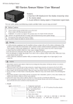
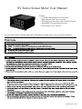
SV Series Sensor Meter User Manual
Features:
⊙TC/RTD/Analog Signal Universal Input;
⊙Multi Display Units can be choosed;
⊙With Display, Alarm and Current Transmit function;
⊙With RS485 Communication Function;
⊙Power Supply: 100--240VAC
For your safety, please read following Notice Information carefully before you are using our product!!
S
KKSV8WE01-A/0-1
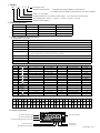
1. Model
SV □ □ □ □ W
W: Design Code
Input & Communication:
10: Single Input without RS485 Communication
18: Single Input with RS485 Communication (should be ordered)
Alarm: C: Two Alarm
Output Function: R: No 4-20mA current output; D: 4--20mA DC current output
Size (W*H)mm: 4: 48*48 6: 48*96 7: 72*72 8: 96*48 9: 96*96
SV Series Sensor Meter
2. Model Indication
Model
SV□-RC10W
Alarm
SV□-DC10W
2
SV□-RC18W
2
NO
NO
YES
SV□-DC18W
2
YES
YES
RS485
4-20mA current transmit
NO
2
NO
YES
3. Main Technical Specification
1. Whole Meter Parameters
Power Supply
100~240V AC/DC
Total Curretn
<30mA(220VAC/50Hz)
Analog Output
4~20mA current output,Load resistance 600Ωmax
Alarm Output
Relay output load ability: 1A/230VAC
Auxiliary Voltage Output
Dielectric Strength
DC 24V/30mA
Dielectric strength between power supply terminal, Relay terminal and
Signal input termial over than 2000VAC 50HZ 1Minute
Communication
Protective Level
Working Environment
Storage Environment
RS485, Modbus RTU Protocol
IP65
0~50℃ 45~80RH%
-10~60℃ 25~85RH%
2. Input Parameters
Code
No.
0
1
2
3
4
5
6
7
8
9
10
11
12
13
14
Input Type
K
J
E
T
B
R
S
N
PT100
CU50
CU100
0~50mV
4~20mA
0~10V
0~400Ω
Measuring Range
Resolution
Accuracy
-50~1200℃
0~1200℃
0~850℃
-50~400℃
600~1800℃
500~1600℃
-10~1600℃
-50~1200℃
-199.9~650.0℃
-50.0~150.0℃
-50.0~150.0℃
0~50mV
0~20mA
0~10V
0~400Ω
1℃
1℃
1℃
1℃
1℃
1℃
1℃
1℃
0.1℃
0.1℃
0.1℃
1digit
1digit
1digit
1digit
±0.5%F.S±3digits
±0.5%F.S±3digits
±0.5%F.S±3digits
±0.5%F.S±3digits
±0.5%F.S±3digits
±0.5%F.S±3digits
±0.5%F.S±3digits
±0.5%F.S±3digits
±0.5%F.S±3digits
±0.5%F.S±3digits
±0.5%F.S±3digits
±0.5%F.S±3digits
±0.5%F.S±3digits
±0.5%F.S±3digits
±0.5%F.S±3digits
Input Resistance
>100KΩ
>100KΩ
>100KΩ
>100KΩ
>100KΩ
>100KΩ
>100KΩ
>100KΩ
(0.2mA)
(0.2mA)
(0.2mA)
>100KΩ
<150Ω
>47KΩ
>100KΩ
3. Unit and Code Reference Table
7
8
1
2
3
4
5
6
Unit M
cm
mm
kg
g
mg Mpa pa
No.
9
10
11
12
ba
Mba
N
W
13
14 15 16
17 18
19
20 21
22
23 24
KV
mA
KA
Ω
25
26
KΩ ℃
F
Code
KW RPM Hz KHz mV
V
A
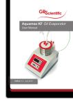
4. Panel Indication
SV8 DIGITAL METER
AL1 Alarm Indicate Light
AL1
AL2 Alarm Indicate Light
AL2
PV Display Window
Parameter Display Window (Unit Code)
SET Function Key
Menu Modify Key (SHIFT)
Increase Key
Decrease Key
KKSV8WE01-A/0-2
5. Operation Sequence
▲
▲
▲
1. SET Key: Under measuring status, short press SET key to enter into primary setting menu, long time press SET key can enter into
advanced setting menu (press SET key again -long time pressing-can return back to measuring status), SET key should be pressed
after each parameter be modified.
2. (SHIFT) key: Under measuring status, short time press
key, PV window will show Unit, then press ▲ key to choose the display
unit : M, cm, mm, kg, g, mg, Mpa, pa, ba, Mba, n, W, KW, RPM, Hz, KHz, mV, V, KV, mA, KA、Ω、KΩ、℃、F. When the input
signal is TC, Unit just can be choosed from ℃ and F, when modify the menu, short press key can let the value which need be modified
flash from right to left, when the value flash, press ▲ key and key can make change on the value.
3. ▲ /
Key: Press ▲ key the value will increase, press key the value will decrease.
4. If there is no operation for some time, the meter will return back to the measuring status automatically.
▲
▲
▲
6. Operation
SET
→
Power On
Input Signal Type
→
→
Alarm 1 Hysteresis
Unit Setting
Decimal Point Display
(TC/RTD input is useless)
→
→
Lowest Limit of Input Signal
SET
Alarm 1 Model
→
Highest Limit of Input Signal
→
SET
SET
Alarm 2
Filtering Value
→
→
SET
SET
Alarm 2 Hysteresis
Alarm 2 Model
PV Modify Value
SET
Display HIghest limit of Analog
→
→
SET
Display Lowest limit of Analog
→
→
SET
SET
→
Baud Rate
SET
LOCK
→
SET
Address
→
→
SET
SET
SET
SET
Alarm 1
SET
→
→
→
SET
Measuring
Status
Long time press SET
→
→
SHIFT
SET
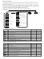
7. Primary Menu Setting
Parameter Name
Illustration
Setting Range
EX-Factory Setting
FL - FH
200
0 - FH
1
1-2
1
FL - FH
600
0 - FH
5
1-2
2
-1999-9999
0
0-9999
0
Setting Range
EX-Factory Setting
Input Signal Type
Reference Table
K
Input Signal Display Low Limit
Reference Table
-50
Input Signal Display High Limit
Reference Table
1200
0-3
0
0-255
255
Display Value for the Analog Low Limit
FL - FH
-50
Display Value for the Analog High Limit
FL - FH
1200
4800、9600
9600
1-255
1
#1 Alarm Setting Value
#1 Alarm Hysteresis Value
# 1 Alarm Mode: 1: Absoult Lowest Limit Alarm; 2: Absoult Highest Limit Alarm
#2 Alarm Setting Value
#2 Alarm Hysteresis Value
# 2 Alarm Mode: 1: Absoult Lowest Limit Alarm; 2: Absoult Highest Limit Alarm
PV Measuring Value Modify
LOCK Key: LCK=0001, only modify alarm value;
LCK=0010, all the parameters can not be changed (except LCK menu)
8. High Advanced Menu Setting
Parameter Name
Illustration
Decimal Point Setting (display only for Voltage, Ampere and Resistance signal input)
Filtering Value. The larger for the vlaue, the slower for the change on the Meter; The smaller
for the value, the quicker for the change on the Meter
RS485 Communication Baud Rate
RS485 Communication Meter Address
KKSV8WE01-A/0-3
Alarm Function Table
Alarm No
Alarm Type
1
Alarm Output (AL1, AL2 mutual independence)
HY
Absoult Low Limit Alarm
2
AL
Temperature Decrease
HY
Absoult High Limit Alarm
AL
Temperature Increase
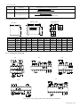
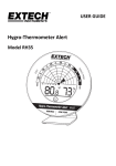
9. Dimension and Installation
Mounting Size
Side Face Size
Face Size
A
D
G +0.5
-0
C
E
H
J +0.5
-0
B
A
Size
K
F
H(Min)
J
K(Min)
45.5
25
45.5
25
89.5
45
25
90
25
67
67.5
25
67.5
25
94.5
44.5
90
25
45
25
94.5
91.5
92
25
92
25
13
83
75.5
155.5
30
76
30
13
83
155
76
30
155.5
30
C
D
E
F
48
97.5
3
94.5
45
96
97.5
3
94.5
72
97.5
3
94.5
96
48
97.5
3
96
96
97.5
3
160
80
96
80
160
96
4:(48*48)
48
6:(96*48)
48
7:(72*72)
72
8:(48*96)
9:(96*96)
80:(80*160)
16:(160*80)
B
G
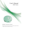
10. Connection Drawing
SV4
SV7
SV6
SV8
SV9
Note: If there is any change, please refer to the drawing on the Meter!
KKSV8WE01-A/0-4
11. Simple Problem Shooting
Shooting Method
Dispaly Message
Display HHHH
Input disconnect or over upper limit, please check input signal,FH value and ambient working temperature
Display LLLL
Input disconnect or under lower limit, please check input signal,FH value and ambient working temperature
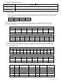
12. Communication
SV series Sensor Meter following Modbus RTU communication protocol, and it can run RS485 half-duplex communication.Read
function code is 0x03, write function code is 0x10, 16-bit CRC checking is applied. The coulometer can not return error message.
Data Frame flag:
Start bit
Data bit
Stop bit
Check bit
1
8
2
None
1. Read Multiple Registers
For example: The host computer read the float number AL1 (The value of Alarm 1 is 14.5).The address code of AL1 is 0x0000,
for AL1 is float number (4bits), it will occupy 2 data register. Reference IEEE-754 standard the hexadecimal 16 result of the
decimal float number is 0x66667641.
Request from the host computer (Read Multiple Registers)
1
2
3
4
Unit Address
Function Code
Start
Address Hi
Start
Address Lo
0x01
0x03
0x00
6
5
Data
Length Lo
Data
Length Hi
0x00
0x00
8
7
CRC Code Lo CRC Code Hi
0x04
0x44
0x09
Correct answer from slave unit (Read Multiple Registers)
1
2
3
Unit Address
Function
Code
Data Byte No.
0x01
0x03
0x04
Data 1
High byte
6
7
Data 1
Low byte
Data 2
High byte
Data 2
Low byte
0x66
0x66
CRC Code Lo CRC Code Hi
0xF4
0x41
0x76
9
8
5
4
0xE2
2. Write Multiple Registers
For example: The host computer read the float number AL1 (The value of Alarm 1 is 60).The address code of AL1 is 0x0000,
for AL1 is float number (4bits), it will occupy 2 data register. Reference IEEE-754 standard the hexadecimal 16 result of the
decimal float number is 0x66667641.
Request from the host computer (Read Multiple Registers)
3
2
1
Function
Unit
Address Code
0x01
0x10
4
Start
Address Hi
5
Start
Data
Address Lo Length Hi
0x00
0x00
0x00
6
Data
Length Lo
9
8
7
10
11
12
13
Data
Data 1
Data 1
CRC
Data 2
Data 2
CRC
Byte No. High byte Low byte High byte Low byte Code Lo Code Hi
0x02
0x04
0x16
0x00
0x00
0x44
0xFD
0xFC
Correct answer from slave unit (Write Multiple Registers)
1
Unit Address
0x01
2
3
4
5
6
Function Code
Start
Address Hi
Start
Address Lo
Data
Length Hi
Data
Length Lo
0x00
0x00
0x00
0x02
0x10
8
7
CRC Code Lo CRC Code Hi
0xC8
0x41
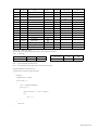
SV Series Meter Address Reference Table
No.
Address
0
0x0000
1
0x0001
2
0x0002
3
0x0003
4
0x0004
5
0x0005
Name
# 1 Alarm AL1
# 1 Alarm Hysteresis HY1
# 1 Alarm Type AD1
# 2 Alarm AL2
# 2 Alarm Hysteresis HY2
# 2 Alarm Type AD2
Type
Data
Number
Read / Write
float
4
R/W
float
4
R/W
float
4
R/W
float
4
R/W
float
4
R/W
4
R/W
float
Note
①
①
KKSV8WE01-A/0-5
No.
Address
6
0x0009
Type
Name
Data
Number
Read / Write
Modify Value PS
float
4
R/W
4
R/W
7
0x000A
Input Signal Type INP
float
8
0x000B
Display Up Limit FH
float
4
R/W
9
0x000C
Display Low Limit FL
float
4
R/W
10
0x000D
Decimal Point DP
float
4
R/W
11
0x000E
Filtering Setting Value
float
4
R/W
12
0x000F
Analog Low Limit Value BRL
float
4
R/W
13
0x0010
Analog High Limit Value BRH
float
4
R/W
14
0x0012
Unit Setting
float
4
R/W
15
0x0013
Baud Rate BUAD
float
4
R/W
16
0x0014
Address ADDR
float
4
R/W
Note
②
③
17
0x0015
Lock Setting
float
4
R/W
18
0x0016
Menu Shield
float
4
R/W
19
0x0032
Measuring Value
float
4
R
20
0x0033
# 1 Alarm Status
float
4
R
①
21
0x0034
# 2 Alarm Status
float
4
R
①
R: Read Only R/W: Read / Write
For Each Parameter’s Setting Range, Please Refer to The Operation User Manuel
Note ① Alarm Mode
Alarm Type
Low Limit Alarm High Limit Alarm
Reference
1
2
Alarm Status
Reference
ON
OFF
1
0
Note ② : Input Signal (Input parameter meter)
Note ③ : Code and Value reference table (refer to unit code reference table)
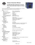
Acquiring Schedule of 16 units CRC code
unsigned int Get_CRC(uchar *pBuf, uchar num)
{
unsigned i,j;
unsigned int wCrc = 0xFFFF;
for(i=0; i<num; i++)
{
wCrc ^= (unsigned int)(pBuf[i]);
for(j=0; j<8; j++)
{
if(wCrc & 1){wCrc >>= 1; wCrc ^= 0xA001; }
else
wCrc >>= 1;
}
}
return wCrc;
}
KKSV8WE01-A/0-6