1
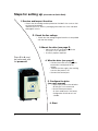
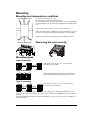
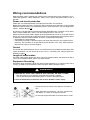
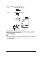
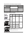
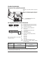
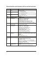
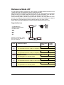
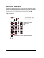
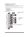
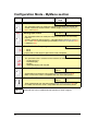
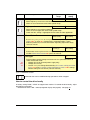
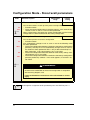
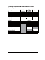
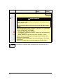
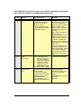
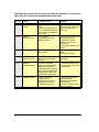
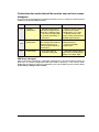
BLEMO
®
Frequenzumrichter
BASE-LINE
Variable speed drives for asynchonous motors
Frequency inverter ER12
Simplified manual
03/2009
BLEMO Frequenzumrichter
Siemensstraße 4
D-63110 Rodgau-Dudenhofen
Tel.: 06106/8295-0
Fax: 06106/8295-20
[email protected]
www.blemo.com
Contents
Important information _____________________________________________ 4
Before you begin _________________________________________________ 5
Steps for setting up _________________________________________________7
Mounting _______________________________________________________ 8
Wiring recommendations __________________________________________ 9
Power terminals _________________________________________________ 12
Control terminals ________________________________________________ 16
Electromagnetic compatibility (EMC)________________________________ 18
Check list ______________________________________________________ 21
Factory Configuration ____________________________________________ 22
Programming ___________________________________________________ 23
Reference Mode rEF _____________________________________________ 24
Monitoring mode MOn ___________________________________________ 25
Configuration mode ConF ________________________________________ 28
Migration ER11 - ER12___________________________________________ 34
Diagnostic and Troubleshooting ___________________________________ 36
3
Important information
NOTICE
Read these instructions carefully, and look at the equipment to become familiar with the device
before trying to install, operate, or maintain it. The following special messages may appear
throughout this documentation or on the equipment to warn of potential hazards or to call
attention to information that clarifies or simplifies a procedure.
The addition of this symbol to a Danger or Warning safety label indicates that an
electrical hazard exists, which will result in personal injury if the instructions are not
followed.
This is the safety alert symbol. It is used to alert you to potential personal injury
hazards. Obey all safety messages that follow this symbol to avoid possible injury
or death.
DANGER
DANGER indicates an imminently hazardous situation, which, if not avoided, will result in
death or serious injury.
WARNING
Warning indicates a potentially hazardous situation, which, if not avoided, can result in
death or serious injury.
CAUTION
CAUTION indicates a potentially hazardous situation, which, if not avoided, can result in
minor or moderate injury.
CAUTION
CAUTION, used without the safety alert symbol, indicates a potentially hazardous
situation which, if not avoided, can result in property damage.
PLEASE NOTE
The word "drive" as used in this manual refers to the controller portion of the adjustable speed
drive as defined by NEC.
Electrical equipment should be installed, operated, serviced, and maintained only by
qualified personnel. No responsibility is assumed by BLEMO for any consequences
arising out of the use of this material.
© 2009 BLEMO All Rights Reserved
4
Before you begin
Read and understand these instructions before performing any procedure with this drive.
DANGER
HAZARD OF ELECTRIC SHOCK, EXPLOSION, OR ARC FLASH
• Read and understand this manual before installing or operating the ER12 drive.
Installation, adjustment, repair, and maintenance must be performed by qualified
personnel.
• The user is responsible for compliance with all international and national electrical code
requirements with respect to grounding of all equipment.
• Many parts of this drive, including the printed circuit boards, operate at the line voltage.
DO NOT TOUCH. Use only electrically insulated tools.
• DO NOT touch unshielded components or terminal strip screw connections with voltage
present.
• DO NOT short across terminals PA/+ and PC/– or across the DC bus capacitors.
• Before servicing the drive:
- Disconnect all power, including external control power that may be present.
- Place a “DO NOT TURN ON” label on all power disconnects.
- Lock all power disconnects in the open position.
- WAIT 15 MINUTES to allow the DC bus capacitors to discharge. Then follow the
“Bus Voltage Measurement Procedure” in the user manual to verify that the DC
voltage is less than 42 V. The drive LEDs are not indicators of the absence of DC bus
voltage.
• Install and close all covers before applying power or starting and stopping the drive.
Failure to follow these instructions will result in death or serious injury.
DANGER
UNINTENDED EQUIPMENT OPERATION
• Read and understand this manual before installing or operating the ER12 drive.
• Any changes made to the parameter settings must be performed by qualified
personnel.
Failure to follow these instructions will result in death or serious injury.
5
WARNING
DAMAGED DRIVE EQUIPMENT
Do not operate or install any drive or drive accessory that appears damaged.
Failure to follow these instructions can result in death, serious injury, or
equipment damage.
WARNING
LOSS OF CONTROL
• The designer of any control scheme must consider the potential failure modes of control
paths and, for certain critical control functions, provide a means to achieve a safe state
during and after a path failure. Examples of critical control functions are emergency stop
and overtravel stop.
• Separate or redundant control paths must be provided for critical control functions.
• System control paths may includ+e communication links. Consideration must be given
to the implications of unanticipated transmission delays or failures of the link. a
Failure to follow these instructions can result in death, serious injury, or
equipment damage.
a. For additional information, refer to NEMA ICS 1.1 (latest edition), “Safety Guidelines for the
Application, Installation, and Maintenance of Solid State Control”
and to NEMA ICS 7.1 (latest edition), “Safety Standards for Construction and Guide for
Selection, Installation and Operation of Adjustable-Speed Drive Systems.”
6
Steps for setting up (also refer to Quick Start)
1. Receive and inspect the drive
• Check that the catalog number printed on the label is the same as that
on the purchase order.
• Remove the ER12 from its packaging and check that it has not been
damaged in transit.
2. Check the line voltage
• Check that the voltage range of the drive is compatible
with the line voltage.
3. Mount the drive (see page 5)
• Mount the drive in accordance with the
instructions in this document.
• Install any options required.
Steps 2 to 4 must
be performed with
the power off.
4. Wire the drive (see page 8)
• Connect the motor, ensuring that its
connections correspond to the
voltage.
• Connect the line supply, after making
sure that the power is off.
• Connect the control part.
5. Configure the drive
(see user manual)
• Apply input power to the drive but
do not give a run command.
• Set the motor parameters
(in Conf mode) only if the factory
configuration of the drive is not
suitable.
6. Start
7
Mounting
Mounting and temperature conditions
≥ 50 mm
(1.97 in)
Install the unit vertically, at ± 10˚.
Do not place it close to heating elements.
Leave sufficient free space to ensure that the air required for
cooling purposes can circulate from the bottom to the top of the
unit.
≥d
≥d
Free space in front of unit: 10 mm (0.39 in.) minimum.
≥ 50 mm
(1.97 in)
When IP20 protection is adequate, we recommend that the vent
cover(s) on the top of the drive be removed, as shown below.
We recommend to install the drive on a dissipative surface.
Removing the vent cover(s)
Mounting types
Type A mounting
Free space ≥ 50 mm (≥ 1.97 in.) on each side,
with vent cover(s) fitted.
Type B mounting
Drives mounted side by side, with vent cover(s) removed (the degree of protection becomes IP20).
Type C mounting
Free space ≥ 50 mm (≥ 1.97 in.) on each side,
with vent cover(s) removed.
With these types of mounting, the drive can be used up to an ambient temperature of 50˚C
(122˚F), with a switching frequency of 4 kHz. Fanless references need derating, consult the user
manual.
For other temperature and other switching frequencies, consult the user manual available on
www.blemo.com.
8
Wiring recommendations
Keep the power cables separate from control circuits with low-level signals (detectors, PLCs,
measuring apparatus, video, telephone). Always cross control and power cables at 90˚ if
possible.
Power and circuit protection
Follow wire size recommendations according to local codes and standards.
Before wiring power terminals, connect the ground terminal to the grounding screws located
below the output terminals (see subheading «Access to the terminals if you use stripped wire
cables», indicator B page 12).
The drive must be grounded in accordance with the applicable safety standards. ER12 drives
have an internal EMC filter, and as such the leakage current is over 3.5 mA.
Where local and national codes require upstream protection by means of a residual current
device, use a type A device for single-phase drives and a type B device for three-phase drives
as defined in the IEC Standard 60755. Choose a suitable model integrating:
• High frequency current filtering
• A time delay that helps to prevent tripping caused by the load from stray capacitance on
power-up. The time delay is not possible for 30 mA devices; in this case, choose devices
with immunity against nuisance tripping
Control
For control and speed reference circuits, we recommend using shielded twisted cables with
a pitch of between 25 and 50 mm (0.98 and 1.97 in.), connecting the shield to ground as
outlined on page 6.
Length of motor cables
For motor cable lengths longer than 50 m (164 ft) for shielded cables and longer than 100 m
(328 ft) for unshielded cables, please use motor chokes.
Equipment Grounding
Ground the drive according to local and national code requirements. A minimum wire size of
10 mm∑ (6 AWG) may be required to meet standards limiting leakage current.
DANGER
HAZARD OF ELECTRIC SHOCK, EXPLOSION, OR ARC FLASH
• The drive panel must be properly grounded before power is applied.
• Use the provided ground connecting point as shown in the figure below.
Failure to follow these instructions will result in death or serious injury.
• Ensure that the resistance of the ground is one ohm or
less.
• When grounding several drives, you must connect each
one directly, as shown in the figure to the left.
• Do not loop the ground cables or connect them in series.
9
WARNING
RISK OF DRIVE DESTRUCTION
• The drive will be damaged if input line voltage is applied to the output terminals
(U/T1,V/T2,W/T3).
• Check the power connections before energizing the drive.
• If replacing another drive, verify that all wiring connections to the drive comply with
wiring instructions in this manual.
Failure to follow these instructions can result in death, serious injury, or
equipment damage.
WARNING
INADEQUATE OVERCURRENT PROTECTION
• Overcurrent protective devices must be properly coordinated.
• The Canadian Electrical Code and the National Electrical Code require branch circuit
protection. Use the fuses recommended in the user manual.
• Do not connect the drive to a power feeder whose short-circuit capacity exceeds the
drive short-circuit current rating indicated within the in user manual.
Failure to follow these instructions can result in death, serious injury, or
equipment damage.
10
Wiring diagram for factory settings
ER12
Single-phase supply 200...240 V
ER12
3-phase supply 200...240 V (1)
a
(3)
c
AO1
AI1
COM
b
+5V
R1C
R1B
T/L3
S/L2
R/L1
R1A
R/L1
S/L2/N
N
Single-phase supply 100...120 V
R/L1
ER12
PA
(4)
(5)
PB
+24 V
LI4
LI3
LI2
LI1
COM
CLO
LO1
W/T3
W1
V/T2
V1
U/T1
U1
PA / +
PC / -
+
-
(2)
M
3a
3-phase
motor
Source
(1) R1 relay contacts, for remote indication of the drive status.
(2) Internal + 24 VDC. If an external source is used (+ 30 VDC maximum), connect the 0 V
of the source to the COM terminal, and do not use the + 24 VDC terminal on the drive.
(3) Reference potentiometer (maximum 10 kΩ).
(4) Optional braking module
(5) Optional braking resistor.
Note:
• Use transient voltage surge suppressors for all inductive circuits near the drive or coupled
to the same circuit (relays, contactors, solenoid valves, etc).
• The ground terminal (green screw) is located at the opposite location it was on the ER11,
(see wiring trap label).
11
Power terminals
Line supply is at the top of the drive, the motor power supply is at the bottom of the drive. The
power terminals can be accessed without opening the wiring trap if you use stripped wire
cables.
Access to the power terminals
Access to the terminals if you use stripped wire cables
B) Grounding screws located below the output terminals.
DANGER
HAZARD OF ELECTRIC SHOCK, EXPLOSION, OR ARC FLASH
Replace the wiring trap before applying power.
Failure to follow these instructions will result in death or serious injury.
CAUTION
RISK OF BODILY INJURY
Use pliers to remove the break-away tabs of the wiring trap.
Failure to follow these instructions can result in injury.
12
Access to the line supply terminals to connect ring terminals
Wiring trap
A) IT jumper on ER12
13
Power terminals
Access to the motor power terminals if you use ring terminals
14
Characteristics and functions of power terminals
Terminals
R/L1 - S/L2/N
R/L1 - S/L2/N
R/L1 - S/L2 - T/L3
PA/+
PC/PO
U/T1 - V/T2 - W/T3
Function
ER12
Ground terminal
Power supply
All ratings
1-phase 100…120 V
1-phase 200…240 V
3-phase 200…240 V
All ratings
+ output (dc) to the braking module
dc Bus (divisible part on wiring trap)
- output (dc) to the braking module
dc Bus (divisible part on wiring trap)
Not used
Outputs to the motor
All ratings
All ratings
Arrangement of power terminals
Size 1
Applicable
wire size (1)
Recommended
wire size (2)
Tightening
torque (3)
mm2 (AWG)
mm2 (AWG)
N·m (lb.in)
Size 1
0.18KU
0.37KU
0.18K
0.37K
0.55K
0.75K
0.18/3K
0.37/3K
0.75/3K
2 to 3.5
(14 to 12)
2
(14)
0.8 to 1
(7.1 to 8.9)
Size 2C
0.75KU
1.5K
2.2K
3.5 to 5.5
(12 to 10)
5.5
(10)
Size 2F
1.5/3K
2.2/3K
2 to 5.5
(14 to 10)
2 (14) for U15M3
3.5 (12) for U22M3
Size 3
3.0/3K
4.0/3K
5.5 (10)
5.5 (10)
ER12
Size 2
Size 3
1.2 to 1.4
( 10.6 to 12.4)
(1) The value in bold corresponds to the minimum wire gauge
to guarantee secureness.
(2) 75˚C (167 ˚F) copper cable (minimum wire size for rated
use).
(3) Recommended to maximum value.
15
Control terminals
Access to the control terminals
To access the control terminals, open the
cover.
Note: For information regarding HMI button
functions, see "HMI description" on page 23.
It is possible to lock the cover
with a lead seal.
Arrangement of the control terminals
Normally close (NC) contact of the relay
R1C
Common pin of the relay
COM
Common of analog and logic I/Os
AI1
Analog input
5V
+5V supply provided by the drive
AO1
Analog output
LO1
Logic output (collector)
CLO
Common of the logic output (emitter)
LI1
Logic input
LI2
Logic input
Nota: To connect cables, use a slotted LI3
screwdriver 0,6x3,5.
LI4
Logic input
LO1
CLO
COM
LI1
LI2
LI3
LI4
+24V
COM
AI1
5V
AO1
Normally open (NO) contact of the relay
R1B
R1A
R1B
R1C
R1A
RJ45
Logic input
+24V +24 V supply provided by the drive
RJ45
Connection for software, Modbus network
or remote display.
ER12 Control
terminals
Applicable wire size (1)
Tightening torque (2)
mm2 (AWG)
N·m (lb.in)
R1A, R1B, R1C
0.75 to 1.5 (18 to 16)
Other terminals
0.14 to 1.5 (26 to 16)
0.5 to 0.6 (4.4 to 5.3)
(1) The value in bold corresponds to the minimum wire guage to guarantee secureness.
(2) Recommended to maximum value.
16
Characteristics and functions of the control terminals
Terminal
R1A
Function
NO contact of the
relay
R1B
NC contact of the
relay
R1C
Common pin of the
relay
COM
AI1
Common of analog and logic I/Os
Voltage or current
• resolution: 10 bits
analog input
• precision: ± 1 % at 25˚C (77˚F)
• linearity: ± 0.3% (of full scale)
• sampling time: 20 ms ± 1 ms
Analog voltage input 0 to +5 V or 0 to +10 V
(maximum voltage 30 V) impedance: 30 kΩ
Analog current input x to y mA, impedance: 250 Ω
Power supply for
• precision: ± 5%
potentiometer
• maximum current: 10 mA
Voltage or current
• resolution: 8 bits
analog output
• precision: ± 1 % at 25˚C (77˚F)
• linearity: ± 0.3 % (of full scale)
• refresh time: 4 ms (maximum 7 ms)
Analog voltage output: 0 to +10 V
(maximum voltage +1%)
• minimum output impedance: 470 Ω
Analog current output: x to 20 mA
• maximum output impedance: 800 Ω
Logic output
• voltage: 24 V (maximum 30 V)
(collector)
• impedance: 1 kΩ, maximum 10 mA (100 mA in open
collector)
• linearity: ± 1%
• refresh time: 20 ms ± 1 ms
Common of the logic output (emitter)
Logic inputs
Programmable logic inputs
• +24 V power supply (maximum 30 V)
• impedance: 3.5 kΩ
• state: 0 if < 5 V, state 1 if > 11 V in positive logic
• state: 1 if < 10 V, state 0 if > 16 V or switched off (not
connected) in negative logic
• sampling time: < 20 ms ± 1 ms.
+ 24 V supply
+ 24 V -15% +20% protected against short-circuits and
provided by the
overloads.
drive
Maximum customer current available 100 mA
5V
AO1
LO1
CLO
LI1
LI2
LI3
LI4
+24V
17
Electrical characteristics
Minimum switching capacity:
• 5 mA for 24 VDC
Max. switching capacity:
• 2 A for 250 VAC and for 30 VDC on inductive load
(cos ϕ = 0.4 and L/R = 7 ms)
• 3 A for 250 VAC and 4 A for 30 VDC on resistive load
(cos ϕ = 1 and L/R = 0)
• response time: 30 ms max.
Electromagnetic compatibility (EMC)
IMPORTANT: The high frequency equipotential ground connection between the drive, motor,
and cable shielding does not eliminate the need to connect the ground (PE) conductors
(green-yellow) to the appropriate terminals on each unit. See Wiring recommendations
page 9.
Principle of precautions
• Grounds between the drive, motor, and cable shielding must have high frequency
equipotentiality.
• When using shielded cable for the motor, use a 4-conductor cable so that one wire will be
the ground connection between the motor and the drive. Size of the ground conductor
must be selected in compliance with local and national codes. The shield can then be
grounded at both ends. Metal ducting or conduit can be used for part or all of the shielding
length, provided there is no break in continuity.
• When using shielded cable for Dynamic Brake (DB) resistors, use a 3-conductor cable so
that one wire will be the ground connection between the DB resistor assembly and the
drive. The size of the ground conductor must be selected in compliance with local and
national codes. The shield can then be grounded at both ends. Metal ducting or conduit
can be used for part or all of the shielding length, provided there is no break in continuity.
• When using shielded cable for control signals, if the cable is connecting equipment that is
close together and the grounds are bonded together, then both ends of the shield can be
grounded. If the cable is connected to equipment that may have a different ground
potential, then ground the shield at one end only to prevent large currents from flowing in
the shield. The shield on the ungrounded end may be tied to ground with a capacitor (for
example: 10 nF, 100 V or higher) in order to provide a path for the higher frequency noise.
Keep the control circuits away from the power circuits. For control and speed reference
circuits, we recommend using shielded twisted cables with a pitch of between 25 and 50
mm (0.98 and 1.97 in.)
• Ensure maximum separation between the power supply cable (line supply) and the motor
cable.
• The motor cables must be at least 0.5 m (20 in.) long.
• Do not use surge arresters or power factor correction capacitors on the variable speed
drive output.
• For installation of the optional EMC plate and instructions for meeting IEC 61800-3
standard, refer to the section entitled “Installing the EMC plates” and the instructions
provided with the EMC plates.
18
DANGER
HAZARD OF ELECTRIC SHOCK, EXPLOSION, OR ARC FLASH
• Do not expose cable shielding except where connected to ground at the metal cable
glands and underneath the grounding clamps.
• Ensure that there is no risk of the shielding coming into contact with live components
Failure to follow these instructions will result in death or serious injury.
Installation diagram (example)
1 Non-shielded wires for the output of the status
relay contacts.
2 Sheet steel grounded casing not supplied with
the drive (see user manual), to be fitted as
indicated on the diagram.
3 PA & PC terminals, to the braking module
DC Bus
4 Shielded cable for connecting the control/
signalling wiring.
For applications requiring several conductors,
use small cross-sections (0.5 mm2, 20 AWG).
The shielding must be connected to ground at
both ends. The shielding must be continuous
and intermediate terminals must be in EMC
shielded metal boxes.
5 Shielded cable for motor connection with
shielding connected to ground at both ends.
This shielding must be continuous, and if there
are any intermediate terminals, these must be
in an EMC shielded metal box. The motor
cable PE grounding conductor (green-yellow)
must be connected to the grounded casing.
6 Grounding conductor, cross-section 10 mm2
(6 AWG) according to IEC 61800-5-1 standard.
7 Power input (non shielded cable)
Attach and ground the shielding of control and motor cables as close as possible to the drive:
- expose the shielding
- use cable clamps of an appropriate size on the parts from which the shielding has been
exposed, to attach them to the casing.
The shielding must be clamped tightly enough to the metal plate to ensure correct
contact.
- types of clamp: stainless steel (delivered with the optional EMC plate).
19
EMC conditions for ER12
C1 EMC category is reached if length of shielded cable is 5 meter (16.4 ft) maximum and
Switching frequency SFr is 4, 8 or 12 kHz.
C2 EMC category is reached if length of shielded cable is 10 meter (32.8 ft) maximum and
Switching frequency SFr is 4, 8 or 12 kHz and if length of shielded cable is 5 meter (16.4 ft)
maximum for all other values of Switching frequency SFr.
Internal EMC filter on ER12
All ER12 drives have an built-in EMC filter. As a result they exhibit leakage current to ground.
If the leakage current creates compatibility problems with your installation (residual current
device or other), then you can reduce the leakage current by opening the IT jumper (see
chapter Access to the line supply terminals to connect ring terminals, indicator A page 13). In
this configuration EMC compliance is not guaranteed.
CAUTION
DRIVE LIFETIME REDUCTION
On ER12 ratings, if the filters are disconnected, the drive’s switching frequency must not
exceed 4 kHz. Refer to Switching Frequency parameter SFr (see user manual for
adjustment).
Failure to follow these instructions can result in equipment damage.
20
Check list
Read carefully the safety information in the user manual, and the simplified manual. Before
starting up the drive, please check the following points regarding mechanical and electrical
installations, then use and run the drive.
For complete documentation, refer to www.blemo.com.
1. Mechanical installation
• For drive mounting types and recommendations on the ambient temperature, please see
the Mounting instructions on page 8 of the simplified manual and in the user manual.
• Mount the drive vertically as specified, see Mounting instructions on page 8 of the
simplified manual or in the user manual.
• The use of the drive must be in agreement with the environments defined by the standard
60721-3-3.
• Mount the options required for your application, see catalogue.
2. Electrical installation
• Connect the drive to the ground, see Equipment Grounding on page 9 of the simplified
manual and in the user manual.
• Ensure that the input power voltage corresponds to the drive nominal voltage and connect
the line supply as shown on the drawing Wiring diagram for factory settings on page 11 of
the simplified manual and in the user manual.
• Ensure that appropriate input power fuses and circuit breaker are installed according to
the catalogue.
• Wire the control terminals as required, see Control terminals on page 13 of the simplified
manual and in the user manual. Separate the power cable and the control cable according
to EMC compatibility rules.
• The range ER12 integrates EMC filter. The leakage current can be reduced using the IT
jumper as explained in the paragraph Internal EMC filter on ER12 on page 20 of the
simplified manual and in the user manual.
• Ensure that motor connections correspond to the voltage (star, delta).
3. Use and run the drive
• Start the drive and you will see Standard motor frequency bFr at the first power on. Check
that the frequency defined by the frequency bFr (the factory setting is 50 Hz) is in
accordance with the frequency of the motor, see the paragraph First power-up on page 23
of the simplified manual and in the user manual.
• For the following power on, you will see rdY on the HMI.
• MyMenu (upper part of CONF mode) permits you to set the drive for most applications (see
page 29).
•
21
At any time, Factory / recall customer parameter set FCS function permits you to reset the
drive with factory settings (see page 31).
Factory Configuration
Drive factory setting
The ER12 is factory-set for the most common operating conditions (motor rating according to
drive rating):
• Display: drive ready (rdY) motor stopped or motor frequency reference while running.
• Standard motor frequency bFr: 50 Hz (see page 29).
• Rated motor voltage UnS: 230 V.
• Acceleration time ACC and Deceleration time dEC: 3 seconds
• Low speed LSP: 0 Hz
• High speed HSP: 50 Hz
• Motor control type Ctt: Std (U/F standard law)
• IR compensation (law U/F) UFr: 100%
• Motor thermal current Ith: equal to nominal motor current (value determined by the drive
rating)
• Automatic DC injection current SdC1: 0.7 x nominal motor current, for 0.5 seconds.
• Decel Ramp Adaptation assignement brA: YES (Automatic adaptation of the deceleration
ramp in the event of overvoltage on braking).
• No automatic restarting after a detected fault is cleared
• Switching frequency SFr: 4 kHz
• Logic inputs:
- LI1: forward (2-wire transitional control), start drive
- LI2, LI3, LI4: no assignment
• Logic output: LO1: no assignment
• Analog input: AI1 (0 to + 5 V) speed reference
• Relay R1: Default setting is fault. R1A opens and R1B closes when a fault is detected or
no line voltage is present.
• Analog output AO1: no assignment
If the above values are compatible with the application, the drive can be used without
changing the settings.
22
Programming
HMI description
Functions of the display and keys
• REFERENCE mode LED
• Value LED (2)
• 4"7-segment"
displays
• Unit LED (1)
• Charge LED
• MONITORING mode LED
CONFIGURATION mode LED
• MODE button
Switches between the
control/programming
modes. The MODE button is
only accessible with the HMI
door open.
• ESC button: Exits
a menu or
parameter, or
aborts the
displayed value to
return to the
previous value in
the memory.
• STOP button:
stops the motor
(could be hidden
by door if function
disabled).
See instructions
for "RUN/STOP"
cover removal.
• Jog dial
- Acts as a potentiometer in local mode.
- For navigation when turned clockwise or counterclockwise
- and selection / validation when pushed.
This action is represented by this symbol
• RUN button: Start
running if the
function is
configured (could
be hidden by door
if function
disabled).
(1) If illuminated, indicates that a unit is displayed, ex AMP displayed for "Amps"
(2) If illuminated, indicates that a value is displayed, ex 0.5 displayed for "0.5"
First power-up
At first power-up you are prompted to set Standard motor frequency bFr page 29. Next time
power is applied rdY appears. Operating mode selection is then possible using the MODE or
ENTER key as detailed below.
Menus structure
Menus and parameters are classified in three branches (modes): Reference rEF page 24,
Monitoring MOn page 25 and Configuration COnF page 28, described below. Switching
between these modes is possible at any time using the MODE key or Jog Dial. First MODE
key depression moves from current position to the top of the branch. Second depression
switches to next mode.
23
Reference Mode rEF
Use the reference mode to monitor and, if local control is enabled (Reference channel 1 Fr1
= AIU1) adjust the actual reference value by rotating the jog dial.
When local control is enabled, the jog dial of the HMI acts as a potentiometer to change the
reference value up and down within the limits preset by other parameters (LSP and HSP).
There is no need to press the ENT key to confirm the change of the reference.
If local command mode is disabled, using Command channel 1 Cd1, only reference values
and units are displayed. The value will be "read only" and cannot be modified by the jog dial
(the reference is no longer given by the jog dial but from an AI or other source).
Actual reference displayed depends on choice made by Reference channel 1 Fr1.
Organization tree
(1) Depending on
reference channel active.
Possible values:
LFr
AIU1
FrH
rPI
rPC
ESC
(1)
LFr
(1)
ENT
ESC
displayed parameter value
and unit of the diagram is
given as examples
Code
value
unit
rEF
ENT
51.
3
HErt
2 s or ESC
Name/Description
External reference value
Adjustment
range
Factory
setting
0 Hz to HSP
-
This parameter allows to modify the frequency reference with the jog dial.
AIU1
Analog input virtual
FrH
Speed reference
rPI
Internal PID reference
0 to 100 %
-
This parameter allows to modify the frequency reference with analog input.
0 Hz to HSP
-
0 to 100 %
-
This parameter is in read-only mode.
(1)
rPC
This parameter allows to modify the PID internal reference with the jog dial.
PID reference value
0 to 100 %
-
This parameter is in read-only mode.
(1) It is not necessary to press ENT key to validate the modification of the reference.
24
Monitoring mode MOn
This mode allows monitoring of application values. It is also possible to select the desired
parameter to be monitored. When the drive is running, the value of the parameter selected is
displayed. While the value of the desired new monitoring parameter is being displayed, press
a second time on the jog dial button to display the units.
The default value which is displayed is the motor Output frequency rFr page 26.
Changing the default value is achieved by pressing the jog dial more than 2 sec.
Organization tree
value
unit
displayed parameter values
and units of the diagram are
given as examples
ENT
(1)
2 s or ESC
HErt
HErt
2 s or ESC
HErt
2 s or ESC
(1) Depending on
reference channel active.
Possible values:
LFr
AIU1
2 s or ESC
2 s or ESC
2 s or ESC
2 s or ESC
2 s or ESC
MAICOd
25
see user manual for details on Maintenance MAI- menu
Code
LFr
Name
External reference value
Unit
Hz
Displays the speed reference coming from the remote keypad.
AIU1
Analog input virtual
%
Displays the speed reference coming from the jog dial.
FrH
Speed reference
rFr
Output frequency
Hz
This parameter is in read-only mode.
Hz
This parameter provides the estimated motor speed given in Hz (range -400
Hz to 400 Hz.
In Standard law Std, the Output frequency rFr is equal to the estimated
motor stator frequency.
In Performance law PErF, the Output frequency rFr is equal to the
estimated motor rotor frequency.
LCr
Motor current
A
Estimation of the effective motor current (output of the drive) with an
accuracy of 5%.
During DC injection, the current displayed is the maximum value of current
injected in the motor.
ULn
Main voltage
V
Line voltage from the point of view of the DC bus, motor running or stopped.
tHr
Motor thermal state
%
Display of the motor thermal state. Above 118%, the drive trips in Motor
overload OLF page 39.
tHd
Drive thermal state
%
Display of the drive thermal state. Above 118%, the drive trips in Drive
overheat OHF page 39.
Opr
Output power
%
The parameter shows the ratio between "estimated motor power (on the
shaft) versus Drive rating."
Range: 0 to 100% of drive rated power.
26
Code
StAt
rdY
rUn
ACC
dEC
dCb
CLI
nSt
Obr
CtL
tUn
FSt
nLP
MAI-
Name
Product status
This parameter displays the state of the drive and motor.
• Drive ready
• Drive running, the last digit on the right of the code indicate also direction
and speed.
• Acceleration, the last digit on the right of the code indicate also direction
and speed.
• Deceleration, the last digit on the right of the code indicate also direction
and speed.
• DC injection braking in progress
• Current limit, displayed code is blinking.
• Freewheel stop control
• Auto-adapted deceleration
• Controlled stop on mains phase loss
• Auto-tuning in progress
• Fast stop
• No line power. When control power is present and there is no power on the
main input and no run command present.
Maintenance menu
See user manual for details on Maintenance MAI- menu.
COd
HMI Password
Possible state value:
OFF: factory setting
ON: code activated
The protection enables only access to rEF (see page 24) and MOn (see page
25 modes, except using Software.
27
Configuration mode ConF
The Configuration mode includes 3 parts :
1 My menu includes 11 factory set parameters (among them 9 visible by default). Up to 25
parameters are available for user customization using software.
2 store/recall parameter set: these 2 functions allow to store and recall customer settings.
3 FULL: This menu permits to access to all other parameters. It includes 6 sub-menus:
- Input Output menu I-O-,
- Motor control menu drC-,
- Control menu Ctl-,
- Function menu FUn-,
- Fault detection management menu FLt-,
- Communication menu COM-.
Organization tree
ConF
(1)
1
displayed parameter values of
the diagram are given as
examples
value
unit
0
bFr
50
Fr1
AI1
ACC
3
dEC
3
LSP
0
HSp
50
nPr
3
nCr
6
AI1t
5U
2 s or ESC
2 s or ESC
2 s or ESC
2 s or ESC
2 s or ESC
2 s or ESC
2 s or ESC
2 s or ESC
HErt
HErt
SEC
SEC
HErt
(1) Depending on
reference channel active.
Possible values:
LFr
AIU1
HErt
HP
AMP
Plus 14 other customizable parameters
selectable (in "FULL" list) using software
2
SCS
nO
FCS
nO
3
28
Configuration Mode - MyMenu section
Code
LFr
Name/Description
External reference value
Adjustment
range
0 Hz to HSP
Factory setting
-
This parameter allows to modify the frequency reference with the jog dial.
Visible if reference channel active is remote display (Reference channel 1
Fr1 is set to LCC).
AIU1
Analog input virtual
0 to 100 %
-
This parameter allows to modify the frequency reference with the analog
input AI1.
Visible if reference channel active is integrated display (Reference channel 1
Fr1 is set to AIU1) or if local forcing is activated (Forced local assignment FLO
is different to nO).
Standard motor frequency
bFr
50
60
Fr1
AI1
LCC
Mdb
AIUI
ACC
50 Hz
• 50 Hz
• 60 Hz
Corresponds to the nominal speed of the motor nameplate.
Reference channel 1
AI1
This parameter allows selection of the reference channel.
• Analog input AI1
• Remote display
• Modbus
• Integrated display with Jog dial
Acceleration time
0.0 s to
999.9 s
3.0 s
Acceleration time between 0 Hz and the Rated motor frequency FrS.
Make sure that this value is compatible with the inertia being driven.
dEC
Deceleration time
0.0 s to
999.9 s
3.0 s
Time to decelerate from the Rated motor Rated motor frequency FrS to 0
Hz. Make sure that this value is compatible with the inertia being driven.
Parameter that can be modified during operation or when stopped.
29
Code
LSP
Name/Description
Low speed
Adjustment
range
0 Hz to HSP
Factory
setting
0 Hz
Motor frequency at minimum reference.
Allows to set a lower limit of the motor speed range.
HSP
High speed
LSP to tFr Hz
50 Hz
Motor frequency at maximum reference.
Allows to set an upper limit of the motor speed range.
Check that this setting is appropriate for the motor and the application.
nPr
Rated Motor Power
According to
drive rating
According to
drive rating
Rated motor power given on the nameplate. Visible only if Motor parameter
choice MPC is set to nPr. Performance is optimized within 1 rating
different (maximum). For more information regarding adjustment range,
see user manual.
nCr
Rated motor current
0.20 to
1.5 In (1)
According to
drive rating
Rated motor current given on the nameplate. Changing value of nCr
modifies Motor thermal currentIth (see user manual).
A11t
5U
10U
0A
AI1t type
5U
Drive hardware accept voltage and current AI. this parameter allows to
select the desired mode
• Voltage: 0 to 5 vdc (internal power supply only)
• Voltage: 0 to 10 vdc
• Current: x to y mA. Range determined by AI1 current scaling parameter
of 0% CrL1 and AI1 current scaling parameter of 100% CrH1 settings.
Default setting are 0 to 20 mA (see user manual).
(1) In = rated drive current
Parameter that can be modified during operation or when stopped.
How to control the drive locally
In factory setting "RUN", "STOP" and jog dial are inactive. To control the drive locally, adjust
the following parameter:
• Reference channel 1 Fr1 = AIU1 (Integrated display with jog dial). See page 29.
30
Configuration Mode - Store/recall parameters
Code
SCS
nO
Str1
2s
FCS
nO
rEC1
InI
InI1
2s
Name/Description
Adjustment
range
Store customer parameter set
Factory
setting
nO
This function creates a back up of the present configuration :
• Function inactive
• Saves the current configuration in the drive memory. SCS automatically
switches to nO as soon as save has been performed.
When a drive leaves the factory the current configuration and the backup
configuration are both initialized with the factory configuration.
Factory / recall customer parameter set
nO
This function permits to restore a configuration.
• Function inactive.
FCS automatically changes to nO as soon as one of the following action
has been performed.
• The current configuration becomes identical to the backup configuration
previously saved by SCS. FCS automatically changes to nO as soon as
this action has been performed. rEC1 is only visible if the backup has
been carried out. If this value appears, Ini1 is not visible.
• The current configuration becomes identical to the factory setting. If this
value appears, Ini1 is not visible.
• The current configuration becomes identical to the backup configuration
previously defined by software. If this value appears, Ini and reC1 are
not visible.
DANGER
UNINTENDED EQUIPMENT OPERATION
Check that the modification of the current configuration is compatible
with the wiring diagram used.
Failure to follow these instructions will result in death or serious
injury.
2s
31
To change the assignment of this parameter press the “ENT” key for 2 s.
Configuration Mode - Full menu (FULL)
Macro-configuration
Input / output or parameter
AI1
AIU1
AO1
LO1
R1
LI1 (2 wire)
LI2 (2 wire)
LI3 (2 wire)
LI4 (2 wire)
LI1 (3 wire)
LI2 (3 wire)
LI3 (3 wire)
LI4 (3 wire)
Fr1 (Reference channel 1)
Ctt (Motor control type)
rIn (Reverse inhibition)
SFS (PID start speed)
AI1t (AI1t type)
LFLl (4-20 mA loss behaviour)
SP2 (Preset speed 2)
SP3 (Preset speed 3)
SP4 (Preset speed 4)
MPC (Motor parameter choice)
AdC (Automatic DC injection)
Start / Stop
Ref. channel 1
No
No
No
No
PID
regulation
Speed
PID feedback
No
Reference channel 1
No
No
No drive detected fault
Forward
No
Reverse
Auto/Manu
2 preset speeds
4 preset speeds
Stop
Forward
No
Reverse
Auto / Manu
2 preset speeds
AIUI
AIUI
PUMP
YES
10.0
0A
YES
10.0
25.0
50.0
COS
YES
32
Code
Name/Description
Adjustment
range
Macro-configuration
CFG
2s
Factory
setting
Start/stop
DANGER
UNINTENDED EQUIPMENT OPERATION
Check that the selected macro configuration is compatible with the
wiring diagram used.
Failure to follow these instructions will result in death or serious
injury.
StS
PId
SPd
2s
33
Macro configuration provides a shortcut to configure a set of parameters
suited to a specific field of application.
3 macro configurations are available:
• Start/stop. Only forward is assigned
• PID regulation. Activate PID function, dedicate AI1 for feedback and
AIU1 for reference.
• Speed. Allocate LI to preset speed (same allocation as ER11)
provides a means of speeding up the configuration of functions for a
specific field of application.
Selecting a macro configuration assigns the parameters in this macro
configuration.
Each macro configuration can still be modified in the other menus.
To change the assignment of this parameter press the “ENT” key for 2 s.
Migration ER11 - ER12
The ER12 is compatible with ER11 (latest version), nevertheless some difference can exist
between both drives.
Both models (ER11 and ER12) are available in heatsink or base plate models.
Terminals
Power
• Before wiring power terminals, connect the ground terminal of the grounding screws
located below the output terminals to the protective ground (see indicator B page 12).
• The power connections are available without removing the power terminal cover.
Nevertheless, if necessary, it is possible to remove them using an adapted tool (IP20
protection requirement). Cover to be removed in case of using ring terminals (pressure
stress is 14 N for size 1 and 20 N for sizes 2 and 3).
• Pay attention to the input ground terminal located on right of the connector (was on left
on ER11). The ground connection is clearly indicated on input power terminal cover and
the screw colour is green.
Control
+15V
LI4
LI3
LI2
LI1
DO
+5V
AI1
0V
not used
RA
ER11
RC
Important: The control terminals are arranged and marked differently:
COM
AI1
5V
AO1
ER12
R1A
R1B
R1C
ATV11
LO1
CLO
COM
LI1
LI2
LI3
LI4
+24
ATV12
On ER11 «DO» is an analog output that can be configured as logic output. On ER12,
depending on your configuration, DO can be linked to LO1 or AO1.
The ER11 integrates an internal supply voltage of 15V, ER12 now integrates an internal
supply of 24V.
For information regarding mounting holes and dimensions, refer to user manual.
34
Settings
The information below explains the differences between the ER11 and ER12 to assist with
replacement. These information are convenient to assist for the management of drive
embedded HMI (RUN, STOP keypad and potentiometer).
• Replacing an ER11-…K
The embedded HMI of ER11 is not managing speed, as ER12 doesn’t (factory setting), there
is no modification to get equivalence.
LI2 to LI4 and AO1 are not assigned on ER12.
• Replacing an ER11-…KU
Main change is on the bFr and HSP settings. It is now 50 Hz as factory setting on ER12.
EMC filters are now integrated in ER12-...K
LI2 to LI4 and AO1 are not assigned on ER12.
• Replacing an ER11-…KA
EMC filters are now integrated in ER12.
LI2 to LI4 and AO1 are not assigned on ER12.
The active command channel is on terminals for ER12 (was front keypad on ER11-…KA).
To make embedded HMI active, it is necessary to set Reference channel 1 Fr1 = AIU1
(located in COnF menu). See page 29.
ER12 factory setting characteristics: see page 22.
More complete information is given in user manual (see www.blemo.com)
35
Diagnostic and Troubleshooting
Drive does not start, no error code displayed
• If the display does not light up, check the power supply to the drive (ground and input
phases connection, see page 12).
• The assignment of the "Fast stop" or "Freewheel" functions will prevent the drive starting
if the corresponding logic inputs are not powered up. The ER12 then displays nSt in
freewheel stop and FSt in fast stop. This is normal since these functions are active at zero
so that the drive will be stopped if there is a wire break. Assignment of LI to be checked in
COnF/FULL/FUn-/Stt- menu (see user manual).
• Make sure that the run command input(s) is activated in accordance with the selected
control mode (Type of control tCC and 2 wire type of control tCt parameters in COnF/
FULL/ I-O-menu).
• If the reference channel or command channel is assigned to a Modbus, when the power
supply is connected, the drive displays "nSt" freewheel and remain in stop mode until the
communication bus sends a command.
• In factory setting "RUN" and "STOP" button are inactive. Adjust Reference channel 1 Fr1
page 29 and Command channel 1 Cd1 parameters to control the drive locally (COnF/
FULL/CtL-menu). See chapter How to control the drive locally page 30.
Fault detection codes which cannot be reset automatically
The cause of the fault must be removed before resetting by cycling power to the drive.
SOF and tnF faults can also be reset remotely by means of a logic input (Detected fault reset
assignment rSF parameter in COnF/FULL/FLt-menu).
InFb, SOF and tnF codes can be inhibited and cleared remotely by means of a logic input
(Detected fault inhibition assignment InH parameter).
Code
Name
Possible causes
Remedy
CrF1
Precharge
• Charging relay not
operating properly or
charging resistor damaged
• Turn the drive off and then
back on again
• Check the connections
• Check the stability of the
main supply
• Contact local BLEMO
representative.
InFI
Unknown drive
rating
• The power card is
different from the card
stored
• Contact local BLEMO
representative.
InF2
Unknown or
incompatible
power board
• The power card is
incompatible with the control
card
• Contact local BLEMO
representative.
InF3
Internal serial
link
• Communication fault
between the internal cards
• Contact local BLEMO
representative.
36
Fault detection codes which cannot be reset automatically (continued)
37
Code
Name
Possible causes
Remedy
InF4
Invalid
industrialization
zone
• Internal data inconsistent
• Contact local BLEMO
representative.
InF9
Current
measurement
circuit failure
• Current measurement is
not correct due to
hardware circuit
• Contact local BLEMO
representative.
----
Problem with
application
Firmware
• Bad updated of the
application firmware with
the Multi-Loader
• Flash again the
application firmware of the
product
InFb
Internal thermal
sensor failure
• The drive temperature
sensor is not operating
correctly
• The drive is in short
circuit or open
• Contact local BLEMO
representative.
InFE
Internal CPU
• Internal microprocessor
fault
• Turn the drive off and
then back on again
• Contact local BLEMO
representative.
OCF
Overcurrent
• Parameters in the Motor
control menu drC- are not
correct
• Inertia or load too high
• Mechanical locking
• Check the parameters
• Check the size of the
motor/drive/load
• Check the state of the
mechanism
• Connect line motor
chokes
• Reduce the Switching
frequency SFr
• Check the ground
connection of drive, motor
cable and motor insolation.
SCFI
Motor short
circuit
SCF3
Ground short
circuit
• Short-circuit or grounding
at the drive output
• Ground fault during
running status
• Commutation of motors
during running status
• Significant current
leakage to ground if
several motors are
connected in parallel
• Check the cables
connecting the drive to the
motor, and the motor
insulation
• Connect motor chokes
SCF4
IGBT short
circuit
• Internal power
component short circuit
detected at power on
• Contact local BLEMO
representative.
Fault detection codes which cannot be reset automatically (continued)
Code
Name
Possible causes
Remedy
SOF
Overspeed
• Instability
• Overspeed link with the
inertia of the application
• Check the motor and
connected mechanical
equipment
• Overspeed is 10% more
than Maximum frequency
tFr so adjust this
parameter if necessary
• Add a braking resistor
• Check the size of the
motor/drive/load
• Check parameters of the
speed loop (gain and
stability)
tnF
Auto-tuning
• Motor not connected to
the drive
• One motor phase loss
• Special motor
• Motor is in rotation (by
load for example)
• Check that the motor/
drive are compatible
• Check that the motor is
present during auto-tuning
• If an output contactor is
being used, close it during
auto-tuning
• Check that the motor is
completly stopped
38
Fault detection codes that can be reset with the automatic restart function, after the cause has disappeared
These faults can also be reset by turning on and off or by means of a logic input (Detected
fault reset assignment rSF parameter).
OHF, OLF, OPF1, OPF2, OSF, SLF1, SLF2, SLF3 and tJF faults can be inhibited and cleared
remotely by means of a logic input (Detected fault inhibition management InH parameter).
Code
Name
Possible causes
Remedy
LFF1
AI current lost
fault
• Detection if:
• Analog input AI1 is
configured in current
• AI1 current scaling
parameter of 0% CrL1 is
greater than 3mA
• Analog input current is
lower than 2 mA
• Check the terminal
connection
ObF
Overbraking
• Braking too sudden or
driving load too high
• Increase the deceleration
time
• Install a module unit with a
braking resistor if necessary
• Check the main supply
voltage, to be sure that we
are under the maximum
acceptable (20% over
maximum main supply
during run status)
• Set automatic adaptation
of decel ramp brA to YES
OHF
Drive overheat
• Drive temperature too
high
• Check the motor load, the
drive ventilation and the
ambient temperature. Wait
for the drive to cool down
before restarting. See
Mounting and temperature
conditions page 8.
OLC
Process
overload
• Process overload
• Check the process and
the parameters of the drive
to be in phase
OLF
Motor overload
• Triggered by excessive
motor current
• Check the setting of the
motor thermal protection,
check the motor load.
OPF1
1 output phase
loss
• Loss of one phase at drive
output
• Check the connections
from the drive to the motor
• In case of using
downstream contactor,
check the right connection,
cable and contactor
39
Fault detection codes that can be reset with the automatic restart function, after the cause has disappeared (continued)
Code
Name
Possible causes
Remedy
OPF2
3 output phase
loss
• Motor not connected
• Motor power too low,
below 6% of the drive
nominal current
• Output contactor open
• Instantaneous instability
in the motor current
• Check the connections
from the drive to the motor
• Test on a low power
motor or without a motor:In
factory settings mode,
motor phase loss detection
is active Output phase loss
detection
OPL = YES. To check the
drive in a test or
maintenance environment,
without having to use a
motor with the same rating
as the drive, deactivate
motor phase loss detection
Output phase loss detection
OPL = nO
• Check and optimize the
following parameters: IR
compensation UFr, Rated
motor voltage UnS and
Rated motor current nCr
and perform Auto-tuning
tUn.
OSF
Main
overvoltage
• Line voltage too high:
- Only at power on of
the drive, supply is
10% over the maximal
voltage acceptable
- Power with no run
order, 20% over
maximal main supply
• Disturbed mains supply
• Check the line voltage
PHF
Input phase
loss
• Drive incorrectly supplied
or a fuse blown
• Failure of one phase
• 3-phase ER12 used on a
single-phase line supply
• Unbalanced load
• This protection only
operates with the drive on
load
• Check the power
connection and the fuses.
• Use a 3-phase line
supply.
• Disable the fault by Input
phase loss
IPL = nO.
40
Fault detection codes that can be reset with the automatic restart function, after the cause has disappeared (continued)
Code
Name
Possible causes
Remedy
SCF5
Motor short
circuit
• Short-circuit at drive
output
• Short circuit detection at
the run order or DC injection
order if parameter IGBT test
Strt = YES
• Check the cables
connecting the drive to the
motor, and the motor’s
insulation
SLF1
Modbus
communication
• Interruption in
communication on the
Modbus network
• Check the connections of
communication bus.
• Check the time-out
(Modbus time-out ttO
parameter)
• Refer to the Modbus user
manual
SLF2
communication
• Loss of communication
with software
• Check the connecting
cable.
• Check the time-out
SLF3
HMI
communication
• Loss of communication
with the external display
terminal
• Check the terminal
connection
ULF
Process
underload fault
• Process underload
• Motor current below the
Application underload
thereshold LUL parameter
during a period Application
underload time delay ULt
to protect the application.
• Check the process and
the parameters of the drive
to be in phase
tJF
IGBT overheat
• Drive overheated
• IGBT internal
temperature is too high
according to ambient
temperature and load
• Check the size of the
load/motor/drive.
• Reduce the Switching
frequency SFr.
• Wait for the drive to cool
before restarting
41
Faults detection codes that will be reset as soon as their causes
disappear
The USF fault can be inhibited and cleared remotely by means of a logic input (Detected fault
inhibition management InH parameter).
Code
Name
Possible causes
Remedy
CFF
Incorrect
configuration
• HMI block replaced by a
HMI block configured on a
drive with a different rating
• The current configuration
of customer parameters is
inconsistent
• Return to factory settings
or retrieve the backup
configuration, if it is valid.
• If default remains after
factory setting, Contact local
BLEMO representative.
CFI
Invalid
configuration
• Invalid configuration
The configuration loaded in
the drive via the bus or
communication network is
inconsistent.
• Check the configuration
loaded previously.
• Load a compatible
configuration
Undervoltage
• Line supply too low
• Transient voltage dip
• Check the voltage and the
parameters of Undervoltage
Phase Loss Menu USb-
CF12
USF
HMI block changed
When a HMI block is replaced by a HMI block configured on a drive with a different rating, the
drive locks in Incorrect configuration CFF fault mode on power-up. If the card has been
deliberately changed, the fault can be cleared by pressing the ENT key twice, which causes
all the factory settings to be restored.
42


![RessqM, Enhanced Version of RESSQ [Javandel et al., 1984]](http://vs1.manualzilla.com/store/data/005674408_1-e8a4b9f66c80cdc83d847a710e5b4b1f-150x150.png)