1
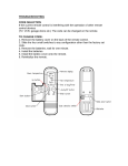
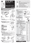
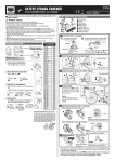
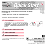
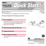
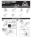
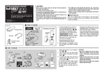
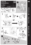
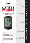
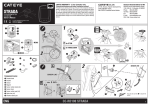
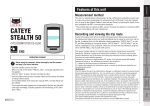
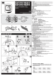
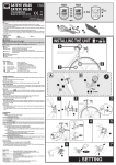
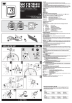
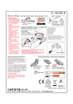
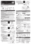
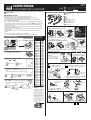
ENG
CATEYE STRADA
U.S. Pat. Nos. 5236759/6957926 Pat./Design Pat. Pending
Copyright© 2008 CATEYE Co., Ltd.
CCRD10-080924 066600507 6
CYCLOCOMPUTER CC-RD100N
Before using the computer, please thoroughly read this manual and keep it for
future reference.
How to install the unit on your bicycle
2
WARNING / CAUTION
• Do not concentrate on the computer while riding. Ride safely!
• Install the magnet, sensor, and bracket securely. Check these periodically.
• If a child swallows a battery, consult a doctor immediately.
• Do not leave the computer in direct sunlight for unnecessary or extended periods.
• Do not disassemble the computer.
• Do not drop the computer. Doing so may result in a computer malfunction or damage.
• When using the computer installed on the bracket, change the MODE by pressing on the
three dots below the screen. Pressing hard on other areas can result in malfunction or
damage to the computer.
• Never place the computer on a metal surface. If you do, the contact points will conduct
electricity, discharging the battery.
• Tighten the dial on the Flex-Tight bracket by hand only. Over-tightening can damage the
bracket threads.
• When cleaning the computer, bracket and sensor, do not use thinners, benzene, or
alcohol.
• Dispose of used batteries according to local regulations.
• LCD screen may be distorted when viewed through polarized sunglass lenses.
Preparing the computer
Tire circumference
reference table
When the computer is
AC
Battery case cover mounted on the bracket
Push!
MENU
Contact
MODE
: Speed unit
: Wheel size icon
all data (initialization)
1 Clear
Press the AC button on the back.
AC
the desired speed units
2 Select
Select “
” or “
”.
km/h ↔ mph
Register the
setting
MENU
MODE
the tire circumference
3 Enter
Enter the tire circumference of your bicycle in
mm.
* Refer to the tire circumference reference table.
Increase
MODE
MODE
Move digits
Register
(by pressing
the setting
& holding) MENU
the clock
4 Set
When MODE is pressed and held, “Displayed
time”, “Hour”, and “Minute” will appear, in
this order.
MODE
24h ↔ 12h,
or increase
the value
Register
Switch the
screen or
the
setting
move digits
MENU
(finish)
MODE (by pressing
& holding)
Tire size
12 x 1.75
14 x 1.50
14 x 1.75
16 x 1.50
16 x 1.75
18 x 1.50
18 x 1.75
20 x 1.75
20 x 1-3/8
22 x 1-3/8
22 x 1-1/2
24 x 1
24 x 3/4 Tubular
24 x 1-1/8
24 x 1-1/4
24 x 1.75
24 x 2.00
24 x 2.125
26 x 7/8
26 x 1(59)
26 x 1(65)
26 x 1.25
26 x 1-1/8
26 x 1-3/8
26 x 1-1/2
26 x 1.40
26 x 1.50
26 x 1.75
26 x 1.95
26 x 2.00
26 x 2.10
26 x 2.125
26 x 2.35
26 x 3.00
27 x 1
27 x 1-1/8
27 x 1-1/4
27 x 1-3/8
650 x 20C
650 x 23C
650 x 35A
650 x 38A
650 x 38B
700 x 18C
700 x 19C
700 x 20C
700 x 23C
700 x 25C
700 x 28C
700 x 30C
700 x 32C
700C Tubular
700 x 35C
700 x 38C
700 x 40C
29 x 2.1
29 x 2.3
L (mm)
935
1020
1055
1185
1195
1340
1350
1515
1615
1770
1785
1753
1785
1795
1905
1890
1925
1965
1920
1913
1952
1953
1970
2068
2100
2005
2010
2023
2050
2055
2068
2070
2083
2170
2145
2155
2161
2169
1938
1944
2090
2125
2105
2070
2080
2086
2096
2105
2136
2146
2155
2130
2168
2180
2200
2288
2326
Measure wheel
circumference (L) of
your bike
To get the most accurate
calibration do a wheel roll
out. With the valve stem
perpendicular to the ground,
mark the pavement at the
valve stem. With the riders
weight on the bike, roll the
wheel one tire revolution in a
straight line and mark the
ground when the valve stem
is perpendicular to the
ground again. Measure the
distance in millimeters. This
is the most accurate wheel
calibration number.
L mm
6
5
1
7
3
8
4
0
9
1
1 Bracket band
2 Bracket
3 Nut
4 Sensor
5 Magnet
6 Sensor rubber band (x2)
7 Sensor hook
8 Sensor rubber pad (x3)
9 Bracket rubber pad
0 Nylon ties (x5)
Attach the bracket to the stem or handlebar
Stem
When attaching the bracket to the stem
9
2
Cut
1
Caution:
Round off the cut edge
of the bracket band to
prevent injury.
Caution:
Tighten the bracket, ensuring that the cable does
not get caught in the stem.
When attaching the bracket to the handlebar
9
Handlebar
3
2
1
Caution:
Tighten the bracket, ensuring that the cable does not get caught in the handlebar.
2
* For wing type handlebar or
oversized stem, bracket can be
mounted using the Bracket
Holder and nylon ties. (Option).
Wrap the cable around
the front brake cable
Caution:
Turn the handlebar to
make sure wire does
not hinder full rotation.
2
To the sensor
Install the sensor and magnet :
A
The magnet should pass
through the sensor line.
B
Inside of right
front fork
4
The clearance between the sensor surface
and the magnet must not exceed 5 mm.
5 mm
5
4
Sensor line
3
Inside of right
front fork
* Attach between one and three sensor pads 8,
putting them together as required.
5
Install the sensor
4
0
Inside of right
front fork
Pull securely
7
6
* You can also use ties 0 (in place of sensor rubber
band 6) to secure the sensor.
4
Install the magnet
5
Remove/install the computer
While supporting it by hand,
Spoke
Click
5
Toward the sensor line
push it out as if lifting the front up
* After installation, rotate the front wheel gently to check that the speed is displayed on the
computer. If the speed is not displayed, check that conditions A and B are satisfied.
CC-RD100N
Operating the computer [Measuring screen]
Tm Elapsed Time
Indicates whether the current speed
is faster ( ) or slower ( ) than the
average speed.
0:00’00” - 9:59’59”
Current speed
Dst Trip Distance
0.00 - 999.99 km [mile]
0.0(4.0) - 200.0 km
[0.0(3.0) - 125.0 mph]
Dst 2 Trip Distance-2
Selected Mode
0.00 - 999.99 /
1000.0 - 9999.9 km [mile]
Av Average Speed*2
0.0 - 200.0 km/h
[0.0 - 125.0 mph]
Mx Maximum Speed
MODE
0.0(4.0) - 200.0 km/h
[0.0(3.0) - 125.0 mph]
*1
Troubleshooting
Pace arrow
Odo Total Distance
0.0 - 9999.9 /
10000 - 99999 km [mile]
Clock
0:00 - 23:59
or 1:00 - 12:59
*1 With the computer installed on the
bracket, press on the three raised dots on
the face of the computer.
*2 If Tm exceeds approximately 27 hours or
Starting/Stopping measurement
Measurements occur automatically
when the bicycle is in use. During
measurement,
or
flashes.
Switching computer function
Pressing MODE switches function,
in order, as shown on the left.
Resetting data
To reset measurement data, display
any data other than for Dst-2 and then
press and hold MODE. Pressing and
holding MODE with Dst-2 displayed
resets Dst-2 only.
The total distance is never reset.
Power-saving function
If the computer has not received
any signal for an hour, powersaving mode will activate and only
the clock will be displayed.
Dst exceeds 999.99 km, .E (Error) is Alternatively, if the sensor detects a
displayed as the average speed. Reset data. signal or MODE is pressed, the main
display reappears.
MODE does not work when the computer is mounted on its bracket.
Check that there is no dirt between the bracket and the computer.
Wash off the bracket with water to get rid of any dirt, and to ensure that the computer slides in and out
smoothly.
Speed and distance are not displayed. (Touch a metal item against two contact points of the computer
several times to create a short circuit while observing the display. If a numeric value appears, this signifies
that the computer is functioning normally.)
Is the clearance between the sensor and magnet too great? (must be ≤ 5 mm)
Does the magnet pass through the sensor line?
Adjust the positions of the magnet and sensor.
Is there any foreign matter (which would prevent a clean contact) on the contact points of the computer
and/or bracket?
Clean the contact points.
Check that no wire cable is worn or broken. Even with a normal appearance, it may be that a wire cable
could be broken internally. Replace the bracket sensor set.
No display.
Is battery in the computer run down?
Replace it. Then reinitialize the computer referring to “Preparing the computer”.
Incorrect data appear.
Reinitialize the computer referring to “Preparing the computer”.
Specification
Battery ...................................... Lithium battery (CR1620) x 1
Battery life ................................ Approx. 3 years (Using the battery one hour a day; the battery life will vary with the
conditions of use.)
Controller .................................. 4-bite, 1-chip microcomputer (Crystal controlled oscillator)
Display ...................................... Liquid crystal display
Sensor ...................................... No contact magnetic sensor
Wheel circumference range ..... 0100 mm - 3999 mm (Default figure A: 2096 mm, B: 2096 mm)
Working temperature ............... 32 °F - 104 °F (0 °C - 40 °C) (This product will not display appropriately when exceeding the
Working Temperature range. Slow response or black LCD at lower or higher temperature
may happen respectively.)
Dimensions/weight ................... 1-53/64” x 1-7/32” x 19/32” (46.5 x 31 x 15 mm) / 0.63 oz (18 g)
* The factory-loaded battery life might be shorter than the above-mentioned specification.
* The specifications and design are subject to change without notice.
Changing the computer settings [menu screen]
Standard parts
To bring up the menu screen, press MENU in any mode.
Each time MODE is pressed, the relevant menu screen appears. Pressing and
MENU
holding MODE changes the setting of the displayed menu.
#160-0280
Bracket band
#160-0290N
Parts kit
#160-0270N
Bracket/Sensor
#160-0291N
Rear long cable
MODE
#169-9691
Wheel magnet
MODE
Wheel
selection
MODE
MODE
Wheel size
entry
Setting change
(by pressing &
holding)
MODE
Clock setting
Total distance
manual entry
Speed unit
LIMITED WARRANTY
Wheel selection ..... Toggle between the specified wheel size (tire circumference)
and
. Use this function if the computer is to be shared
between two bicycles.
and
.
Pressing MODE toggles between
Wheel size entry .... Pressing MODE increases the value, and pressing and
holding MODE moves to the next digit.
, display
using “Wheel selection”.
* To enter the wheel size
Clock setting .......... To set the clock, refer to “Preparing the computer-4”.
Total distance manual entry
................................ Before reinitializing the computer, note the total distance. This
reading will later allow you to enter the total distance
manually. Pressing MODE increases the value, and pressing
and holding MODE moves to the next digit.
Speed unit .............. Pressing MODE toggles between
and
.
Maintenance
To clean the computer or accessories, use diluted neutral detergent on a soft cloth,
and wipe it off with a dry cloth.
Replacing the battery
Close
Open
Optional Parts
#160-2770
Bracket holder
MODE
* After changing, be sure to press MENU to register
the setting.
* If the menu screen is not touched for a minute, the
Measuring screen reappears without data changes.
If the display appears faded, replace the battery.
Install a new lithium battery (CR1620) with the (+)
side facing upward. Then reinitialize the computer
referring to “Preparing the computer”.
#169-6180
Lithium battery (CR1620)
CO
IN
CR1620
2-Year Computer only
(Accessories/Bracket sensor and Battery Consumption excluded)
CatEye cycle computers are warranted to be free of defects from materials and workmanship for a period of two years
from original purchase. If the product fails to work due to normal use, CatEye will repair or replace the defect at no
charge. Service must be performed by CatEye or an authorized retailer.
To return the product, pack it carefully and enclose the warranty certificate (proof or purchase) with instruction for
repair. Please write or type your name and address clearly on the warranty certificate.
Insurance, handling and transportation charges to CatEye shall be borne by person desiring service.
For UK and REPUBLIC OF IRELAND consumers, please return to the place of purchase. This does not affect your statutory
rights.
CO.,LTD.
2-8-25, Kuwazu, Higashi Sumiyoshi-ku, Osaka 546-0041 Japan
Attn: CATEYE Customer Service Section
Service & Research Address for USA
CatEye North America
2300 Central Ave Suite L Boulder, CO 80301
Phone: 303.443.4595
Toll Free: 800.5CATEYE
Fax:
303.473.0006
E-mail: [email protected]
URL:
http://www.cateye.com