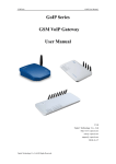
1
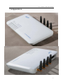
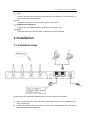
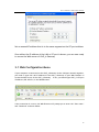
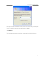
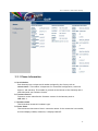
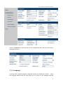
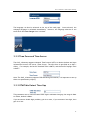
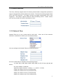
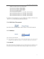
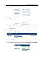
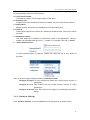
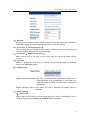
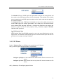
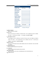
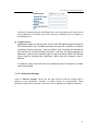
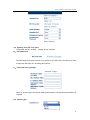
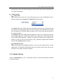
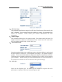
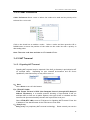
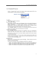
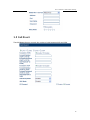
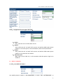
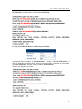
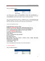
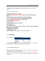
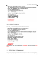
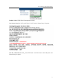
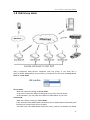
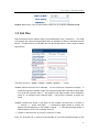
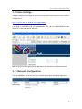
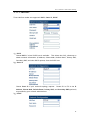
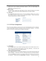
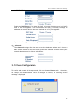
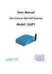
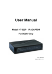
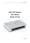
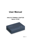
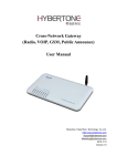
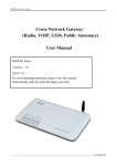
User Manual
Four Channel’s GSM VoIP Gateway
Model: GoIP_4
Four Channel’s GSM VoIP Gateway
1
Four Channel’s GSM VoIP Gateway
Contents
1 Product Introduction.................................................... 4
1.1 General Information........................................................................................................4
1.2 Protocol .............................................................................................................................4
1.3 Hardware Specification ..................................................................................................5
1.4 Software Specification ...................................................................................................5
1.5 List of the Package..........................................................................................................5
1.6 Appearance.......................................................................................................................6
2 Installation .................................................................... 7
2.1 Installation Steps .............................................................................................................7
2.3 LED Indicators ..................................................................................................................8
2.4 SMS Commands.................................................................................................................8
3 Configuration Guide ..................................................... 9
3.1 Web Configuration Menu ..............................................................................................10
3.2 Status...............................................................................................................................11
3.2.1 Phone Information .............................................................................................12
3.2.2 Network Information .........................................................................................13
3.2.3 GSM Module Information...................................................................................13
3.3 Configurations................................................................................................................13
3.3.1 Language .............................................................................................................14
3.3.2 Time Zone and Time Server..............................................................................15
3.3.3 DTMF Min Detect Time Gap ..............................................................................15
3.3.4 Auto-Provision.....................................................................................................16
3.3.5 Network Tone......................................................................................................16
3.3.6 GSM Caller ID Anonymous .................................................................................17
3.3.7 GSM Band.............................................................................................................17
3.3.8 GSM ISP ................................................................................................................17
3.3.9 SMS Sender ..........................................................................................................18
3.3.10 Auto Reboot ......................................................................................................18
3.4 Call Settings ...................................................................................................................18
3.4.1 H.323 Phone ........................................................................................................18
3.4.1.1 Direct Mode .............................................................................................19
3.4.1.2 Gatekeeper Mode ...................................................................................19
3.4.1.3 Advance Settings.....................................................................................20
3.4.2 SIP Phone .............................................................................................................22
3.4.2.1 Advanced Settings ..................................................................................24
3.4.3 Media Setting ......................................................................................................26
3.4.4 Codec Preference...............................................................................................28
3.4.5 NAT Traversal ......................................................................................................28
3.4.5.1 Signaling NAT Traversal..........................................................................28
2
Four Channel’s GSM VoIP Gateway
3.4.5.2 Media NAT Traversal ...............................................................................29
3.5 Call Divert.......................................................................................................................30
3.5.1 Call Forward (From VoIP To PSTN) ..................................................................31
3.5.2 Auto Forward Call To PSTN ...............................................................................31
3.5.3 Call Forward (From PSTN To VoIP) ..................................................................32
3.5.4 Auto Forward Call To VoIP.................................................................................32
3.6 SMS Disposal ...................................................................................................................32
3.6.1 SMS Call Out........................................................................................................32
3.6.2 SMS Relay.............................................................................................................36
3.6.2.1 SMS Relay To VoIP System......................................................................36
3.6.2.2 SMS Relay To GSM Network ...................................................................37
3.7 PSTN Caller ID Transparent ..........................................................................................37
3.8 GSM Group Mode............................................................................................................40
3.9 Dail Plan ..........................................................................................................................41
3.10 Gain Settings… .............................................................................................................43
3.11 Network Configuration ...............................................................................................43
3.11.1 LAN Port.............................................................................................................44
3.11.2 PC Port Configurations ....................................................................................45
3.12 Save Configuration ......................................................................................................46
3.13 Discard Changes...........................................................................................................47
3.14 Tools Menu ....................................................................................................................47
3.14.1 Online Upgrade.................................................................................................47
3.14.2 Change Password..............................................................................................48
3.14.3 Reset Configuration .........................................................................................48
3.14.4 Reboot the Device............................................................................................48
4 Hardware Specifications ............................................ 49
5 Manufactory Parameters ............................................ 49
3
Four Channel’s GSM VoIP Gateway
1 Product Introduction
1.1 General Information
A VoIP GSM Gateway enables direct routing between IP and GSM network without the use
of a FXO port or the PSTN network. With this device, the usage of VoIP is greatly
enhanced with significant savings on long distance and roaming charges.
1.2 Protocol
¾
¾
¾
¾
¾
¾
¾
¾
¾
¾
TCP/IP V4 (IP V6 auto adapt)
ITU-T H.323 V4 Standard
H.2250 V4 Standard
H.245 V7 Standard
H.235 Standard(MD5,HMAC-SHA1)
ITU-T G.711 alaw/ulaw, G.729A, G.729AB, and G.723.1 Voice Codec
RFC1889 Real Time Data Transmission
Proprietary Firewall-Pass-Through Technology
SIP V2.0 Standard
Simple Traversal of UDP over NAT (STUN)
4
Four Channel’s GSM VoIP Gateway
¾
¾
¾
¾
¾
¾
¾
¾
¾
¾
Web-base Management
PPP over Ethernet (PPPoE)
PPP Authentication Protocol (PAP)
Internet Control Message Protocol (ICMP)
TFTP Client
Hyper Text Transfer Protocol (HTTP)
Dynamic Host Configuration Protocol (DHCP)
Domain Name System (DNS)
User account authentication using MD5
Out-band DTMF Relay: RFC 2833 and SIP Info
1.3 Hardware Specification
¾
¾
¾
¾
¾
ARM9E Processor
DSP for voice codec and voice processing
Two 10/100 BaseT Ethernet ports with full compliant with IEEE 802.3
LEDs for Ethernet port status
Four GSM Channels’ Connection
1.4 Software Specification
¾
¾
¾
¾
¾
¾
¾
¾
¾
¾
¾
¾
¾
LINUX OS
Built-in HTTP Web Server
PPPoE Dial-up
NAT Broadband Router Functions
DHCP Client
DHCP Server
Firmware On-line upgrade
PSTN Caller ID transmit
Multiple Language Support
Supported call divert
Supported PSTN auto call out to PSTN
Supported Multi_devices Cooperate Mode(Group Mode)
Supported SMS call out
1.5 List of the Package
a)
b)
c)
One GoIP_4 Gateway main unit
One DC12V/2000mA power adaptor
One Ethernet cable (3M)
5
Four Channel’s GSM VoIP Gateway
1.6 Appearance
6
Four Channel’s GSM VoIP Gateway
1) LAN
Connect this port to an Ethernet Switch/Router, the Ethernet of a DSL modem, or
other network access equipment.
2) PC
Connect a computer or other network device to this port.
3) POWER (DC12V/2000mA)
Connect the 12V/2000mA Adapter provided to this power jack.
4) Reset
Press this button to reset the GoIP_4 Gateway to factory defaults.
2 Installation
2.1 Installation Steps
Please follow the connection diagram above to install the GoIP_4 Gateway.
a)
b)
Insert a GSM SIM card in the SIM card compartment located at the bottom of the
GoIP_4 Gateway’s.
Connect an Ethernet cable the LAN port of the GoIP_4 Gateway and the other end to
your existing network equipment.
7
Four Channel’s GSM VoIP Gateway
c)
d)
Connect an Ethernet cable to the PC Port of the GoIP_4 Gateway and the other end
to a PC or other network device (Optional).
Connect the power adapter provided to the power jack of the GoIP_4 Gateway.
2.3 LED Indicators
The following table defines the status of the LEDS located on the top case and on the
RJ-45 connectors.
LED
DESCRIPTION
P0WER
When GoIP_4 Working, this LED will keep
light;
RUN
1. When the GoIP_4 is booting,this LED
will flash 100ms ON and 100ms OFF.
2. When the GoIP_4 is login your
softswitch, this LED will flash 1s ON and
1s OFF.
LAN
When LAN port connecting to network,this
LED will light and flash when has data
through this port;
PC
When has devices use PC port,this LED will
light and flash;
Channel 1
When the GoIP_4’s GSM channel1 login to
ISP’s system, this LED will flash 1s ON and
1s OFF;
Channel 2
When the GoIP_4’s GSM channel2 login to
ISP’s system, this LED will flash 1s ON and
1s OFF;
Channel 3
When the GoIP_4’s GSM channel3 login to
ISP’s system, this LED will flash 1s ON and
1s OFF;
Channel 4
When the GoIP_4’s GSM channel4 login to
ISP’s system, this LED will flash 1s ON and
1s OFF;
2.4 SMS Commands
GoIP_4 supported some maintenance commands come from SMS.
8
Four Channel’s GSM VoIP Gateway
FUNCTION
SMS
CONTENT
REMARK
Obtain LAN Port Info
INFO
Not distinguish majuscule and lowercase
Reset device
RESET Password
Not distinguish majuscule and lowercase
Reboot device
REBOOT Password
Not distinguish majuscule and lowercase
Note:In command Reset and Reboot, the Password is the GoIP_4 device’s admin
password.
The command keywords can use majuscule and lowercase, but the password must
distinguish majuscule or lowercase.
3 Configuration Guide
To configure the GoIP_4 Gateway, you must login to its Web server via the LAN or PC port.
The LAN port is factory preset to obtain an IP from the local DHCP host and the PC port is
set to the fixed IP 192.168.8.1.
If a local DHCP host is available, the LAN will obtain an IP address automatically. To listen
to the IP address assigned, just dial a call via the GoIP_4 Gateway’s SIM card phone
number. When the call is connected, you will hear a dial tone. Just dial “*01#” for
English voice prompt on the LAN IP and “*00#” for Chinese voice prompt on the LAN IP.
The LAN IP Address can also be obtained by sending a SMS message to the GSM phone
number. The GoIP_4 will then reply with a SMS message containing the LAN IP address.
If you want obtained LAN port IP by sending a SMS message, please send” INFO “or”
info”.
If a local DHCP host is not available, you can then access the GoIP_4 Gateway via the PC
port. You will need to change your computer’s LAN configuration via the Network
Connections under the Control Panel.
Windows: Control Panel--ÆNetwork Connections--ÆLocal
Connectionism’s Property--ÆTCP/IP Protocol’s Property
9
Four Channel’s GSM VoIP Gateway
Set an unused IP address that is in the same segment as the PC port address.
Once either the IP address of the LAN or PC port is known, you are now ready
to access the Web server of GoIP_4 Gateway.
3.1 Web Configuration Menu
If your computer is connected to the GoIP_4 Gateway via the LAN port network segment,
you need to type the LAN IP address of the GoIP_4 Gateway in your Web Browser to
access the Web server of the GoIP_4 Gateway. If not, you should type GoIP_4’s PC port
IP address (192.168.8.1) in the Web Browser.
If the connection is correct, the Web Browser will prompt you to enter the “User name”
and “Password” as shown below.
10
Four Channel’s GSM VoIP Gateway
Enter the User name and Password and the press OK to access the GoIP_4 Gateway Web
Server. The default for both user name and password is “admin”.
3.2 Status
The Status page shown below is the default / home page of the GoIP_4 Web server.
11
Four Channel’s GSM VoIP Gateway
3.2.1 Phone Information
A. Serial Number
Each Gateway has a unique serial number assigned by the factory such as
GOIP409100019. This number is important for centralized configuration, technical
support, and warranty. This number is printed on the bottom of the Gateway and is
associated with your software license.
B. Firmware Version
Firmware version identifies the firmware version of the Gateway such as
GHS-4.01-1.
C. Hardware Mode
This field shows terminal’s hardware type.
D. Phone Status
This field shows the status of Line’s connection status. If the connection is successful,
this field displays LOGIN; otherwise, it displays LOGOUT.
12
Four Channel’s GSM VoIP Gateway
3.2.2 Network Information
A. LAN Port Configuration
This field displays the status of the LAN port.
B. PC Port Configuration
This field displays the status of the LAN port.
C. PPPoE
If PPPoE is enabled, it displays its status.
D. Default Route
This field displays the IP address of the default routing Gateway.
E. DNS Server
This field displays the IP address of the Domain Name Server.
3.2.3 GSM Module Information
A. GSM Module
This field displays the GSM module type.
B. GSM Signal
This field displays the GSM signal status.
C. GSM Status
This field shows the status of GSM connection status. If the connection is successful,
this field displays LOGIN; otherwise, it displays LOGOUT.
3.3 Configurations
Click on the “Configurations” tab on the left hand column to access the device
configuration menu: Preference, Network, Call Settings, Call Divert, Save Changes,
and Discard Changes.
13
Four Channel’s GSM VoIP Gateway
Click on “Preference” in the left menu of the configuration web, and the screen will be
displayed as below:
3.3.1 Language
Currently GoIP_4 supports English, Simplified Chinese and Traditional Chinese. Select
the language desired and the Web page will be shown in the language selected
14
Four Channel’s GSM VoIP Gateway
accordingly.
The language can also be selected at the top of the web page. Once selected, the
webpage language is refreshed immediately. However, the language selection is not
saved until the Save Changes icon is clicked.
3.3.2 Time Zone and Time Server
The GoIP_4 Gateway supports Network Time Protocol (NTP) to obtain the date and time
information from an NTP server (Time Server). The time zone is specified as in GMT ±
offset. For example, the Pacific Standard Time is GMT-8, and the Pacific Daylight Time
is GMT-7.
Note: The GoIP_4 Gateway supports CDR and Billing Information, it is important to set up
these two parameters properly.
3.3.3 DTMF Min Detect Time Gap
This parameter use to limit two same DTMF digit’s minimum time gap, the range is 60ms
to 120ms, default is 80ms.
If you encounter double digit problem, gain it to more, if you encounter lose digit, then
gain it to less.
15
Four Channel’s GSM VoIP Gateway
3.3.4 Auto-Provision
The GoIP_4 Gateway supports Auto Provisioning which enables configuration parameters
to be set automatically without human intervention. The Auto Provisioning supports both
HTTP and TFTP protocols. For higher security, encrypted configuration file is also
supported. This feature requires external Auto Provisioning Server. Please contact
your service provider for further information on this.
3.3.5 Network Tone
Network Tones are a set of tones used for VoIP calls. Select one of the countries
defined or customized to define your own Network Tones.
You can configure the Network Tones as Customized option:
Each tone listed above is defined in the following format:
nc, rpt, c1on, c1off, c2on, c2off, c3on, c3off, f1, f2, f3, f4, p1, p2, p3, p4
Where:
nc is the number of cadences
rpt is the repeat counter(0 - infinite, 1~n - repeat 1~n times)
c1on is the cadence one on (in milliseconds)
c1off is the cadence one off (in milliseconds)
c2on is the cadence two on (in milliseconds)
c2off is the cadence two off (in milliseconds)
16
Four Channel’s GSM VoIP Gateway
c3on is the cadence three on (in milliseconds)
c3off is the cadence three off (in milliseconds)
f1 is the tone #1 frequency (300Hz-3000Hz)
f2 is the tone #2, frequency (300Hz-3000Hz)
f3 is the tone #3 frequency (300Hz-3000Hz)
f4 is the tone #4 (300Hz-3000Hz)
p1 is the attenuation index for f1, 0~31(0=3dB,
p2 is the attenuation index for f2, 0~31(0=3dB,
p3 is the attenuation index for f3, 0~31(0=3dB,
p4 is the attenuation index for f4, 0~31(0=3dB,
-1dB
-1dB
-1dB
-1dB
increments)
increments)
increments)
increments)
For example, the tone definition for a tone of 450Hz with a cadence of 700 ms on and
1000 ms off is 1,0,700,1000,0,0,0,0,450,0,0,0,20,0,0,0
3.3.6 GSM Caller ID Anonymous
Some GSM ISP allows the caller disable it phone number, it must GSM ISP supported;
3.3.7 GSM Band
GoIP_4 Supported quad GSM bands;
Note: About GSM bands supported, it base as which model GSM module we was used, some old
GoIP gateway just supported two bands, so it will different at differ batch’s GoIP devices;
3.3.8 GSM ISP
When GoIP searched more ISP signaling it can use, GoIP will show you a GSM ISP list, you
can choice any one ISP and the GoIP will lock itself just register to your choice one;
17
Four Channel’s GSM VoIP Gateway
3.3.9 SMS Sender
3.3.10 Auto Reboot
This option enable GoIP_4 auto reboot each day, GoIP_4 will auto reboot itself at Reboot
Time. If meet a current called, the action will auto delay after the call finish.
3.4 Call Settings
Click on the “Call Settings” to configure the VoIP call settings. The first thing to set is
the Endpoint Type: H.323 or SIP.
3.4.1 H.323 Phone
For H.323 protocol, 2 Endpoint Modes are supported: Direct Mode and Gatekeeper
Mode.
18
Four Channel’s GSM VoIP Gateway
3.4.1.1 Direct Mode
In Direct Mode, GoIP_4 running at H.323 P to P type.
A. H.323 Phone Number
H.323 phone number: fill the login number (E164) here.
B. Display Name
Display name is the name to be displayed on the called VoIP party.
C. H.323 ID
If the system requires an H.323 ID as a method of Authentication, enter the H.323 ID
provided.
D. Default Voice Gateway
This field assigns the IP address or the domain name of the gatekeeper or other VoIP
gateway. The port number can be added with the colon “:” symbol. For example:
192.168.1.70:8080.
GoIP_4 will send out all VoIP calls to this address.
3.4.1.2 Gatekeeper Mode
19
Four Channel’s GSM VoIP Gateway
The “Gatekeeper Mode” mode allows a user to setup the GoIP_4 Gateway by registering
to the gatekeeper with one H.323 account.
A. H.323 Phone Number
H.323 phone number: fill the login number (E164) here.
B. Gateway Prefix
If login with a Prefix method fill the prefix number (do not fill the Phone number).
C. Display Name
Display name is the name to be displayed on the called VoIP party.
D. H.323 ID
If the system requires an H.323 ID as a method of Authentication, enter the H.323 ID
provided.
E. Gatekeeper Address
This field assigns the IP address or the domain name of the gatekeeper. The port
number can be added with the colon “:” symbol. For example: 192.168.1.70:8080.
F. Enable Authentication
If H.235 Authentication is required, enable this field and fill in the values as
provided.
GoIP_4 has three types configure modes in Gatekeeper Mode;
Configure By Single: All four channels use same one H.323 account connect to
gatekeeper;
Configure By Line: Each channel will use a single account connect to H.323
gatekeeper;
Configure By Group: Each VoIP channel will register to Gatekeeper base differ
Group;
3.4.1.3 Advance Settings
Click “Advance Settings” to access additional H.323 parameters as shown below.
20
Four Channel’s GSM VoIP Gateway
A) RAS Port
RAS Port is an unreliable channel which is used to convey the registration, admissions,
bandwidth change, and status messages between two H.323 entities.
B) Q.931 Port ( Call Signaling Port )
Call Signaling Port is a reliable channel which is used to convey the call setup and
release messages between two H.323 endpoints.
C) H.245 Port ( Media Control Ports )
Media control port is the port or port range used by the H.245 media control
protocol.
D) Fast Start
Enable or disable the Fast Start in H.225.0. Most H.323 terminals or Gateways
support the Fast Start feature.
E) Register Mode
Register Multiple Numbers: The GoIP_4 Gateway sends registration request in one
signaling packet to the gatekeeper. In the mode, one
signaling packet includes two VoIP line’s registration
information.
Register Multiple Times: In this mode, the GoIP_4 Gateway will register like two
terminals.
F) DTMF Signaling
1) DTMF TYPE
DTMF signals can be sent over to the called party once a call is established. GoIP_4
Gateway supports both Inband and Outband DTMF signal types.
21
Four Channel’s GSM VoIP Gateway
For Inband DTMF type, DTMF signals are generated locally at the calling phone and
then send to the called party as part of the voice signals. This method is not reliable
since the quality of the DTMF signals is subject to the Codec used and the quality of
the network traffics.
For Outband DTMF type, DTMF signal commands are sent to the called party and the
actual DTMF signals are actually generated by the called party. This method allows
more reliable DTMF signaling. However, it requires the called party to support this
feature in order for this to work properly. GoIP_4 Gateway supports RFC2833
Outband DTMF protocols.
2)DTMF Payload Type
DTMF Payload Type is by RFC2833 protocol to carry the tone definitions for various
applications. The default DTMF Payload Type is 96. Please consult your VoIP service
provider for the proper setting if required.
.
3.4.2 SIP Phone
Set the “Endpoint Type” to SIP Phone for connections to SIP Servers.
GoIP_4 has two types configure modes in SIP protocol;
Configure By Single: All four channels use same one SIP account connect to SIP
server;
Configure By Lines: Each channel will use a private SIP account connect to SIP
server;
GoIP_4 Gateway’s SIP configure page as follow:
22
Four Channel’s GSM VoIP Gateway
A)Phone Number
Enter a SIP phone number.
B)SIP Proxy
Enter the SIP proxy IP address or domain name. If the registration port isn’t 5060,
then add “:” and the port number. An example is sip.dtt.tw:8080.
C)SIP Registrar Server
If the Registrar Server is different from the SIP Proxy, enter its IP address or domain
name in this field.
If the registration port isn’t 5060, then add “:” and the port
number. An example is sip.dtt.tw:8080.
D)Home Domain
SIP Networks sometimes use the Home Domain name as an identifier. Enter this field
as required.
E)Authentication ID
Enter the Authentication ID as provided.
F) Password
Enter the authentication password as provided.
G) Display Name
Enter this field for the name to be displayed on the called VoIP party.
H) Backup Server
23
Four Channel’s GSM VoIP Gateway
The GoIP_4 Gateway supports one Backup Server as an alternative to the main server.
Once registration to the main server fails, the GoIP_4 Gateway will try to register to
the Backup Server.
I) Outbound Proxy
OutBound proxies are devices that will forward SIP signaling (and frequently
RTP media traffic too). OutBound proxies are used for a number of reasons,
including, firewall traversal – both in parallel with a firewall and situated in
the Internet as a Session Border Controller, and also for hiding customer IP
addresses – calls are all routed through one point so that a public ITSP address
can be used for accessing the customers, rather than the customer’s own IP
address.
If required, enter this field with the outbound proxy IP address or domain
name as provided.
3.4.2.1 Advanced Settings
Click on “Advance Settings” tab on the top right corner of the Call Setting page to
display all the parameters available, as shown below, for programming. These
parameters allow more advanced control over the SIP signaling and media preference.
24
Four Channel’s GSM VoIP Gateway
A) Signaling Port (SIP Local port)
The default SIP port is 5060. Change this as required.
B) NAT Keep-alive
The NAT Keep-alive feature sends a null packet to the SIP Proxy periodically in order
to keep the NAT open for incoming data traffics.
C) Advanced Timing Settings
Some SIP proxies may have special timing requirements. Change these parameters as
required.
D) Signaling Qos
25
Four Channel’s GSM VoIP Gateway
Signaling QoS improves the performance of SIP signaling. If local network device
supports Qos, select this field accordingly. Please consult your network administrator
for further information.
E) DTMF Signaling
1) DTMF TYPE
DTMF signals can be sent over to the called party once a call is established. GoIP_4
Gateway supports both Inband and Outband DTMF signal types.
For Inband DTMF type, DTMF signals are generated locally at the calling phone and
then send to the called party as part of the voice signals. This method is not reliable
since the quality of the DTMF signals is subject to the Codec used and the quality of
the network traffics.
For Outband DTMF type, DTMF signal commands are sent to the called party and the
actual DTMF signals are actually generated by the called party. This method allows
more reliable DTMF signaling. However, it requires the called party to support this
feature in order for this to work properly. GoIP_4 Gateway supports both RFC2833
and SIP INFO Outband DTMF protocols.
2)DTMF Payload Type
DTMF Payload Type is by RFC2833 protocol to carry the tone definitions for various
applications. The default DTMF Payload Type is 96. Please consult your VoIP service
provider for the proper setting if required.
3.4.3 Media Setting
Click on “Media Settings” in the “Call Setting” menu to access the parameters available
for media settings.
26
Four Channel’s GSM VoIP Gateway
A) RTP Port Range
This parameter specifies the range of the RTP (Real Time Protocol) Ports used by the
GoIP_4 Gateway. If your network limits the usable port range, this parameter may
need to be modified. Please consult your network administrator for more
information.
B) Packet Length
This parameter defines the voice packet length. The default setting is 20ms. The
range is from 5ms to 40ms at an increment of 5 ms. Please note that some codes
have a minimum packet length of more than 5 ms.
C) Jitter Buffer Mode
Since data packets may arrives at different orders, the Jitter Buffer is used to hold
the data packets received for re-arrangement according to the packet sequence
number. Three Jitter Buffer Modes are supported: Adaptive, Sequential, and Fixed.
The default is set to Adaptive mode with a minimum jitter of 60 ms and a maximum
jitter of 220ms. Please consult your network administrator for more information on
the network environment in order to determine the optimal settings.
D) Media Qos
Similar to the Signaling QoS, the Media Qos in intended to improve the voice
performance or quality If your local network supports QoS
27
Four Channel’s GSM VoIP Gateway
3.4.4 Codec Preference
Codec Preference allows a user to select the codes to be used and its priority to be
selected for a voice call.
Click on the check box to enable a codec. Select a codec and then press the UP or
DOWN button to move the position of the codec on the codec list with a priority in
descending order.
Note: The voice code alaw and ulaw is G.711a and G.711u.
3.4.5 NAT Traversal
3.4.5.1 Signaling NAT Traversal
Signaling NAT traversal may be required if the GoIP_4 Gateway is put behind a NAT
(or multiple NATs). Depending on your network environment and SIP Server
capabilities, this feature may or may not be turn on.
A) None
Select None to turn off this feature.
B) STUN (RFC 3489)
STUN (Simple Traversal of UDP (User Datagram Protocol) through NATs (Network
Address Translators)) is a network protocol allowing a client behind a NAT (or
multiple NATs) to find out its public address, the type of NAT it is behind and the
internet-side port associated by the NAT with a particular local port.
Select STUN (RFC 3489) to use a STUN server for Signaling NAT Traversal. Enter the
IP Address or the domain name of the STUN server to be used.
C) Relay Proxy
Relay proxy is a proprietary NAT traversal technology. Please consult your service
28
Four Channel’s GSM VoIP Gateway
provider for more information.
3.4.5.2 Media NAT Traversal
Similar to Signaling NAT Traversal, this feature allows media packets (RTP) to be
routed properly in various network environments.
A) None
Select None to disable this feature.
B) STUN (RFC 3489 )
STUN (Simple Traversal of UDP (User Datagram Protocol) through NATs (Network
Address Translators)) is a network protocol allowing a client behind a NAT (or
multiple NATs) to find out its public address, the type of NAT it is behind and the
internet-side port associated by the NAT with a particular local port.
Select STUN(RFC 3489) to use a STUN server for Signaling NAT Traversal. Enter the IP
Address or the domain name of the STUN server to be used.
C)Port forwarding Support
Port forwarding (sometimes referred to as tunneling) is the act of forwarding a
network port from one network node to another. This technique can allow an
external user to reach a port on a private IP address (inside a LAN) from the outside
via a NAT-enabled router.
In order for this feature to work, the local network Gateway must support this
feature and be set up properly. Please consult your network administrator for help
to enable this Port forwarding feature.
D) Relay Proxy
Relay proxy is a proprietary NAT traversal technology. Please consult your service
provider for more information.
Currently, the following 3 kinds of packaging mechanism are supported:
¾ Mode 1: The media uses UDP packets and (or) encrypt with multiple UDP port;
¾ Mode 2: The media uses UDP packets and (or) encrypt with single UDP port;
¾ Mode 3: The media uses TCP packets and (or) encrypt (UDP over TCP).
29
Four Channel’s GSM VoIP Gateway
3.5 Call Divert
The Call divert feature controls the routing of calls between VoIP and GSM.
30
Four Channel’s GSM VoIP Gateway
3.5.1 Call Forward (From VoIP To PSTN)
Forward Number
Enter this field to forward all incoming VoIP calls to this number (PSTN or Mobile).
Using “,” to add a 500ms delay to the dialing sequence. If this field is blank, calls will
not be forwarded. The GoIP_4 Gateway answers an incoming VoIP call and generates a
dial tone. The caller can then dial a number (PSTN or Mobile) desired. Please see
below if the
Forward Password
This field sets the password protection for using the GSM connection. If a password is
entered, the GoIP_4 Gateway will generate an indication tone and wait for the call to
dial the
3.5.2 Auto Forward Call To PSTN
When above option has parameter; GoIP_4 will auto forward all VoIP call to this phone
number;
When GoIP_4 Call divert options “Forward Number (VoIP To PSTN)” is empty, GoIP_4 has
a default call forward rule.
A: When the be Callee ID is GoIP_4’s SIP account number, GoIP_4 will take the call and
feed back a dial tone to VoIP caller; The means is VoIP caller must dial PSTN number
when hear this dial tone.
B: When the Callee ID isn’t GoIP_4’s SIP account number, GoIP_4 will auto dial out this
number thru GSM network.
C:At this moment, “Dial Plan(VoIP to PSTN)”still working.
31
Four Channel’s GSM VoIP Gateway
3.5.3 Call Forward (From PSTN To VoIP)
Forward Number
Forward all incoming calls from the GSM connection to the VoIP number specified in this
field. Forward Password is not required once this field is set. If this field is blank, the
GoIP_4 answers an incoming GSM calls and then generates the VoIP dial tone. Please
see below if the Forward Password is set. The caller can then dial a VoIP number
manually. At the end, a pound (#) can be dialed to activate the dialing of the VoIP
number immediately. If not, the VoIP number is dialed after a preset timeout.
Forward Password
This field sets the password protection for incoming GSM calls. If a password is entered,
the GoIP_4 Gateway will generate an indication tone after answering an incoming call.
The caller is then ready to dial the password. Once the password is correctly entered,
the GoIP_4 Gateway generates a VoIP dial tone and waits for the caller to dial a VoIP
number.
3.5.4 Auto Forward Call To VoIP
When GoIP_4’s above option has parameter; GoIP_4 will forward all PSTN incoming call
to this VoIP number;
When GoIP_4 Call divert options “Forward Number (PSTN To VoIP)” is empty, GoIP_4
will auto accept all PSTN incoming call and feed back a dialtone to de caller;
3.6 SMS Disposal
3.6.1 SMS Call Out
GoIP_4 Gateway supported SMS call. In this mode, when GoIP_4 Gateway received a SMS
send from any one mobile phone, it will auto make a call to SIP server.
If you want use this function, select the SMS Dial option in configuration page.
32
Four Channel’s GSM VoIP Gateway
GoIP_4 supported three types SMS Dial:
A:Mode 1
GoIP_4 dial the call use SMS sender call ID
B:Mode 2
GoIP_4 dial the call via itself VoIP account and add the SMS sender phone
number to Call Divet option’s Forward Number (VoIP to PSTN) automatic.
C:Mode 3
GoIP_4 dial the call via itself VoIP account and add the SMS sender phone
number to SIP invites be call number.
D:SMS Dial Prefix
When GoIP_4 dial a SMS call, it will automatic add this option’s digit in be
Called ID.
z
Mode 1 examples:
A. GoIP_4 use SMS Dial Mode 1:
One mobile phone’s number is (86)13800000000, it sends a SMS “8675588228822” to
33
Four Channel’s GSM VoIP Gateway
GoIP_4’s GSM SIM card. When GoIP_4 device receive this SMS, it will auto to call number
8675588228822, and the caller is number 8613800000000.
The sent out signaling as follow:
B. GoIP_4 use SMS Dial Mode 1 and add a prefix as 999:
One mobile phone’s number is (86)13800000000, it sends a SMS “8675588228822” to
GoIP_4’s GSM SIM card. When GoIP_4 device receive this SMS, it will auto to call number
as 9998675588228822, and the caller is number 8613800000000.
The sent out signaling as follow:
34
Four Channel’s GSM VoIP Gateway
z
Mode 2 example:
GoIP_4 use SMS Dial Mode 2:
One mobile phone’s number is (86)13800000000, it sends a SMS “8675588228822” to
GoIP_4’s GSM SIM card. When GoIP_4 device receive this SMS, it will auto to call number
as 8675588228822, and the caller number is GoIP_4’s SIP account number.
GoIP_4 will set the SMS sender number to “Call Divert “option’s “Forward Number (VoIP
to PSTN” automatic. The result is, when SIP server receives the SMS call and call back
this GoIP_4 then GoIP_4 will auto call the SMS sender via GSM network.
The sent out signaling as follow:
Use can add a SMS prefix with mode 2, it will work like mode 1.
z
Mode 3 example:
GoIP_4 use SMS Dial Mode 3:
35
Four Channel’s GSM VoIP Gateway
One mobile phone’s number is (86)13800000000, it sends a SMS “8675588228822” to
GoIP_4’s GSM SIM card. When GoIP_4 device receive this SMS, it will auto to call number
as 8675588228822*(86)13800000000, and the caller number is GoIP_4’s SIP account
number.
The sent out signaling as follow:
Use can add a SMS prefix with mode 3, it will work like mode 1.
3.6.2 SMS Relay
GoIP_4 GSM gateway supported SMS relay.
The SMS Forward Number is the receiver of your VoIP system; it will receive the SMS
send from GoIP_4 when some GSM phones send a SMS to GoIP_4.
3.6.2.1 SMS Relay To VoIP System
When GoIP_4 receive a SMS come from GSM network, it will auto relay to VoIP system’s
appointed number (SMS Forward Number);
Suppose the SMS Forward Number is 3999 and SMS sender number is “8613682626865 “,
the SMS content is “075583185700 “;The GoIP_4 will send a message to your VoIP system
like follow:
36
Four Channel’s GSM VoIP Gateway
3.6.2.2 SMS Relay To GSM Network
When GoIP_4 receive a message come from SIP server as follow:
The GoIP_4 will send a SMS to GSM number 13682626800, the SMS content is “Hello
world”.
3.7 PSTN Caller ID Transparent
In SIP protocol, GoIP_4 support PSTN Caller ID transparent to VoIP via SIP Invite signaling;
37
Four Channel’s GSM VoIP Gateway
Disable: Disable PSTN Caller ID transparent to VoIP;
Use Remote Party ID: GoIP_4 add Caller ID in SIP invite’s Remote Party ID option.
Use CID as SIP Caller ID: GoIP_4 use PSTN Caller ID in SIP invitee’s Caller ID option and
Remote Party ID option.
38
Four Channel’s GSM VoIP Gateway
About H.323’s PSTN Caller ID transmit; we will perfect it in later firmware.
39
Four Channel’s GSM VoIP Gateway
3.8 GSM Group Mode
GoIP_4 supported multi_devices cooperate with one group; it can work like a
multi_channels GSM gateway. Any one GoIP_4’s channels are can work as Group Server
Mode or Client Mode.
Server Mode:
When one channels running in Server Mode;
It can auto forward the GSM’s incoming call to any free client channels.
At this moment, you only offer this channel’s GSM number to your user.
Client Mode:
When one channel running at Client Mode;
It will auto send itself GSM number and state to Server mode channel and waiting the
incoming call forward from Server channel.
You must enter itself GSM number and Server GoIP_4 device’s IP address into follow
40
Four Channel’s GSM VoIP Gateway
option.
Disable: When GoIP_4 run as alone mode, please set all channels to Disable mode.
3.9 Dail Plan
Dial Plan defines how a number (VoIP) is processed when GoIP_4 receives it. This field
is located in the Calling Setting Window and it is available for both H.323 Phone and SIP
Phone. The Dial Plan is very flexible and can be configured for a wide range of dialing
applications.
The basic syntax is “<event>:<action>|<event>:<action>|…”, where
<event> defines the event to be matched. A event consists of a sequence of digits. If
a specific digit has a limited range, use the syntax [A-B] where A and B are both digit
(0 to 9) and B is greater than A. The length of the input number can be limited by
using “X” to represent each unknown digit. If this field is omitted, it means any
event.
<action> defines the action to be taken on the number received and it consists of
“–“ (minus), “+” (plus), and digits. “-“ followed by digits means to remove the
digits from the beginning of the number entered. “+” followed by digits means to
add the digits in front of the number entered.
“|” means or and the order of priority is from left to right.
Note: For practical use, it should not be possible to reach the maximum length of the
41
Four Channel’s GSM VoIP Gateway
Dial Plan string.
Examples:
1. Dial Plan = “010:-010” means that the number dialed out will have the first 3
digits ”010” removed when a number with the first digits as “010” is entered.
a) Number entered = “01082121234”, actual number dialed = “82121234”.
b) Number entered = “82121234”, actual number dialed = “82121234”.
2. Dial Plan = “1:+00” means that the number dialed out will have the “00” added
in front of the number entered when a number with the first digit as “1” is
entered,.
a) Number entered = “1082121234”, actual number dialed = “00182121234”.
b) Number entered = “82121234”, actual number dialed = “82121234”.
3. Dial Plan = “001:-001+1751” means that the number dialed out will the first 3
digits “001” changed to “1751” when a number with the first digits as “001” is
entered.
a) Number entered = “00182121234”, actual number dialed =
“175282121234”.
b) Number entered = “82121234”, actual number dialed = “82121234”.
4. Dial Plan = “XXXX:” means that the input number is limited to 4-digit long and
will be dialed out immediately when the fourth digit is entered.
5. Dial Plan = “13XXXXXXXXX:+0” means that the input number is restricted to
11-digit long and the first two digits must be “13”. When this condition is
matched, the number dialed out will have a leading “0” added.
a) Number entered = “13901234567”, actual number dialed =
“013901234567”.
b) Number entered = “12801234567”, actual number dialed = “12801234567”.
6. Dial Plan = “13[6-9]XXXXXXXX:+0” means that the input number is restricted to
11-digit long and the first two digits must be “13” and the third digit can be 6, 7,
8,or 9. When this condition is matched, the number dialed out will have a
leading “0” added.
a) Number entered = “13901234567”, actual number dialed =
“013971234567”.
b) Number entered = “13001234567”, actual number dialed = “13001234567”.
Please note that the above samples are simple and intended to show the meaning of
various rules. They may not have any practical meaning. A combination of these rules
(joined with the symbol “|”) can be realized for a much more complicated dialing
application.
42
Four Channel’s GSM VoIP Gateway
3.10 Gain Settings…
A hidden webpage is provided to set the receiving and transmit gains of VoIP Chunnel.
The URL link is:
http://xxx.xxx.xxx.xxx/default/en_US/gain.html
THIS PAGE IS INTENDED FOR AN EXPERIENCED USER OR AN ADMINISTRATOR ONLY.
PLEASE SET THE GAINS WITH CAUTIONS.
Note: A too low or too high input gain MAY affect the sensitivity of DTMF detections
3.11 Network Configuration
Click on “Network” tab in the left menu column to configure the LAN and PC ports.
43
Four Channel’s GSM VoIP Gateway
3.11.1 LAN Port
Three LAN Port modes are supported: DHCP, Static IP, PPPoE.
1) DHCP
Choose DHCP if a local DHCP host is available. This allows the GoIP_4 Gateway to
obtain network information (IP Address, Subnet Mask, Default Route, Primary DNS,
Secondary DNS, and other DHCP options) from the DHCP host.
2) Static IP
Choose Static IP if your network topology requires. Please fill in Fill in the IP
Address, Subnet Mask, Default Route, Primary DNS, and Secondary DNS (optional)
as provided by your network administrator.
3) PPPoE
44
Four Channel’s GSM VoIP Gateway
PPPoE is a common dial up method for you network modem (Cable / xDSLs).
Choose this if your network environment requires. Enter the User Name and
Password as provided by your ISP.
4)802.1q VLAN
This QoS feature requires your QoS support of your network to improve voice data
traffics. Please consult your network administrator for proper settings.
5) Advanced…
The Advanced settings allow the user to set the broadcast address and to clone a
MAC address instead of using the factory preset MAC address. Please consult your
network administrator for further information.
3.11.2 PC Port Configurations
The PC Port allows addition network devices to be attached behind the GoIP_4 Gateway.
It offers both Bridge and Static IP modes to meet your network topology. It is factory
preset to the Static IP mode with the IP address 192.168.8.1.
1) Bridge Mode
Select Bridge mode if your network topology requires the network devices (PC or
others) to be in the same network segment as the GoIP_4 Gateway. In this case, the
GoIP_4 Gateway functions as an Ethernet Switch.
2) Static IP Mode (Default Setting)
Select Static IP mode for a new network segment for the network devices behind the
GoIP_4 Gateway. In this case, the GoIP_4 Gateway functions as an Ethernet Router.
Fill in the IP Address field with a new segment address that is different from that for
the LAN port. Please select the Subnet Mask accordingly. A commonly used value
45
Four Channel’s GSM VoIP Gateway
is 255.255.255.0.
Enable the DHCP Server if you want the GoIP_4 Gateway functions as a local DHCP
host for the PC segment. This will enables the GoIP_4 Gateway to assign IP
Addresses to network devices that are attached to the PC port segment.
Specify the Starting Address. Ending Address, and Static DNS accordingly.
4) Advanced…
The Advanced settings allow the user to set the broadcast address and to clone a
MAC address instead of using the factory preset MAC address. Please consult your
network administrator for further information.
3.12 Save Configuration
To confirm and commit all changes made, click on the Save Changes tab. Otherwise,
all changes will be discarded. Once all changes are saved, the following screen
message is displayed.
46
Four Channel’s GSM VoIP Gateway
3.13 Discard Changes
To discard all changes made, click on the Discard Changes tab.
3.14 Tools Menu
Select the Tools to access the following functions: Online Upgrade, Change Password,
Reset Config, and Reboot.
3.14.1 Online Upgrade
To perform a firmware upgrade, select the Online Upgrade tab to access the page
below.
Enter the update link as provided by your service provider. A sample link is:
hk.ippcn.com/update/GHS-3.01-18.pkg
Click the Start button to start the firmware upgrade.
WARNING:
POWER SHUTDOWN / FAILURE DURING FIRMWARE UPGRADE MAY
PERMINENTLY DAMAGE THE GOIP_4 GATEWAY.
47
Four Channel’s GSM VoIP Gateway
3.14.2 Change Password
Click on the Change Password tab to access the page below.
A) User Password
This is the password for the user name/ID “user”. The default password is “1234”.
This user name is limited to access the Network Configuration menu.
B)Administrator Password (default: admin)
This is the password for the user name/ID “admin”. The default password is
“admin”. This user name allows full access to all configuration settings available.
3.14.3 Reset Configuration
Click on the Reset Config tab to reset the GoIP_4 Gateway to its factory default settings.
3.14.4 Reboot the Device
Click on the Reboot tab to reboot the GoIP_4 Gateway.
48
Four Channel’s GSM VoIP Gateway
4 Hardware Specifications
Characteristics of the hardware
Parameter
Processor
ARM9E 133MHz
DSP
VPDSP101-4 100MHz
RAM
16M
Flash
4M
Power
DC12V/2000mA +-10%
Default
GSM Module Type
Remarks
Input AC100V to AC240V
900M/1800M
Optional 850M/1900M
Consumption
The Maximum 5 W
LEDs
RUN, GSM, LAN, PC,GSM
Network Ports
2 RJ45; Supported NAT
100/10BASE-T
Weight
900 Grams
Full Set
Working Temperature
0-40℃
Working Humidity
40%-90% Not Congealed
Colour
Grey
GSM SIM Ports
4
VoIP Channels
4
5 Manufactory Parameters
Default Setting
Parameters
Network
Password
Time Zone
LAN
DHCP (Auto Obtain)
PC
Static IP:192.168.8.1
DHCP Server Running
admin
admin
user
1234
GMT+8
Note :This default parameter are unsuitability the customization’s products.
49