1
Universal Cable/Harness Tester
8700
User Manual
1.0
We Make T&M Easier and Better
Professionalism and Technology Innovation are our
philosophy in designing and marketing our T&M
instruments in satisfying our customers. We
achieved ISO-9001 international quality standard
certification and also many patents as well.
We trust Microtest can be your best partner.
Thank you for purchasing
Microtest’s products!
Our Products include:
Transformer Tester
LCR Meter
Cable/Harness Tester
Power Cord Tester
Universal Function Tester
Network Device Tester
ICT (In-Circuit Tester)
DC Fan Tester
Motor Tester
“Good tools are prerequisite the successful execution of a job”
read and follow all instructions and installation carefully,
the product can provide you the best!
Version (1.0)
CT-8700 User’s Guide
CHAPTER I
GENERAL EXPOSITION ...................................................................................................... 6
I.1
PACKAGE & EQUIPMENT ................................................................................................................... 6
I.2
SYMBOL & WORD ................................................................................................................................ 6
I.3
GENERAL OPERATION GUIDELINES ............................................................................................... 7
I.4
TESTER TOUR........................................................................................................................................ 8
I.4.A
THE FRONT PANEL .............................................................................................................................. 8
I.4.B
TEST POINTS.......................................................................................................................................... 9
I.4.C
THE REAR PANEL .............................................................................................................................. 11
I.5
SYSTEM INSTALLATION .................................................................................................................. 12
I.6
KEY DEFINITION ................................................................................................................................ 13
I.6.A
SYSKEY GROUP .................................................................................................................................. 13
I.6.B
FASTKEY GROUP................................................................................................................................ 13
I.6.C
EDITKEY GROUP ................................................................................................................................ 13
I.6.D
[ENTER]................................................................................................................................................. 13
I.6.E
[TEST]
I.6.F
[RESET]
I.6.G
SOFTKEY GROUP................................................................................................................................ 13
CHAPTER II
............................................................................................................................................ 13
....................................................................................................................................... 13
SYSTEM FUNCTION AND CONFIGURATION ............................................................... 14
II.1
SYSTEM FUNCTION ........................................................................................................................... 14
II.1.A
SELFTEST.............................................................................................................................................. 15
II.1.B
SYSTEM VERSION INFORMATION ................................................................................................. 16
II.1.C
METER MODE ...................................................................................................................................... 17
II.1.C.A CONDUCTANCE .................................................................................................................................. 18
P2
Contents
II.1.C.B RLC......................................................................................................................................................... 19
II.1.C.C INSULATION ........................................................................................................................................ 20
II.1.C.D WITHSTANDING.................................................................................................................................. 21
II.1.D
CALIBRATION ..................................................................................................................................... 22
II.1.D.A OPEN/SHORT CALIBRATION............................................................................................................ 23
II.1.D.B CONDUCTANCE CALIBRATION ...................................................................................................... 24
II.1.D.C DC H//V CALIBRATION...................................................................................................................... 25
II.1.D.D AC H/V CALIBRATION....................................................................................................................... 26
II.1.D.E INSULATION CALIBRATION ............................................................................................................ 27
II.1.E
PIN SEARCH ......................................................................................................................................... 28
II.1.F
4 WIRING CIRCUIT TEST................................................................................................................... 29
II.2
SYSTEM SETUP ................................................................................................................................... 30
II.2.A
SYSTEM ENVIRONMENTS SETUP................................................................................................... 30
II.2.A.A POWER ON SELF-TEST ...................................................................................................................... 31
II.2.A.B POWER LINE FREQUENCY ............................................................................................................... 31
II.2.A.C KEY STROKE SOUND......................................................................................................................... 31
II.2.A.D KEY OPERATION ................................................................................................................................ 32
II.2.A.E LCD CONTRAST .................................................................................................................................. 33
II.2.A.F LCD INVERSE ...................................................................................................................................... 33
II.2.A.G LANGUAGE .......................................................................................................................................... 33
II.2.B
TEST ENVIRONMENT SETUP ........................................................................................................... 34
II.2.B.A TEST ALARM ....................................................................................................................................... 34
II.2.B.B DISPLAY TEST DATA......................................................................................................................... 35
P3
CT-8700 User’s Guide
II.2.B.C PRINTER DATA REPORT ................................................................................................................... 35
II.2.C
DATE & TIME SETUP ......................................................................................................................... 35
II.2.D
PASSWORD
II.2.E
SET OUTPUT PORT ............................................................................................................................. 37
II.3
PRINT FUNCTION................................................................................................................................ 38
II.4
OPEN/SHORT SETUP & TEST............................................................................................................ 39
II.4.A
O/S THRESHOLD SETUP .................................................................................................................... 39
II.4.B
O/S SCANNING SPEED ....................................................................................................................... 39
II.4.C
O/S END DETECTION ......................................................................................................................... 40
II.4.D
INT. S/O STOP MODE.......................................................................................................................... 40
II.4.E
INT. O/S TIMER.................................................................................................................................... 40
II.5
STATISTIC REPORT ............................................................................................................................ 40
CHAPTER III
III.1
SETUP .......................................................................................................................... 36
SEQUENCE TEST SETUP .............................................................................................. 42
TEST CONDITION SETUP .................................................................................................................. 42
III.1.A OPEN/ SHORT....................................................................................................................................... 42
III.1.B
CONDUCTANCE SETUP..................................................................................................................... 43
III.1.C
R/L/C SETUP
..................................................................................................................................... 44
III.1.D TEST MODE EDIT................................................................................................................................ 47
III.2
RUN THE SEQUENCE TEST .............................................................................................................. 48
III.2.A RUN THE REAL TIME SEQUENCE TEST ........................................................................................ 48
III.2.B
RUN THE EXISTED SEQUENCE TEST............................................................................................. 49
III.3
FILE MANAGEMENT .......................................................................................................................... 50
III.3.A OPEN FILE ............................................................................................................................................ 50
P4
Contents
III.3.B
OPEN NEW FILE .................................................................................................................................. 51
III.3.C
DELETE FILE........................................................................................................................................ 51
III.3.D SORT FILE............................................................................................................................................. 52
III.4
VIEW MODE ......................................................................................................................................... 53
APPENDIX A、
CT-8700
CABLE SETS
APPENDIX B、
CT-8700
TEST RANGE AND FUNCTION ................................................................ 56
APPENDIX
CT-8700
SPECIFICATION.......................................................................................... 57
C、
........................................................................................... 54
P5
CT-8700 User’s Guide
Chapter I
I.1
General Exposition
Package & Equipment
Standard equipment included in the CT-8700 professional Cable/Harness Tester
are listed below:
CT-8700 Pro. Cable/Harness Tester
x1
Power cord & Power line adapter
x1
User’s Guide
x1
I.2
Symbol & Word
[xxxx]
Sy[xxxx]
P6
Fast Key (i.e. [TEST])
SoftKey, y is the no. of Softkey (1~6),
xxxx is the Function (i.e. S2[PROG])
{xxxxxxxx} Message on LCD
|xxxx|
Selecting items on LCD ( i.e.|ON|)
<Pxx>
Reference pages (i.e.<P21>)
(xxxx)
English exposition
Operation Procedure
Notice/Attention
Shortcuts
CHAPTER Ⅱ System Function & Configuration
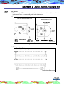
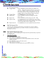
I.3
General Operation Guidelines
Alphanumeric Input When save a file that need key in alphanumeric,
this series is use the Edit Key. The first time pressing is number, the second
to fourth pressing each meaning follow the number key from left to right
side of the top capital, For example as below:
Key
1
Æ
1
Æ
1
Key Pressed LCD
1
1
2
1
3
Move
Confirmation
Test/Exit
Shift
Display
1
1
1A
1A
1AB
Click[←][↑][→][↓]to move cursor
Press [Enter]to confirm
Press [TEST]to start test,[Exit] to exit
Press [Shift] to launch alternative function
P7
CT-8700 User’s Guide
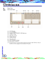
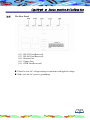
I.4
Tester Tour
I.4.A
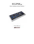
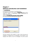
The Front Panel
(1)
(2)
(3)
(4)
(5)
(6)
(7)
(8)
(9)
(10)
(11)
P8
LCD Display
S1~S6 SoftKeys
PASS & FAIL & HIPOT LED Indicator
EditKey Group
MoveKey Group
Fastkey Group
SysKey Group
Power Switch
HV Calibration Output
Pin Search Connector
256 Pin Fixture Connector Slot (4 Slots are shown with 256 Pins. Only A
and B two slots equipped with standard 128 pins)
CHAPTER Ⅱ System Function & Configuration
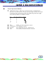
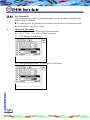
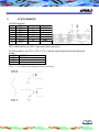
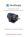
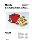
I.4.B
The points
(1) This series is 4 Wire measurement, it can test micro-resistance, but each test
point must have 2 connected point with instrument.
(2)
Traditional 2 Wire
4 Wire measurement test
measurement test
Error Source
Current Measurement
Source
Device
Under Test
Current
Source
Measurement
Device
Under Test
The 4 wire measurement greater the accuracy
(3) Wiring map
(3) Wiring map
under impedance test
P9
CT-8700 User’s Guide
(4) When change over from 4 wire to 2 wire measure mode, simply short 2 pins
together then connect to DUT.
(5) When the 4 wire circuit connect incorrect that will lead to the unforeseen
test result.
(6) Please use the fixture wiring function to test the fixture wiring whether
correct or not.
P 10
CHAPTER Ⅱ System Function & Configuration
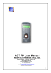
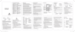
I.4.C
The Rear Panel
(12)
(13)
(14)
(15)
(16)
RS-232 Port(Reserved)
RS-485 Port(Reserved)
Remote Port
Printer Port
GPIB Port(Reserved)
Please be sure AC voltage setting is consistent with applied voltage.
Make sure the AC power is grounding.
P 11
CT-8700 User’s Guide
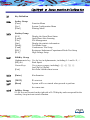
I.5
System Installation
Operation Procedure
(a) Be sour the AC input voltage selecter on the rear panel, power supply is set
to the proper position (AC 115 or 230V)
(b) Connect the converter and DUT cable
(c) Turn on the power the system will process self -test
(d) After self-test, LCD will display the READY SCREEN as below
Å Software Version
Å Current Time
(e) Press power switch to turn the system off if needed
The self-test will be conducted right after the system is turned on. It will take
60 80 seconds.
P 12
At the {READY} status, (Ready Screen display), Softkey S1 to S6 have the
following functions.
S1
Higher LCD contrast
S2
Lower LCD contrast
S5
Display current software version and time
S6
Select English/Chinese
CHAPTER Ⅱ System Function & Configuration
I.6
Key Definition
I.6.A
Syskey Group
[Func]
[Sys]
[Print]
Function Menu
System Configuration Menu
Printing Menu
Fastkey Group
[O/S]
[Learn]
[File]
[Stat]
[Mode]
[Cond]
[RLC]
[H.V.]
Display the Open/Short Status
Open/Short Auto Learning
File Management
Display the statistic information
Test Mode Setup
Conductance Test Setup
Resistance/Inductance/Capacitance/Diode Test Setup
High Voltage Setup
I.6.B
I.6.C
EditKey Group
Alphanumeric key Use for key in alphanumeric, including 0~1 and A~Z,./
[BS] (Å)
Back Space
Cursor Keys
Use to move cursors, including[←] [→] [↑] [↓]
And [PgUp] [PgDn]
[Exit]
Exit from current status/screen
I.6.D
[Enter]
Confirmation
I.6.E
[TEST]
To start test
I.6.F
[Reset]
System will be re-started when pressed to perform
the warm start.
I.6.G
SoftKey Group
S1~S6 keys are located on the right side of LCD display and correspond for the
auxiliary setup/activate/switch function.
P 13
CT-8700 User’s Guide
Chapter II
System Function and Configuration
System Function and Configuration, including Main Function .System
Configuration Setup and Printing Function, is described detail as following.
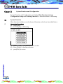
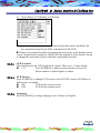
II.1
System Function
Main function includes several advanced functions, which are described below:
Operation Procedure
(a) Press[Func]
(b) LCD display as following
(c) Press [↑] or [↓] to select the item needed
(d) Press [Enter] to confirm selection
(e) press[Exit] to return
P 14
CHAPTER Ⅱ System Function & Configuration
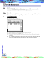
II.1.A
Selftest
The SELFTEST routine is to test the CPU, RAM, ROM, EEPROM, and
CLOCK.
Operation Procedure
(a) Press [Func]
(b) Press [↑] or [↓] to select the item and press[Enter]
(c) The program is running self-Test function
(d) LCD display as following
← Stop Self-Test
(e) Press [Exit] to return
P 15
CT-8700 User’s Guide
II.1.B
System Version information
This function provides the instrument information including Model/Test
Capability/Software Version/Edition/Released Date/ Total File Space and Free
File Space Operation Procedure
(a) Press [Func], useing [↑] or [↓] to select the item
(b) Press [Enter],LCD diplay as following
(c) From LCD display shows, you can get the Model/Test Capability/Software
Version/Edition/Released Date/Taotal File Space and Free File Space
P 16
CHAPTER Ⅱ System Function & Configuration
II.1.C
Meter Mode
This function including Conductance/RLC/Insulation/withstanding
Operation Procedure
(a) Press [Func]
(b) Using [↑] or [↓] to select the item
(c) LCD display as following
(d) Press [Enter] to get in to subordinate display of the Meter Mode
(e) LCD display as following
P 17
CT-8700 User’s Guide
II.1.C.a
Conductance
Operation Procedure
(a) Press [Func] using [↑] or [↓] to select the item
(b) Press [Enter], LCD display as following
(c) Press [↑] or [↓] to select (1) Conductance and press [Enter],
LCD display as following
(d) Press S1[PROG] to transform Port:A/B/C
(e) Press S6 [CAL.PIN], to run calibration pin. and press [Exit] to return
P 18
CHAPTER Ⅱ System Function & Configuration
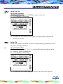
II.1.C.b
RLC
Operation Procedure
(a) The operation is the same with conductance, in the subordinate menu of
Meter Mode, using [↑] or [↓] to select (2) RLC item, LCD display as
following.
(b) Press [Enter] LCD display as following
(c) Press S1 [PROG] to shift FUNC:L/C/R/D 2.PORT:A/B/C 3.PIN±
(d) Press S3 [ZERO] meter offset (trimming)
Offest (trimming): the purpose of offset (trimming) is to eliminate the
effects of stray capacitance or series impedance in the connecting leads or
fixture.
(e) Press S4 [CLR.ZERO] clear the offest value
(f) Press S6 [CAL.PIN] to run the Calibration function
(g) After executed, press [Exit] to return to meter select menu
P 19
CT-8700 User’s Guide
II.1.C.c
Insulation
Operation Procedure
(a) The operation is the same with conductance, in the subordinate menu of
meter mode using [↑] or [↓] to select (3) Insulation, LCD display as
following
(b) Press [Enter] LCD display as following
(c) Press the S2 [ON/OFF] to turn ON/OFF the H/V output
(d) Press the S6 [CAL.PIN] to run calibration function
(e) Press the [Exit] to return to the meter select menu
P 20
CHAPTER Ⅱ System Function & Configuration
II.1.C.d
Withstanding
Operation Procedure
(a) The operation is the same conductance, in the subordinate menu of meter
mode using [↑] or [↓] to select (4) Withstanding, LCD display as
following:
(b) Press the [Enter] LCD display as following
(c) Press S3 [ON/OFF] to turn ON/OFF the H/V output
(d) Press S6 [CAL.PIN] to run Calibration function
(e) Press [Exit] to return to the meter select menu
P 21
CT-8700 User’s Guide
II.1.D
Calibration
Operation Procedure
(a) Press [Func]
(b) Use [↑] or [↓] to select the item
(c) Press [Enter] to enter to the subordinate mune of calibration mode
(d) LCD display as following
(e) Change this function will influence the accuracy of the instrument,
password is require for entering this page.
(f) Defult password is “8700”
P 22
CHAPTER Ⅱ System Function & Configuration
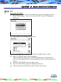
II.1.D.a
Open/Short Calibration
Operation Procedure
(a) Press [Func] and useing [↑] or [↓] to select Calibration
(b) Press [Enter] to enter to the subordinate mune of calibration mode
(c) LCD display as following
(d) Use [↑] or [↓] to select to (1) O/S Cal. And press [Enter]
(e) LCD display as following
P 23
CT-8700 User’s Guide
(f) Prsee S1[UP] or S2[DOWN] to adjust code
(g) After Setup finished, press S5 [DONE] to save or S6 [QUIT] to exit
without saving the setup
II.1.D.b
Conductance Calibration
Operation Procedure
(a) Opoeration the same O/S Cal. In the subordinate menu of calibration mode,
using [↑] or [↓] to select (2)Cond. Cal. Item, LCD display as following
(b) Press [Enter], LCD display as following
(c) Press S1[UP] or S2[DONT] to adjust code
(d) After setup finished, press S5 [DONE]
(e) If you want to abandon data, press S6[QUIT] to exit this screen
P 24
CHAPTER Ⅱ System Function & Configuration
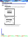
II.1.D.c
DC H//V Calibration
Operation Procedure
(a) Operation is the same before, in the subordinate mune of calibration mode,
using [↑] or [↓] to select (3) DC H/V Cal , LCD display as following
(b) Press [Enter], LCD display as following
(c) Press S1[UP] or S2 [DOWN] to adjust code, let the reading value match or
closer to the standard voltage as much as possiable
(d) Aslo you can press S4 [AUTO] adjust code automatically
(e) After setup finished, press S5 [DONE] to save
(f) If you want to abandon data, press S6[QUIT] to exit this screen
P 25
CT-8700 User’s Guide
II.1.D.d
AC H/V Calibration
Operation Procedure
(a) Operation is the same before, in the subordinate menu of calibration, use
[↑] or [↓] to select (4) AC H/V Cal. LCD display as following
(b) Press [Enter] LCD display as following
(c) Press S1 [UP] or S2[DOWN] to adjust code, let the reading value match or
closer to the standard voltage as much as possiable
(d) Also you can press S4[AUTO] to automatica setup code
(e) After setup finished, press S5[DONE] to save
(f) If you want to abandon data, press S6[QUIT] to exit from this screen
P 26
CHAPTER Ⅱ System Function & Configuration
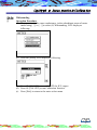
II.1.D.e
Insulation Calibration
Operation Procedure
(a) Operation is the same before, in the subordinate menu of calibration, using
[↑] or [↓] to select (5) Insu.Cal. LCD display as following
(b) Press [Enter], LCD display as following
(c) Press S1[UP] or S2[DOWN] to adjust code, let the reading value match or
closer to the standard voltage as much as possiable
(d) After setup finished, press S5 [DONE] to save
(e) If you want to abandon data, press S6[QUIT] to exit from this screen
P 27
CT-8700 User’s Guide
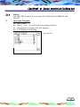
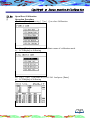
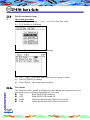
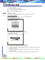
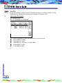
II.1.E
Pin Search
The function can automatic show the pin address contacted that we select
Operation Procedure
(a) Press [Func]
(b) Using [↑] or [↓] to select this item
(c) LCD display as following
(d) Press [Enter] to start search for pin
(e) Connect with Pin Search Probe, fixture or cable, instrument will automatic
detect pin location
(f) LCD display as following, the A08/A09/A10/A25 locations were detected
P 28
CHAPTER Ⅱ System Function & Configuration
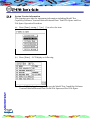
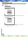
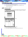
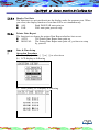
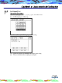
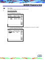
II.1.F
Fixture Wiring Circuit test
This function is to check whether the fixture has made a 4 wire connection. If
it shows OK that can be 4 wiring circuit, if NO that means wrong cable connect
or without contact.
Operation Procedure
(a) Press [Func] and using [↑] or [↓] to select this item
(b) Press [Enter] to start Fix. Wiring test, LCDdisplay as following
(c) Make sure the fixture has connected and there’s no any DUT(cable)
connected, then press [Enter]
(d) LCD display as following
P 29
CT-8700 User’s Guide
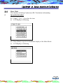
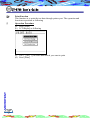
II.2
System setup
System Setup includes system configuration and test condition setup. The details
describe as following.
Operation Procedure
(a) Press [Sys]
(b) LCD display as following
(c) Using [↑] or [↓] to select item
(d) Press [Enter] to get in the indicate item to setup working
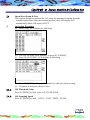
II.2.A
System Environments Setup
Operation Procedure
(a) Press [Sys]
(b) LCD display as following
(c) Using [↑] or [↓] to select (1)System Env. And press [Enter]
P 30
CHAPTER Ⅱ System Function & Configuration
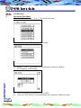
(d) LCD display as following
(e) Use [↑] or [↓] to select a setup item
(f) If need, press S1[PROG] to change, after setup finished, press [Enter]
(g) Complete setup, press [Exit] to leave
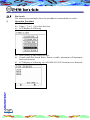
II.2.A.a
Power ON Self-Test
There are 2 selections, press S1[PROG] to shift, the pre-code is│ON│
YES
Power On Self-Test function is turn on
NO
Power On Self-Test function is turn off
II.2.A.b
Power Line Frequency
There are 2 selections, Press S1 [PROG] to shift, the pre-code is│60Hz│
50Hz
Power Line Frequency setup is 50Hz
60Hz
Power Line Frequency setup is 60Hz
II.2.A.c
Key stroke Sound
This instrument can follow requirement to shift key sound to be ON/OFF,
the pre-code is |ON|
ON
Sound performed when any key pressed
OFF
Sound do not performed when any key pressed
P 31
CT-8700 User’s Guide
II.2.A.d
Key Operation
This instrument provide key protection that to avoid any data be modified, the
default setup is |Unlock |
If want to select key protective or remove it which have to enter passwords,
the detail please read User’s Guide
Operation Procedure
(a) Press [Sys] to enter System Enviroement setup
(b) Use [↑] or [↓] to select (4)Key Operation
(c) LCD display as following
(d) Enter passwords xxxx,LCD display as following
P 32
CHAPTER Ⅱ System Function & Configuration
(e) Press [Enter], LCD display as following
(f)
Now the key protective has been removed and data can be modified, the
key operation setup from |LOCK | transform to|UNLOCK|.
Remove the protection mode if forgotten the passwords, in the display screen
{enter old passwords} and press [Shift]+[BS] the original will be shown, if want
to change the passwords, please read above operation procedure.
II.2.A.e
LCD Contrast
This function provide LCD bright level control, There are 1~8 steps totally.
1~8
Press S1[PROG] to adjust screen contrast, screen will
follow number to shift brighter or darker.
II.2.A.f
LCD Inverse
Press S1[PROG] to change LCD inverse to be ON/OFF, screen will follows to
shift inverse or normal.
ON
LCD shows inverse screen
OFF
LCD shows normal screen
II.2.A.g
Language
Press S1 [PROG] to change language to be Chinese or English
P 33
CT-8700 User’s Guide
II.2.B
Test Environment Setup
Operation procedure
(a) Press [Sys] and using [↑] or [↓] to select Test Env. item
(b) LCD display as following
(c) Press [Enter], LCD display as following
(d) Use [↑] or [↓] to select item which you are going to setup
(e) Press S1[PROG] to change
(f) Press [Enter] , after setup has been done
II.2.B.a
P 34
Test Alarm
The function is able /unable to alarm performed during the sequence test. You
can set the proper selection depending on your need.
ALL
Both PASS/FAIL sound on.
OFF
Both PASS/FAIL sound off.
PASS
Alarm performed only PASS test occurred.
FAIL
Alarm performed only FAIL test occurred.
CHAPTER Ⅱ System Function & Configuration
II.2.B.b
Display Test Data
The function is to activate/deactivate the display under the sequence test. When
you select, the display function of test data will be set simultaneously.
ALL
Both PASS/FAIL auto print on
FAIL
FAIL auto print process only
II.2.B.c
Printer Data Report
The function is to change the printer Data Report whether Auto or not.
AUTO
The Printer Data Report auto print on
MANUAL
The Printer Data Report auto print off, you have to setup
by yourself.
II.2.C
Date & Time Setup
Operation Procedure
(a) Press [Sys] and use [↑] or [↓] to select item
(b) LCD display as following
(c) Press [Enter], LCD display as following
P 35
CT-8700 User’s Guide
(d) Press S1[SET]
(e) Key in a exact date and time
(f) Complete it then press [Enter] to leave
Hour is 24-hours mode setting
II.2.D
Password Setup
You can set a system password to protect setting from revision.
Operation Procedure
(a) Press [Sys] and using [↑] or [↓] to select this item
(b) LCD display as following
(c) Press [Enter], LCD display as following
(d) Key in a initial password and press [Enter]
(e) Key in a new password and press [Enter]
(f) Key in new password again and press [Enter] to confirm, the screen will
display {success}
(g) When new password setup has been done the screen will return to the
selection menu
(h) Repeat (c)-(f) steps and input the proper password to protect data
P 36
CHAPTER Ⅱ System Function & Configuration
II.2.E
Set Output Port
Operation Procedure
(a) Press [Sys] and use [↑] or [↓] to select this item
(b) LCD display as following
(c) Press [Enter], LCD display as following
(d) Press S1[PROG] to change the output port setup
(e) This is to define the output port and pin
P 37
CT-8700 User’s Guide
II.3
Print Function
This function is to print the test data through printer port. The operation and
functions exposition as following
Operation Procedure
(a) Press [Print]
(b) LCD display as following
(c) Use [↑] or [↓] to select data which you want to print
(d) Press [Print]
P 38
CHAPTER Ⅱ System Function & Configuration
II.4
Open/Short Setup & Test
This system designs to perform the O/S setup by automatic learning from the
existed connections. After the learning process, the LCD display will
automatically show O/S status of DUT.
Operation Procedure
(a) Press [O/S], LCD display as following
(b) The O/S list come from learning, so press S3 [LEARN]
(c) Press S6 [O/S EDIT], LCD display as following
(d) Press S1[PROG] and key in alphanumeric what you want to setup
(e) Complete it and press [Exit] to leave
II.4.A
O/S Threshold Setup
Press S1 [PROG] to shift value in 2/5/10/20/50 kΩ
II.4.B
O/S Scanning Speed
Press S1 [PROG] to shift AUTO/FAST/MED/SLOW
P 39
CT-8700 User’s Guide
II.4.C
O/S End Detection
When run into the Open/Short whether to detect pins or not. If setup is NO that
speed would be faster, but do not detect the O/S end.
Press S1[PROG] to change setup to be YES/NO
II.4.D
Int. S/O Stop Mode
Press S1[PROG] to change setup to be AUTO/TIMER
AUTO:The system is repeatedly testing until the DUT cables completely
take off then stop automatically.
TIMER:To follow the test time doing test
II.4.E
Int. O/S Timer
Use alphanumeric to key in Int. O/S timer, but if mode setup is AUTO and this
setting will not work
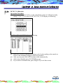
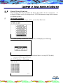
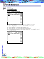
II.5
Statistic Report
You can view the statistics report by just press [Stat] key. The report includes
total test amounts, pass/fail amount and fail analysis in quantity/percentage.
Operation Procedure
(a) Press [Stat], LCD display as following
(b) Press S1[QTY.RATE] to display in percentage mode
P 40
CHAPTER Ⅱ System Function & Configuration
(c) LCDdisplay as following
(d) Press S4 [CLR] to clean the data of statistic
(e) Press [Exit] to leave
P 41
CT-8700 User’s Guide
Chapter III
Sequence Test Setup
Sequence test was designed by software programming to test DUT by multiple
test condition (setup) to complete the auto test in single routine by pressing just
one button. It saves time and effort effectively in mass production lines. It
includes three sessions.
III.1
Test Condition Setup
Run The Sequence Test
File Management
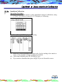
Test Condition Setup
Test conditions setup are defined to setup the test signals, control limits, and
necessary items before preceding the sequence test routine. That includes O/S /
Cond /RLC/HV …setup.
The signs of test parameter (Frequency, voltage and Current)
Control standard. specification standard and tolerate percentage
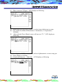
III.1.A
Open/ Short
Operation Procedure
(a) Press [O/S]
(b) LCD display as following
(c) Open/Short list is from learning
(d) Complete it then press [Exit] to leave
P 42
CHAPTER III Sequence Test Setup
III.1.B
Conductance Setup
Operation Procedure
(a) Press [Cond]
(b) LCD display as following
(c)
(d)
Use [↑] or[↓] to select the item needed
Complete setup, press [Exit] to leave
High limit
use number key to enter value, the limit is 0~50Ω
Low limit
use number key to enter value, the limit is 0~50Ω
Test Speed
Press S1[PROG] to shift speed as
FAST/LOWER/FMID/AUTO
When setting is AUTO, the system will automatically
select fastest and steadiest test speed to progress
Int. Limit Spec
Use numeric key to enter value, the limit is ±50Ω
This function provides the repeatedly test at one DUT
Int. Stop Mode
Use S1 [PROG] to change mode be AUTO/TIMER
AUTO: System will test repeated until DUT cable
completely take off then automatic stop
TIMER: Follow test time to do test
Int. timer
Use alphanumeric key to setup second, the limit is 0~99,
However, when the Int. stop mode setting is auto, this
function will not work.
P 43
CT-8700 User’s Guide
III.1.C
R/L/C Setup
Operation Procedure
(a) Press [RLC]
(b) LCD display as following
(c)
(d)
(e)
(f)
(g)
Use S1 [HOME] move cursor to the first of R/L/C setup data.
Press S2 [END] move cursor to the end of R/L/C setup data
Press S4 [COPY] to copy a data from last row
Press S6 [DEL.] to delete a data which you seleced
Use alphanumeric keys to enter a name for the file. For example, enter 1
for the first data
(h) Press [Enter] to confirm
P 44
CHAPTER III Sequence Test Setup
(i)
Move cursor to T(Type),LCD display as following
(j) Press S1[R ]/S2 [L]/S3[C ]/S4[D ] to select item which want to setup
(k) The symbol as follow:R-Resistance, L-Inductance, C-Capacitance,
D-Diode
(l) After selected, Press [Enter] cursor will move to ”P+”, LCD display as
following
(m) Use S1[A] or S2[B] to select A/B, and use alphanumeric to enter setup pin
(n) Press [Enter] to confirm
(o) Cursor will move to “Std-Val", LCD display as following
P 45
CT-8700 User’s Guide
(p) In this item, use the alphanumeric to setup stand value as weel
(q) After, useS1[Ω]/S2[KΩ]/S3[MΩ] to select a unit of Std-Val unit
(r) Press[Enter] to confirm, cursor will move to “Tol%” display as following
(s) Use alphanumeric to setup tolerate
(t) Use S1[>=STD]/S2[<=STD]/S6[ALL SAME] to shift tolerate setup
(u) Following this way to setup test condition what you needed, LCD display
as following
(v) Press [ Enter ] to confirm, LCD display as following
(w) Complete it then press [ Exit] to leave
P 46
CHAPTER III Sequence Test Setup
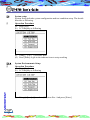
III.1.D
Test Mode Edit
Test Mode Setup is to set the related action during the sequence test routine.
Operation Procedure
(a) Press [Mode]
(b) LCD display as following
(c) Use [↑] or [↓] to move cursor to the item you want to setup
(d) Use alphanumeric to enter setup value, or press S1[PROG] to change
setup of the test items.
(e) Press S6 [PARA] to select item which you want to test
(f) Press S6 [PARA], LCD display as following
(g) Use [↑] or [↓] to move cursor to an item which you want to setup
(h) Press S1[PROG] to change that item whether process test or not
P 47
CT-8700 User’s Guide
(i)
The Items Exposition
Trigger Mode
Press S1[PROG] to shift setting to be MANUAL/
AUTO. When this function is ON, the system will
scan cable whether connect with fixture or not. If so,
the system will start testing automatically, when the
setting is OFF, you can only use [Test] to start test.
Trigger Delay
Use alphanumeric to enter delay times.
Break Point
Press S1[PROG] to shift test setting to be OFF/
O/S/L/V.
Repeat Test
Press S1[PROG] to shift setting to be ON/OFF.
Repeat Count
Use alphanumeric to enter repeated test count. When
the setting is ON, the test count setting is 0, the system
will test repeatedly until run against a fail.
Repeat interval
Use alphanumeric to enter repeated test interval time.
III.2
Run The Sequence Test
After the setup completion of all items you needed, the system is ready to
proceed and run the sequence test routine. For the two occasions will occur
description as below:
III.2.A
Run The Real Time Sequence Test
This routine is called in applying the setups stored in system memory to process
the sequence test.
Operation Procedure
(a) Check out all of test setup
(b) Press [Mode] will display test mode setup
(c) Check out and confirm the test mode setup whether correct or not, and
modify if needed.
(d) Press [EXIT] to return to the main screen
(e) Press [TEST] to start test
(f) When finish or need discontinue test, press [EXIT] to leave.
P 48
CHAPTER III Sequence Test Setup
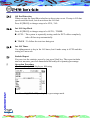
III.2.B
Run The Existed Sequence Test
You can load existed file from storage memory to main memory to run the
sequence test routine.
Operation Procedure
(a) Press[File]
(b) Use [↑] or [↓] to move cursor to the file you needed
(c) Press [Enter] to confirm selection and call the file load routine
(d) LCD will return to main screen and the file shows that file name you have
selected
(e) Press [EXIT]to return to main screen
(f) Press [Mode] display the test mode setup screen
(g) Check out all test setup previously before saving
(h) Press [EXIT] to return to main screen
(i) Press [TEST] and start testing
(j) Press [EXIT] to leave when the test finish or discontinue
P 49
CT-8700 User’s Guide
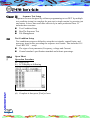
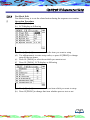
III.3
File Management
You can call the Load; Sort or Del routines to proceed file management for
running the EXISTED SEQUENCE TEST implementation:
III.3.A
Open File
Open File is to load a file in storage memory to main memory, which completes
the preparation for the running of sequence test.
Operation Procedure
(a) Press[File]
(b) LCD display as following
(c) Use [↑] or [↓] move cursor to the item you needed
(d) Press [Enter] to start loading file
(e) The tester start to load file from those files have been selected into main
memory.
(f) LCD display will return to main screen, the present file will show the files
name as you have selected, now then, the files load are completive.
P 50
CHAPTER III Sequence Test Setup
III.3.B
Open New File
Operation Procedure
(a) Press [File], and press S1[NEW] to open an new file
(b) LCD display as following
(c) Enter an name for new file
(d) Confirm the file which you are going to setup and press [Enter] the
file has been done.
III.3.C
Delete File
Delete File routine is to delete the file in storage memory parentally to save
the space of storage memory.
Operation Procedure
(a) Press [File] and use [↑] or [↓] to select the item you want to delete.
(b) Press S3 [DEL.] to delete file
(c) LCD display as following
(d) Confirm the file’s name and press [Enter], the file will be deleted.
P 51
CT-8700 User’s Guide
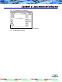
III.3.D
Sort File
Save File routine is to save the file in main memory to storage memory for the
application of editing, monitoring, and running of sequence test.
Operation Procedure
(a) Press [File]
(b) LCD display as following
(c)
P 52
Press S5[SORT] to sort files depend on your selection
Descending by name
Ascending by name
Ascending by sequence of stored date
Descending by date
Ascending by date
CHAPTER III Sequence Test Setup
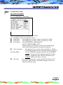
III.4
View Mode
This function display the mode of the files record
Operation Procedure
(a) Press [File]
(b) LCD display as following
(c) Use S6[VIEW MODE] to shift files management screen to be simple
sort files, display as following.
P 53
CT-8700 User’s Guide
APPENDIX
1.
A、
CT-8700 Cable sets
RS-232C CABLE
9-PIN connector (Female)
NC
RxD
TxD
DSR
GND
CTS
CTS
RTS
GND
2.
1
2
3
4
5
6
7
8
9
25-PIN connector (Female)
1
2
3
4
5
6
7
20
PRINTER CABLE
25-PIN
connector
(Male)
1
2
3
4
5
6
7
8
9
10
11
13
18 ~ 25
P 54
36-PIN
connector
(Male)
1
2
3
4
5
6
7
8
9
10
11
13
19 ~ 30, 33
Symbol
STROBE
DATA 0
DATA 1
DATA 2
DATA 3
DATA 4
DATA 5
DATA 6
DATA 7
ACKNLG
BUSY
SLCT
GND
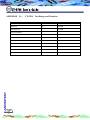
APPENDIX
3.
CT-8700 REMOTE
15-PIN Connector
1
CTL0
2
CTL1
3
CTL2
4
CTL3
5
CTL4
6
CTL5
7
CTL6
8
CTL7
9
10
11
12
13
14
15
IPC∅
GND
IPC∅+GND define as [TEST ] input (short these two pins )
On testing status, the CTL 0, CTL 2, CTL 3, are the output signal which are defined as
bellow:
CTL0
“PASS” status
CTL1
”FAIL” status
CTL2
CTL3
CTL0 ~ CTL1 Inside circuit diagram listed as following
P 55
CT-8700 User’s Guide
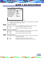
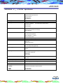
APPENDIX
B、
CT-8700
Test Range and Function
ITEM
SYMBOL
TEST RANGE
Open/Short
O/S
1Ω~50KΩ
Intermittent O/S
1Ω~50KΩ
O/S End judgement
Conductance
COND
Intermittent Cond.
Max. 50.0Ω
Max. 50.0Ω
Resistance
R
Max. 10.0MΩ
Capacitance
C
10pF~1µF
Zener
Zener
0~8V
Insulation
IR
0.1MΩ~1.5GΩ
Hipot
Hipot
Max. 5mA
P 56
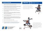
APPENDIX
APPENDIX
C、
CT-8700
Specification
Advanced Functions
4-Wire Measurement
Programmable Sequential Test
Auto Pin Search
Self Diagnostic
Self Calibration
Scanning Mode
Auto/Short Switchable
Test Single Information
Output Rating: 5Vdc
DC Hiport / Insulation
50V Resolution
±1% Accuracy
50~1000Vdc/50~1000Vac(/FA)
Display and Sound
320 x 240 Graphic LCD Display
Pass/Fail LED Indicator/LCD Display
Internal Speaker
Connections
64 Test Points
128 Test Points (Optional)
Hipot Calibration +/- Output
Auto Pin Search Jack
Front Panel Control Buttons
Syskey / Fastkey / Editkey
I/O Interface
RS-232 Port
Printer Port
Remote Control Port
Memory
56 Setup Files
Max. 120 Setup Files (Optional)
Power Supply
115/230Vac ± 10% Switchable
60/50Hz
Accessory
Remote Control Cable (Optional)
RS-232 Cable (Optional)
Power Cord
User's Guide
Temperature & Humidity
15ºC~35ºC
RH≦75%
Dimension (WxHxD)
425 x 190 x 350mm
Weight
Approx, 15kgs (w/o Accessory)
Cable Capacitance Limit
1µF Max.
Ordering Information
CT-8700
4- Wire Universal Cable / Harness Tester
/128P
/256P
128 Test Points
256 Test Points
P 57