1
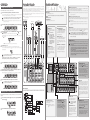
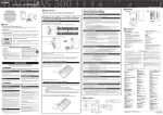
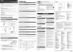
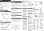
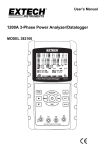
•
Powered mixer
• The
powered mixer is a convenient, high-performance all-in-one unit that includes EQ and reverb. With four
monaural inputs and three stereo inputs, the STAGEPAS 500 can be connected to a wide range of
instruments and devices.
The STAGEPAS 500 can be used in even the most cramped quarters, inside or outside, since the mixer is
built into one of the speaker cabinets. The other speaker has a special compartment for storing speaker
cables and microphones, letting you put all you need for your performance in one convenient place.
Two speakers (500S), mixer, panel, power cord, two speaker cables, Owner’s Manual (this booklet)
NOTE:
The mixer and the panel are installed in the speakers when the STAGEPAS 500 leaves the factory.
• Are the SPEAKERS L/R jacks connected to the included speakers (500S)?
• Are the included speaker cables used?
1
Read these instructions.
2
Keep these instructions.
3
Heed all warnings.
4
Follow all instructions.
5
Do not use this apparatus near water.
Do not block any ventilation openings. Install in accordance with the
manufacturer's instructions.
8
Do not install near any heat sources such as radiators, heat registers, stoves, or
other apparatus (including amplifiers) that produce heat.
9
Do not defeat the safety purpose of the polarized or grounding-type plug. A
polarized plug has two blades with one wider than the other. A grounding type
plug has two blades and a third grounding prong. The wide blade or the third
prong are provided for your safety. If the provided plug does not fit into your
outlet, consult an electrician for replacement of the obsolete outlet.
• Are the LEVEL controls of all relevant channels and/or the MASTER LEVEL control set to appropriate levels?
WARNING
Power supply/Power cord
• Only use the voltage specified as correct for the device. The required
voltage is printed on the name plate of the device.
). Compression may be effective in
• Do not place the power cord near heat sources such as heaters or
radiators, and do not excessively bend or otherwise damage the cord,
place heavy objects on it, or place it in a position where anyone could
walk on, trip over, or roll anything over it.
• Are the LEVEL controls of all relevant channels and/or the MASTER LEVEL control set to appropriate levels?
• Be sure to connect to an appropriate outlet with a protective grounding
connection. Improper grounding can result in electrical shock.
Do not open
• Do not open the device or attempt to disassemble the internal parts or
modify them in any way. The device contains no user-serviceable parts.
If it should appear to be malfunctioning, discontinue use immediately and
have it inspected by qualified Yamaha service personnel.
• Are both XLR type and phone type jacks on channels 1–4 being used (connected) at the same time?
• Is the input signal from the connected device set to an appropriate level?
Securely hold the mixer’s handles to remove it from the speaker.
Water warning
• Do not expose the device to rain, use it near water or in damp or wet
conditions, or place containers on it containing liquids which might spill
into any openings.
• Never insert or remove an electric plug with wet hands.
• Are the REVERB switches of each channels set to ON (
• Is the REVERB control set to an appropriate level?
Power supply/Power cord
• Remove the electric plug from the outlet when the device is not to be used
for extended periods of time, or during electrical storms.
Changing the sound quality
• When removing the electric plug from the device or an outlet, always hold
the plug itself and not the cord. Pulling by the cord can damage it.
• Are the Equalizer controls (HIGH/LOW) set to appropriate levels?
• If you want to get a more powerful sound from the speakers, set the SPEECH/MUSIC switch to MUSIC (
• If you want to get a clearer sound for announcements, set the SPEECH/MUSIC switch to SPEECH (
).
).
Using a single speaker
• You can use a single speaker. If you use a single speaker, the mixer outputs just one channel of the stereo
Use only the mixer's handles when removing the mixer from the speaker and when carrying the mixer
Caution
NOTE:
signal, left or right.
separate from the speaker.
The mixer can also be used when installed in the speaker.
When you install the mixer into the speaker, make sure to match the indentations on the speaker cabinet to
the corresponding parts on the mixer, and then turn each screw from OPEN to LOCK until it clicks.
Outputting the signal for monitoring
• Connect a powered speaker to the MONITOR OUT jack. The MONITOR OUT jack outputs the signal prior
to routing through the MASTER LEVEL control. Adjust the level of output signal from the MONITOR OUT
jack with the MONITOR OUT control. The MONITOR OUT control does not affect the MASTER LEVEL
control. If only the L (left) MONITOR OUT jack is used, the mixer mixes the left and right signals and sends
Turning the power on/off
1
2
Be sure that the mixer’s power switch is turned off.
them to the jack.
Connect the included power cord to the [AC IN] jack, and plug the power
cord into a power outlet.
• When transporting or moving the device, always use two or more people.
Attempting to lift the device by yourself may damage your back, result in
other injury, or cause damage to the device itself.
• Before moving the device, remove all connected cables.
• When setting up the device, make sure that the AC outlet you are using is
easily accessible. If some trouble or malfunction occurs, immediately turn
off the power switch and disconnect the plug from the outlet.
• Do not use the device in a confined, poorly-ventilated location. Make sure
that there is adequate space between the mixer and surrounding walls or
other devices: at least 30 cm at the sides, 30 cm behind and 30 cm
above. If the mixer is to be used installed into the speaker cabinet, make
sure to allow adequate space between the speaker and the surrounding
walls or other devices: at least 30 cm at the sides, 30 cm behind and 30
cm above. Inadequate ventilation can result in overheating, possibly
causing damage to the device(s), or even fire.
• Avoid setting all equalizer controls and faders to their maximum.
Depending on the condition of the connected devices, doing so may
cause feedback and may damage the speakers.
• Do not expose the device to excessive dust or vibrations, or extreme cold
or heat (such as in direct sunlight, near a heater, or in a car during the
day) to prevent the possibility of panel disfiguration or damage to the
internal components.
• Do not place the device in an unstable position where it might
accidentally fall over.
• Do not block the vents. This mixer has ventilation holes at the top to
prevent the internal temperature from becoming too high. In particular, do
not place the device on its side or upside down. Inadequate ventilation
can result in overheating, possibly causing damage to the device(s), or
even fire.
• To avoid any loud, unexpected noise from the speakers, first turn on the power to those connected devices
Caution
• Do not use the device in the vicinity of a TV, radio, stereo equipment,
mobile phone, or other electric devices. Doing so may result in noise,
both in the device itself and in the TV or radio next to it.
that are closest to the sound source.
Example: Sound source (CD player or instrument) → STAGEPAS 500
When turning off the power to the system, reverse the order described above.
• Before turning on the power, set the LEVEL controls and MASTER LEVEL control to their minimum setting (zero).
3
Press the mixer’s power switch to the ON position.
The POWER indicator lights.
To turn the power off, press the power switch to the OFF position.
The POWER indicator turns off.
Connections
The STAGEPAS 500 features a convenient storage compartment in the speaker box for packing the included
power cable, speaker cable, Owner’s Manual (this booklet), and an optional microphone and the cable, as
shown above. Remove the rear panel of the speaker and put in the things you need. Carry the STAGEPAS
500 with you, and you’ve got all you need to set up and perform—anywhere, anytime.
+15
10
9/10
10 0
7/8
10 0
5/6
10 0
4
10 0
330.0
3
10 0
2
10 0
+15
0
-6
-20
10
POWER
SPEECH
MUSIC
+6
+3
1
LEVEL
LOW
+15 –15
+15 –15
LEVEL
LOW
+15 –15
+15 –15
LEVEL
LOW
+15 –15
+15 –15
LEVEL
LOW
+15 –15
+15 –15
REVERB
LEVEL
LOW
+15 –15
+15 –15
REVERB
LEVEL
LOW
+15 –15
+15 –15
REVERB
LEVEL
–15
–15
REVERB
LOW
0
10
0
10
REVERB
LEVEL
L
R
HIGH
R
R
HIGH
MIC
LINE
HIGH
LIMIT
COMP
HIGH
HIGH
LIMIT
COMP
MIC
LINE
(MONO)
R
L
ON
OFF
MONITOR
OUT
PHANTOM
LIMIT/COMP switch
ON = Comp, OFF = Limit (CH1/2)
Maximum Output Power
250 W + 250 W (±10 %)/4Ω @ 10 % THD at 1 kHz (SPEAKERS L/R)
200 W + 200 W/4Ω @ 1 % THD at 1 kHz (SPEAKERS L/R)
Power Consumption
65 W
Weight
24 kg (Speaker x 2 + Powered Mixer)
Total Harmonic Distortion
0.5 % @ 20 Hz, 1 kHz, 20 kHz +14 dBu GAIN= nominal (MONITOR OUT, REC OUT)
Hum & Noise (Equivalent Input Noise, Rs = 150Ω, MIC/LINE = MIC)
-106 dBu (CH1/2)
-112 dBu (CH3/4)
-65 dBu Residual output noise (SPEAKERS L/R)
Stereo Input Channel Equalization
±15 dB
HIGH 10 kHz shelving
LOW 100 Hz shelving
n Speakers (500S)
Enclosure
2 way bass-reflex type, Polypropylene, Black
Crossover Frequency
4.0 kHz (LF: 12 dB/oct, HF: 12 dB/oct)
Frequency Range
55 Hz-20 kHz (-10 dB)
Crosstalk (1 kHz)
-70 dB between input channels
Speaker Unit
LF: 10" (25 cm) Cone
HF: 1" (2.54cm) Compression Driver
• If this device should be dropped or damaged, immediately turn off the
power switch, disconnect the electric plug from the outlet, and have the
device inspected by qualified Yamaha service personnel.
FCC INFORMATION (U.S.A.)
1.
IMPORTANT NOTICE: DO NOT MODIFY THIS UNIT!This product, when installed as
indicated in the instructions contained in this manual, meets FCC requirements.
Modifications not expressly approved by Yamaha may void your authority, granted by
the FCC, to use the product.
2.
IMPORTANT: When connecting this product to accessories and/or another product
use only high quality shielded cables. Cable/s supplied with this product MUST be
used. Follow all installation instructions. Failure to follow instructions could void your
FCC authorization to use this product in the USA.
3.
NOTE: This product has been tested and found to comply with the requirements listed
in FCC Regulations, Part 15 for Class "B" digital devices. Compliance with these
requirements provides a reasonable level of assurance that your use of this product in
a residential environment will not result in harmful interference with other electronic
devices. This equipment generates/uses radio frequencies and, if not installed and
used according to the instructions found in the users manual, may cause interference
harmful to the operation of other electronic devices. Compliance with FCC regulations
does not guarantee that interference will not occur in all installations. If this product is
found to be the source of interference, which can be determined by turning the unit
"OFF" and "ON", please try to eliminate the problem by using one of the following
measures:Relocate either this product or the device that is being affected by the
interference.
Utilize power outlets that are on different branch (circuit breaker or fuse) circuits or
install AC line filter/s.
In the case of radio or TV interference, relocate/reorient the antenna. If the antenna
lead-in is 300 ohm ribbon lead, change the lead-in to co-axial type cable.
If these corrective measures do not produce satisfactory results, please contact the
local retailer authorized to distribute this type of product. If you can not locate the
appropriate retailer, please contact Yamaha Corporation of America, Electronic Service
Division, 6600 Orangethorpe Ave, Buena Park, CA90620
The above statements apply ONLY to those products distributed by Yamaha
Corporation of America or its subsidiaries.
* This applies only to products distributed by YAMAHA CORPORATION OF AMERICA.
Handling caution
• When turning on the AC power in your audio system, always turn on the
device LAST, to avoid speaker damage. When turning the power off, the
device should be turned off FIRST for the same reason.
• Do not insert your fingers or hands in any gaps or openings on the device
(vents,, ports, etc.).
(class B)
IMPORTANT NOTICE FOR THE UNITED KINGDOM
Connecting the Plug and Cord
WARNING: THIS APPARATUS MUST BE EARTHED
IMPORTANT. The wires in this mains lead are coloured in accordance with the following
code:
GREEN-AND-YELLOW : EARTH
BLUE
: NEUTRAL
BROWN
: LIVE
As the colours of the wires in the mains lead of this apparatus may not correspond with the
coloured markings identifying the terminals in your plug proceed as follows:
The wire which is coloured GREEN-and-YELLOW must be connected to the terminal in the plug
which is marked by the letter E or by the safety earth symbol
or colored GREEN or
GREEN-and-YELLOW.
The wire which is coloured BLUE must be connected to the terminal which is marked with the
letter N or coloured BLACK.
The wire which is coloured BROWN must be connected to the terminal which is marked with the
letter L or coloured RED.
• This applies only to products distributed by Yamaha Music U.K. Ltd.
(3 wires)
For details of products, please contact your nearest Yamaha representative or the authorized distributor listed below.
Location
• Do not use the speaker's handles for suspended installation. Doing so
can result in damage or injury.
Convenient built-in storage compartment
n General Specifications
If you notice any abnormality
• If the power cord or plug becomes frayed or damaged, or if there is a
sudden loss of sound during use of the device, or if any unusual smells
or smoke should appear to be caused by it, immediately turn off the
power switch, disconnect the electric plug from the outlet, and have the
device inspected by qualified Yamaha service personnel.
Always follow the basic precautions listed below to avoid the possibility of physical injury to you or others, or damage
to the device or other property. These precautions include, but are not limited to, the following:
)?
Specifications and descriptions in this owner's manual are for information purposes only. Yamaha Corp. reserves the right to change or modify products or specifications at
any time without prior notice. Since specifications, equipment or options may not be the same in every locale, please check with your Yamaha dealer.
Phantom Voltage
+15 V (CH1-4)
CAUTION
Reverb is not applied to the sound
Specifications
Frequency Response (Nomimal output level @ 1 kHz)
-3 dB, 0 dB, +1 dB @ 20 Hz-20 kHz (MUSIC/SPEECH=MUSIC) (MONITOR OUT)
-3 dB, 0 dB, +1 dB @ 80 Hz-20 kHz (MUSIC/SPEECH = SPEECH) (REC OUT)
-3dB, 0dB, +1 dB @ 20 Hz-20 kHz, 1 W Output (MUSIC/SPEECH=MUSIC, without Speaker
EQ) (SPEAKERS L/R)
• Is the PHANTOM switch set to ON when using a condenser microphone?
3
* Use of the stand should refer to stand manufacturer's instructions.
Maximum Output Level
116 dB (1 m)
Always follow the basic precautions listed below to avoid the possibility of serious injury or even death from electrical
shock, short-circuiting, damages, fire or other hazards. These precautions include, but are not limited to, the following:
• Are the MIC/LINE switches of each channels set appropriately?
OPEN
CH1-4
Tripod pole diameter 35-36
* Please keep this manual in a safe place for future reference.
Sound is distorted or noise is produced
LOCK
OPEN
120
2-M8 x 25
PLEASE READ CAREFULLY BEFORE PROCEEDING
Please connect to only one of these jacks on each channel.
LOCK
L
14 Refer all servicing to qualified service personnel. Servicing is required when the
apparatus has been damaged in any way, such as power-supply cord or plug is
damaged, liquid has been spilled or objects have fallen into the apparatus, the
apparatus has been exposed to rain or moisture, does not operate normally, or
has been dropped.
PRECAUTIONS
LOCK
OPEN
298
342
13 Unplug this apparatus during lightning storms or when unused
for long periods of time.
TO REDUCE THE RISK OF FIRE OR ELECTRIC SHOCK, DO NOT EXPOSE THIS APPARATUS TO RAIN OR MOISTURE.
• Use only the included power cord.
OPEN
HIGH
L
Clean only with dry cloth.
7
111.5
175
faulty. Check that the speaker cable is correctly connected to the mixer and reapply the power.
• Use channels 1 or 2, and set the LIMIT/COMP switches to COMP (
LOCK
R
L (MONO)
6
• Is the POWER indicator flashing? There may be a short in the speaker cable or the connection may be
• Is the input signal from the connected device set to an appropriate level?
OPEN
ON
AC IN
12 Use only with the cart, stand, tripod, bracket, or table specified
by the manufacturer, or sold with the apparatus. When a cart is
used, use caution when moving the cart/apparatus combination
to avoid injury from tip-over.
(98-6500)
Please connect to only one of these jacks on each channel.
LOCK
POWER
OFF
11 Only use attachments/accessories specified by the manufacturer.
Use only the speaker cables included with the device.
Sound is not loud enough
MIC
LINE
10 Protect the power cord from being walked on or pinched particularly at plugs,
convenience receptacles, and the point where they exit from the apparatus.
WARNING
If the connector of a speaker cable other than the included speaker cable touches any metal parts such as
Use a screwdriver or coin to turn each screw on the mixer from LOCK to
OPEN until it clicks.
HIGH
MIC
LINE
• Are the LEVEL controls of all relevant channels and/or the MASTER LEVEL control set to appropriate levels?
preventing distortion.
MONITOR
OUT
L
• Are external instruments (including a microphone) or speakers correctly connected to the mixer?
Be sure that the mixer’s power switch is turned off.
R
L
• Is the LIMITER flashes continuously? If the internal power amplifier section is excessively overloaded, the
• Are both XLR type and phone type jacks on channels 1–4 being used (connected) at the same time?
Remove the mixer
OPEN
LIMITER
SPEAKERS
mixer, the power may be turned off automatically and the mixer may reset itself.
• Are the MIC/LINE switches of each channels set appropriately?
Before turning on the mixer
1
2
IMPORTANT SAFETY INSTRUCTIONS
• Is the vent on the top panel of the mixer blocked? Since inadequate ventilation can result in overheating the
• If sound is not still output, contact your Yamaha dealer.
Package Contents
LOCK
OPEN
the mixer's handle, no sound may result because of a short circuit.
• Convenient storage
n Mixer
LOCK
No sound is heard
Two-way, 10-inch (25 cm) speaker system
The built-in speakers deliver high-quality powerful sound from an exceptionally compact cabinet.
The scratch-resistant speakers are rugged enough for outdoor use.
n Speaker
The exclamation point within an equilateral triangle is intended to alert the user to the presence of important
operating and maintenance (servicing) instructions in the literature accompanying the product.
The above warning is located on the bottom
of the mixer and the rear of the speakers.
power may be turned off automatically and the mixer may reset itself.
Features
Unit: mm
0
CAUTION: TO REDUCE THE RISK OF
ELECTRIC SHOCK, DO NOT REMOVE
COVER (OR BACK). NO USER-SERVICEABLE
PARTS INSIDE. REFER SERVICING TO
QUALIFIED SERVICE PERSONNEL.
Power shuts down suddenly
Thank you for your purchase of the Yamaha PORTABLE PA SYSTEM STAGEPAS 500. The STAGEPAS 500 is a
versatile, compact PA system consisting of two speakers and a mixer.
In order to get the most out of your new STAGEPAS 500 and its sophisticated functions, we suggest you read
through this manual thoroughly. Also keep it in a safe place for future reference.
Dimensions
The lightning flash with arrowhead symbol within an equilateral triangle is intended to alert the user to the
presence of uninsulated "dangerous voltage" within the product's enclosure that may be of sufficient
magnitude to constitute a risk of electric shock to persons.
0
Power does not turn on
• Is the included power cord correctly connected to a power outlet?
Introduction
Explanation of Graphical Symbols
MASTER
C AU TI ON
RISK OF ELECTRIC SHOCK
DO NOT OPEN
R
Owner’s Manual
Troubleshooting
544.5
500
152
EN
• Before connecting the device to other devices, turn off the power for all
devices. Before turning the power on or off for all devices, set all volume
levels to minimum.
• For the SPEAKERS jacks, Use only the included speakers (500S) and
speaker cables. Use of other types of speakers and cables may result in
damage to the device(s), or even fire.
• Avoid inserting or dropping foreign objects (paper, plastic, metal, etc.)
into any gaps or openings on the device (vents, ports, etc.) If this
happens, turn off the power immediately and unplug the power cord from
the AC outlet. Then have the device inspected by qualified Yamaha
service personnel.
• Do not use the device for a long period of time at a high or uncomfortable
volume level, since this can cause permanent hearing loss. If you
experience any hearing loss or ringing in the ears, consult a physician.
• Do not operate the device if the sound is distorting. Prolonged use in this
condition could cause overheating and result in fire.
• Do not rest your weight on the device or place heavy objects on it, and
avoid use excessive force on the buttons, switches or connectors.
NORTH AMERICA
CANADA
Yamaha Canada Music Ltd.
135 Milner Avenue, Scarborough, Ontario,
M1S 3R1, Canada
Tel: 416-298-1311
U.S.A.
Yamaha Corporation of America
6600 Orangethorpe Ave., Buena Park, Calif. 90620,
U.S.A.
Tel: 714-522-9011
CENTRAL & SOUTH AMERICA
MEXICO
Yamaha de México S.A. de C.V.
Calz. Javier Rojo Gómez #1149,
Col. Guadalupe del Moral
C.P. 09300, México, D.F., México
Tel: 55-5804-0600
All full-range loudspeakers are fitted with a self-resetting poly switch that
protects the high-frequency driver from damage caused by excessive
power. If a loudspeaker cabinet loses high-frequency output, immediately
remove power from the unit and wait for two to three minutes. This should
be long enough to allow the poly switch to reset. Reapply power and check
the performance of the high frequency driver before continuing, with the
power reduced to a level that does not cause the poly switch to interrupt
the signal.
Interference From Cell Phones
Using a cell phone near the speaker system can induce noise. If this occurs,
move the cell phone further away from the speaker system.
Yamaha Musical do Brasil Ltda.
Rua Joaquim Floriano, 913 - 4' andar, Itaim Bibi,
CEP 04534-013 Sao Paulo, SP. BRAZIL
Tel: 011-3704-1377
THE NETHERLANDS/
BELGIUM/LUXEMBOURG
Yamaha Music Europe Branch Benelux
Clarissenhof 5-b, 4133 AB Vianen, The Netherlands
Tel: 0347-358 040
FRANCE
Yamaha Musique France
BP 70-77312 Marne-la-Vallée Cedex 2, France
Tel: 01-64-61-4000
ITALY
Yamaha Musica Italia S.P.A.
Combo Division
Viale Italia 88, 20020 Lainate (Milano), Italy
Tel: 02-935-771
Yamaha Música Ibérica, S.A.
Ctra. de la Coruna km. 17, 200, 28230
Las Rozas (Madrid), Spain
Tel: 91-639-8888
SWEDEN
ARGENTINA
Yamaha Music Latin America, S.A.
Sucursal de Argentina
Olga Cossettini 1553, Piso 4 Norte
Madero Este-C1107CEK
Buenos Aires, Argentina
Tel: 011-4119-7000
PANAMA AND OTHER LATIN
AMERICAN COUNTRIES/
CARIBBEAN COUNTRIES
Yamaha Music Latin America, S.A.
Torre Banco General, Piso 7, Urbanización Marbella,
Calle 47 y Aquilino de la Guardia,
Ciudad de Panamá, Panamá
Tel: +507-269-5311
EUROPE
THE UNITED KINGDOM
Air blowing out of the bass reflex ports is normal, and often occurs when the
speaker is handling program material with heavy bass content.
Yamaha Music U.K. Ltd.
Sherbourne Drive, Tilbrook, Milton Keynes,
MK7 8BL, England
Tel: 01908-366700
Yamaha Scandinavia AB
J. A. Wettergrens Gata 1, Box 30053
S-400 43 Göteborg, Sweden
Tel: 031 89 34 00
DENMARK
YS Copenhagen Liaison Office
Generatorvej 6A, DK-2730 Herlev, Denmark
Tel: 44 92 49 00
NORWAY
Norsk filial av Yamaha Scandinavia AB
Grini Næringspark 1, N-1345 Østerås, Norway
Tel: 67 16 77 70
RUSSIA
Yamaha Music Europe GmbH
Siemensstrasse 22-34, 25462 Rellingen, Germany
Tel: 04101-3030
SWITZERLAND/LIECHTENSTEIN
Yamaha Music Europe GmbH
Branch Switzerland in Zürich
Seefeldstrasse 94, 8008 Zürich, Switzerland
Tel: 01-383 3990
Always turn the power off when the device is not in use.
The performance of components with moving contacts, such as switches,
volume controls, and connectors, deteriorates over time. Consult qualified
Yamaha service personnel about replacing defective components.
(5)-3
IMPORTANT
Please record the serial number of this unit in the space below.
Model:
Serial No.:
The serial number is located on the bottom or rear of the unit.
Retain this Owner's Manual in a safe place for future reference.
AUSTRIA
Yamaha Music & Electronics (China) Co.,Ltd.
2F, Yunhedasha, 1818 Xinzha-lu, Jingan-qu,
Shanghai, China
Tel: 021-6247-2211
INDIA
Yamaha Music India Pvt. Ltd.
5F Ambience Corporate Tower Ambience Mall Complex
Ambience Island, NH-8, Gurgaon-122001, Haryana, India
Tel: 0124-466-5551
INDONESIA
PT. Yamaha Music Indonesia (Distributor)
PT. Nusantik
Gedung Yamaha Music Center, Jalan Jend. Gatot
Subroto Kav. 4, Jakarta 12930, Indonesia
Tel: 21-520-2577
KOREA
Yamaha Music Korea Ltd.
8F, 9F, Dongsung Bldg. 158-9 Samsung-Dong,
Kangnam-Gu, Seoul, Korea
Tel: 080-004-0022
MALAYSIA
Yamaha Music Malaysia, Sdn., Bhd.
Lot 8, Jalan Perbandaran, 47301 Kelana Jaya,
Petaling Jaya, Selangor, Malaysia
Tel: 3-78030900
SINGAPORE
Yamaha Music Asia Pte., Ltd.
#03-11 A-Z Building
140 Paya Lebor Road, Singapore 409015
Tel: 747-4374
TAIWAN
Yamaha KHS Music Co., Ltd.
3F, #6, Sec.2, Nan Jing E. Rd. Taipei.
Taiwan 104, R.O.C.
Tel: 02-2511-8688
THAILAND
Siam Music Yamaha Co., Ltd.
4, 6, 15 and 16th floor, Siam Motors Building,
891/1 Rama 1 Road, Wangmai,
Pathumwan, Bangkok 10330, Thailand
Tel: 02-215-2626
OTHER EUROPEAN COUNTRIES
OTHER ASIAN COUNTRIES
Yamaha Music Europe GmbH
Siemensstrasse 22-34, 25462 Rellingen, Germany
Tel: +49-4101-3030
AFRICA
Yamaha Corporation,
Asia-Pacific Sales & Marketing Group
Nakazawa-cho 10-1, Naka-ku, Hamamatsu,
Japan 430-8650
Tel: +81-53-460-2303
MIDDLE EAST
TURKEY/CYPRUS
Yamaha Music Europe GmbH Branch Austria
Schleiergasse 20, A-1100 Wien, Austria
Tel: 01-60203900
Yamaha Music Europe GmbH
Siemensstrasse 22-34, 25462 Rellingen, Germany
Tel: 04101-3030
CZECH REPUBLIC/SLOVAKIA/
HUNGARY/SLOVENIA
OTHER COUNTRIES
Yamaha Music Europe GmbH Branch Austria
Schleiergasse 20, A-1100 Wien, Austria
Tel: 01-602039025
THE PEOPLE'S REPUBLIC OF CHINA
Yamaha Music (Russia)
Room 37, bld. 7, Kievskaya street, Moscow, 121059,
Russia
Tel: 495 626 5005
GERMANY
Yamaha cannot be held responsible for damage caused by improper use
or modifications to the device.
ASIA
Yamaha Music Europe GmbH
Branch Sp.z o.o. Oddzial w Polsce
ul. 17 Stycznia 56, PL-02-146 Warszawa, Poland
Tel: 022-868-07-57
SPAIN/PORTUGAL
BRAZIL
Protective Circuit (poly switch)
POLAND
Yamaha Music Gulf FZE
LOB 16-513, P.O.Box 17328, Jubel Ali,
Dubai, United Arab Emirates
Tel: +971-4-881-5868
Yamaha Corporation,
Asia-Pacific Sales & Marketing Group
Nakazawa-cho 10-1, Naka-ku, Hamamatsu,
Japan 430-8650
Tel: +81-53-460-2303
OCEANIA
AUSTRALIA
Yamaha Music Australia Pty. Ltd.
Level 1, 99 Queensbridge Street, Southbank,
Victoria 3006, Australia
Tel: 3-9693-5111
COUNTRIES AND TRUST
TERRITORIES IN PACIFIC OCEAN
Yamaha Corporation,
Asia-Pacific Sales & Marketing Group
Nakazawa-cho 10-1, Naka-ku, Hamamatsu,
Japan 430-8650
Tel: +81-53-460-2303
HEAD OFFICE
Yamaha Corporation, Pro Audio Division
Nakazawa-cho 10-1, Naka-ku, Hamamatsu,
Japan 430-8650
Tel: +81-53-460-2441
PA26'
Yamaha Pro Audio global web site: http://www.yamahaproaudio.com/
Yamaha Manual Library:
http://www.yamaha.co.jp/manual/
U.R.G., Pro Audio Division
©2006-2010 Yamaha Corporation
008MW-D0 Printed in China
Quick Guide
Getting sound out of the system
Using the included speakers, set up the system and try it out.
1
Controls and Functions
Connection Example
Connect the included speakers and your instruments to the mixer.
Connect the included speakers (500S) to the SPEAKERS L/R jack. Connect the sources (guitar, other
instruments) to the input jacks. For details, see “Connection Example.”
The STAGEPAS 500 can be used in a wide variety of sound reinforcement applications, from a full-band
performance onstage to solo street performance—providing a powerful, high-performance system in an
exceptionally compact and portable package. Connect a guitar or a microphone to the monaural input jacks
(channels 1 to 4) and connect a keyboard to the stereo input jacks (channels 5/6 to 9/10).
If you have a powered speaker, you can connect it to the MONITOR OUT jack for monitoring your vocals. For
optimum results in band performance applications and to create a more powerful sound for music, make sure
to set the SPEECH/MUSIC switch to MUSIC.
6 Channel input jacks (CH 1 to 4)
For connecting a guitar, microphone, keyboard or other instrument/device. Set the MIC/LINE switch to MIC
or LINE for channels 1 to 4, depending on the level of the input signal.
XLR-type connectors are wired as follows (IEC60268 standard): pin 1: ground, pin 2: hot (+), and pin 3: cold (-).
1 AC IN jack
Caution
Also, before turning the power on or off, set the volume levels on all devices to minimum.
Caution
amp), or amp simulator.
Keyboard, etc.
synthesizer or CD player.
For turning the power to the mixer on and off.
NOTE: The channel 7/8 input provides two sets of jacks—both phone jacks and RCA-pin jacks. Either one of
these jacks may be used, but not both at the same time. Please connect to only one of these jacks on
0
LEVEL
10
0
LEVEL
10 0
MASTER
LEVEL
10 0
1
LEVEL
10 0
2
LEVEL
10 0
3
LEVEL
10 0
4
5/6
each channel.
LEVEL
10 0
7/8
R
9/10
Depending on the device used, set the MIC/LINE switch to MIC (
( ) as appropriate.
L
L
MIC
LINE
MIC
LINE
R
Guitar
1 to 9/10, and the level is adjusted with the
CD Player
MIC
LINE
R
L
If the LIMITER flashes
MASTER LEVEL control. Connect only the
continuously, the internal
included speakers (500S).
DI
4 REC OUT L/R jacks
and may malfunction.
These output the mixed signal channels from
Reduce the output level with
1 to 9/10, and the level is unaffected by the
the MASTER LEVEL control
MASTER LEVEL control. You can use these
so that the indicator flashes
jacks, for example, to connect to an external
only briefly on the highest
recorder.
R
R
L
L
L
R
this switch to MIC or LINE. We also recommend that you turn the MASTER LEVEL control to the
hearing loss or device damage.
9 PHANTOM switch
If you set the switch on, the mixer supplies phantom power on to the XLR mic input jacks on the channels 1 to 4.
• Be sure to leave this switch OFF if the device or instrument that you are using does not require
5 MONITOR OUT L (MONO) /R jacks
phantom power.
Caution
• When using phantom power, do not connect any devices other than condenser microphones to
These output the mixed signal channels from
This lights when the POWER switch is
1 to 9/10, and the level is adjusted with the
the XLR input jacks. Other devices may be damaged if connected to phantom power. This
ON. When the indicator flashes, the
MONITOR OUT control. These jacks are
precaution does not apply to balanced dynamic microphones, however, as these will not be
protection circuit is operating. Check
convenient for connecting an external
that the speaker cable is correctly
Caution
Caution
affected by phantom power.
ON
To avoid any loud, unexpected noise from the speakers, first turn on the power to those connected
• To avoid damage to speakers, be sure to turn off amplifiers (or powered speakers) before turning
powered speaker for monitoring purposes.
connected to the mixer and reapply
this switch on or off. We also recommend that you turn the MASTER LEVEL control to the
the power.
minimum setting before operating the switch, to avoid excessively loud noises that could cause
R
L
) position.
To avoid damage to speakers, be sure to turn off amplifiers (or powered speakers) before setting
being excessively overloaded
( POWER indicator
First, turn on the power to any connected devices, then turn the STAGEPAS 500 power on.
If you’ve connected powered speakers to the mixer, turn on the power of the mixer first, then the
POWER
powered speakers.
) position. For high-level signals (such
as keyboard instruments and audio equipment), set the switch to the LINE (
minimum setting before operating the switch, to avoid excessively loud noises that could cause
transient peaks.
Turning the power on
OFF
L/R jacks.
power amplifier section is
R
signals (such as that of microphones), set the switch to the MIC (
These output the mixed signal channels from
Powered SP
NOTE: When using a condenser microphone, set the PHANTOM switch to ON.
Set this switch to MIC or LINE for channels 1 to 4, depending on the level of the input signal. For low-level
(for included speakers (500S) only)
the output signal from the SPEAKERS
Caution
L
8 MIC/LINE switch
3 SPEAKERS L/R jacks
The LEVEL meter shows the level of
) or LINE
For low-level signals (such as that of microphones), set the switch to the MIC ( ) position.
For high-level signals (such as keyboard instruments and audio equipment), set the switch to the
LINE ( ) position.
MIC
LINE
* LEVEL meter
10
Bass
4
These inputs are intended mainly for use with instruments and equipment having stereo outputs, such as a
Set the mixer’s LEVEL controls and MASTER LEVEL control to the minimum (zero).
LEVEL
3
Input the left and right channels of a stereo signal into the respective odd and even channels of the mixer.
Microphones
(guitar amp), or amp simulator.
2
7 Stereo channel input jacks (CH 5/6, 7/8, 9/10)
generation, or fire.
2 POWER switch
Included speakers (500S)
NOTE: For best results when connecting an electric guitar or bass guitar to the mixer, use a direct box, preamp
these jacks on each channel.
Be sure to use the included power cord. Use of other cords may result in malfunction, heat
NOTE: For best results when connecting an electric guitar or bass guitar to the mixer, use a direct box, preamp (guitar
Before connecting any devices, make sure to turn off the power for all devices (including microphones).
NOTE: On any given channel, you may use either XLR or phone jack, but not both. Please connect to only one of
Connect the included power cord here.
hearing loss or device damage.
devices that are closest to the sound source.
Example: Sound source (CD player or instrument) → STAGEPAS 500 → (Power amplifier)
When turning off the power to the system, reverse the order described above.
Set the MASTER LEVEL control to the optimum position (indicated by the arrow).
MONITOR
OUT
LEVEL
LEVEL
LEVEL
LEVEL
LEVEL
LEVEL
LEVEL
10 0
10 0
10 0
10 0
4
10 0
5/6
10 0
7/8
10
9/10
L
L
R
R
R
R
R
R
PHANTOM
While playing your instrument or singing into the microphone, adjust the
LEVEL control of the corresponding channel.
CH1-4
MIC
LINE
MIC
LINE
MIC
LINE
OFF
LIMIT
COMP
LIMIT
COMP
R
L
L
MIC
LINE
4
3
R
ON
ON
+6
1
+3
MONITOR
OUT
0
HIGH
HIGH
HIGH
HIGH
HIGH
HIGH
HIGH
LEVEL
LEVEL
LEVEL
LEVEL
LEVEL
L
(MONO)
R
5
L (MONO)
R
PHANTOM
0
-20
LEVEL
10
REVERB
–15
+15 –15
LOW
+15 –15
LOW
+15 –15
LOW
+15 –15
LOW
+15 –15
LOW
+15 –15
LOW
LIMITER
+15
*
LOW
9
+6
CH1-4
MIC
LINE
MIC
LINE
OFF
LIMIT
COMP
LIMIT
COMP
ON
MIC
LINE
10
0
10 0
2
3
10 0
4
10 0
5/6
10 0
7/8
0
10
9/10
10
–15
+15 –15
+15 –15
+15 –15
+15 –15
REVERB
REVERB
REVERB
REVERB
LEVEL
LEVEL
LEVEL
LEVEL
+15 –15
+15 –15
+15
SPEECH
MUSIC
LEVEL
LEVEL
LEVEL
0
OPEN
7
1
10 0
LEVEL
-6
Use the MASTER LEVEL control to adjust the overall volume.
10
MASTER
If the LIMITER indicator flashes continuously, the internal power amplifier section is being
0
10 0
1
10 0
2
10 0
3
10 0
4
10 0
10 0
5/6
7/8
LEVEL
LEVEL
LEVEL
9/10
0
10
0
10 0
1
10 0
2
10 0
3
10 0
4
10 0
5/6
LEVEL
10 0
7/8
10
9/10
For each channel you want to apply reverb, set the corresponding REVERB
switch to ON ( ).
–15
+15 –15
REVERB
+15 –15
REVERB
+15 –15
+15 –15
COMP/LIMT
MIC/
LOW
LIMIT/
INPUT
(CH3-4)
EQ
MIC/
+15
LOW
!
! Equalizer
+15 –15
+15 –15
REVERB
REVERB
REVERB
REVERB
LEVEL
LEVEL
LEVEL
LEVEL
%
+15 –15
+15 –15
for each channel. Rotating the knob clockwise boosts
+15
@
LEVEL
LEVEL
LEVEL
$
10
0
10 0
1
10 0
2
10 0
3
EQ
BA
MASTER LEVEL
[-8dBu]
[-8dBu]
HIGH
LIMITER
SP EQ
BA
[+12dBu]
PA
LIMITER
LEVEL
EQ
[+25dBu]
L
& MONITOR OUT Control
^ SPEECH/MUSIC switch
Determines the signal level output from the
Set this switch to SPEECH (
10 0
4
10 0
5/6
10 0
7/8
10
9/10
SP EQ
BA
LIMITER
+15
-1
PA
R
MONITOR OUT jacks.
the mixer settings and sound quality for
NOTE: The MASTER LEVEL Control does not
speech purposes and announcements.
[-8dBu]
BA
EQ
BA
HIGH
HPF
LEVEL
SPEECH
L
SUM
BA
EQ
[+4dBu]
BA
L/MONO
MUSIC
BA
MONITOR
OUT
MUSIC
MONITOR OUT
HPF
BA
SPEECH
SUM
BA
EQ
SPEECH/
BA
R
MUSIC
MUSIC
[-10dBu]
INPUT
(CH9/10)
LOW
HIGH
L
LEVEL
REC OUT
[-20~+20dBu]
R
BA
EQ
BA
balance among the various channels.
To reduce noise, set any LEVEL
) to optimize
BA
R
affect the signal via the MONITOR OUT
Set this to MUSIC (
) to optimize the mixer
Control.
for musical performance. The switch lights up
in yellow when it is set to MUSIC (
).
Caution
controls on unused channels to
the minimum.
10
–15
REVERB
+15 –15
REVERB
+15 –15
REVERB
+15 –15
REVERB
+15 –15
+15
for each channel. Rotating the knob clockwise boosts
the low frequencies and produces a deeper, warmer
DIGITAL
EFFECT
BA
SUM
REVERB
@ REVERB switch
Set this switch to ON to recreate the rich ambience
of various performance environments, such as a
concert hall or a night club. The switch lights up in
% MASTER LEVEL Control
green when REVERB is ON (
Determines the volume of the signal output
# REVERB control
from the SPEAKERS L/R jacks. This allows
you to adjust the overall volume without
changing the relative volume balance
among the various channels (made with the
0
and less harsh, turn the knob counterclockwise slightly.
LEVEL
SPEAKERS OUT
R
squealing sound) or you want to make the sound softer
$ LEVEL control
[-8dBu]
BA
HIGH
LOW
L
sound. If you start getting feedback (a high-pitched
slightly.
REVERB
Use the REVERB control to adjust the overall reverb.
the high frequencies and produces a clearer, crisper
Use these controls to adjust the volume
LOW
LINE
INPUT
(CH5/6)
LOW
+15 –15
[-50~+30dBu]
REVERB
LOW
+15 –15
LOW
LEVEL
R
LOW
+15 –15
PAD: 30dB
[-20~+20dBu]
LOW
–15
REVERB
HA
[-60~+20dBu]
HIGH
COMP
LOW
LOW
+15 –15
LOW
the sound less boomy, turn the knob counterclockwise
L
REVERB
+15 –15
LOW
BA
EQ
LINE
[-50~+30dBu]
INPUT
(CH7/8)
2
+15 –15
LOW
PAD: 30dB
BA
REVERB
+15 –15
LOW
[-8dBu]
HA
[-60~+20dBu]
R
10
+15 –15
sound. If you start getting feedback or you want to make
[-20~+20dBu]
0
HIGH
L
R
EFFECT
INPUT
(CH1-2)
BA
LOW
HIGH
ON
L/MONO
LOW
–15
LOW
10
MASTER
Reverb recreates the warm ambience of an actual performance space, such as a concert hall or a
night club.
LOW
HIGH
LOW: Determines the level of the low frequency band
PHANTOM +15V
LOW
HIGH
Block Diagram
OFF/
LOW
HIGH
SPEECH
MUSIC
Applying reverb or echo to the sound
REVERB
HIGH
HIGH: Determines the level of the high frequency band
0
1
8
OPEN
0
R
POWER
LEVEL
MASTER
10
^ #
LEVEL
HIGH
REVERB
0
LEVEL
MIC
LINE
LOCK
LEVEL
R
R
Set this switch to COMP (
) to apply compression,
or set it to LIMIT (
) to apply limiting.
By compressing excessive peaks of input signals and
bringing up the level of overly soft parts, compression
raises the overall volume without introducing
distortion. Compression can be used to make a mix
sound louder and have more punch. The Limiter is
used to suppress excessive input signals and bring
them down to an adequate level. The switch lights up
in yellow when it is set to COMP (
).
&
(
10
excessively overloaded and may malfunction.
LEVEL
MONITOR
OUT
-20
0
Caution
L
+3
LOCK
MASTER
10 0
L
)
POWER
0
L
R
2
-6
LEVEL
) LIMIT/COMP switch
7
LIMITER
Adjust the LEVEL Control of the corresponding channel so that the “0” LED lights up momentarily.
LEVEL
6
MONITOR
OUT
SPEAKERS
OPEN
3
L
AC IN
2
ON
6
1
L (MONO)
LOCK
0
(MONO)
POWER
10
L
OPEN
POWER
AC IN
0
MASTER
L
LOCK
LEVEL
SPEAKERS
L
OFF
OFF
5
LEVEL controls) or the tone settings (made
with the Equalizer).
).
Determines the overall level of the reverb or echo
that is applied to the output signal. For best results,
this level should not be set very high, to avoid
possible feedback and to prevent the sound from
becoming “muddy” with too much reverb.