1
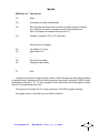
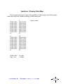
synapse
MIDI controlled matrix patch panel
user
user manual
manual
PHOBOS
Synapse e&oe (c) 1-1-2003
1
Contents
Specification ................................................................................3
Terms ............................................................................................4
Buttons .........................................................................................4
Modes ...........................................................................................4
To make a patch...........................................................................4
Programs......................................................................................5
Mode 0 - Patch (program) Display .............................................6
Clearing a Program .....................................................................6
Mode 1 - Program Select ............................................................6
Mode 2 - Copy ..............................................................................6
Mode 3 - Merge ............................................................................6
Mode 4 - MIDI Channel Select.....................................................7
Mode 5 - Sysex Dump, single program .....................................7
Mode 6 - Sysex Dump, all programs..........................................7
Mode 7 ..........................................................................................7
Unused .........................................................................................7
POWER and CONNECTION - CAUTION!....................................7
*Buffering .....................................................................................7
Sysex ............................................................................................9
Switcher Data Map ....................................................................10
PHOBOS
Synapse e&oe (c) 1-1-2003
2
Specification
Brief Overview of the digital controlled patch panel:
16 x 16 matrix patch panel. 16 inputs and 16 outputs. Any of the inputs can be patched
to any of the outputs. The signal patch is entirley analogue; no DSP! The patch settings
are digitally controlled and are stored in non-volatile memory.
Patch edit via rotary potentiometers.
128 program memories, can be changed via MIDI progam change
MIDI controller editing of programs
SYSEX program transfer (send and receive)
(hopefully) PC/Mac editer (anyone out their that can help me on this?)
All inputs and outputs are fully buffered*
Will fit in a standard Doepfer style case
White boxes by each socket so socket function can be written in with a suitable pen
(just like a patchbay)
If you apply a sequencial pulse to each of the 16 inputs then you could patch the
outputs for drum sequencing!
LEDs: 256 super-bright red indicators
Jack sockets (3.5mm, mono); 32
MIDI Sockets: In, Out, Thru
Dimensions: 84HP, 3U
Weight: xKg
Power: requires +12V / -12V / +5V, Doepfer style connector (2 PSU slots required)
xAmps
PHOBOS
Synapse e&oe (c) 1-1-2003
3
Terms
lit).
A patch is a single connection made between input and output socket (i.e. a LED is
A program is a collection of patches. There are 256 patch points.
Buttons
There are 5 buttons associated with editing and menu navigation;
Patch
used to toggle on/off patch points, and also to confirm copy/merge/
SYSEX transfer, and to advance program selection by 1 bank when in the appropriate
modes.
Target
turns on/off patch point 'cross hairs'
Mode
selects mode / menu options
Down
program / channel decrement
Up
program / channel increment
Modes
There are 7 modes. When Synapse if switched on it defaults to mode 0
Mode 0
Mode 1
Mode 2
Mode 3
Mode 4
Mode 5
Mode 6
patch status display
program number
copy
merge
MIDI channel
Send current program
Send all programs
shows status of each patch
displays program number
used to copy a program to another
used to merge 2 programs
displays MIDI channel number
to send program data by SYSEX
to send all prodram data by SYSEX
Each time Mode is pressed, the next Mode is selected. After the last Mode is reached,
Synapse will roll over to the first Mode.
To make a patch
ited.
Synapes must be in Mode 0.
First press Target. This will light up the X/Y bars to show which patch is being ed-
The target is moved using the two rotary controls: X and Y. This makes editing quick
and easy.
PHOBOS
Synapse e&oe (c) 1-1-2003
4
Press the Patch button repeatedly to toggle on or off the patch point.
The patch point is edited in real time and stored in the memory.
Pressing Target again will turn off the target bars.
The Patch button will function even when the target is off.
There is no 'recall' feature. Hardly difficult to remember to toggle the patch point to
its previous state!
Editing can also be performed using MIDI controllers;
Controller 1 edits X (input select)
Controller 2 edits Y (output select)
Contoller 3 turns the patch on (value 127) or off (value 0).
To see the patch point selected turn the Target on. Note, patching can be done even
when the target is off.
Edits can be programmed into your MIDI sequencer for automated patching! Note
there is a small minimum amount of time neccessary between sending each toggle message. Time is needed to write the patch to the switcher and RAM IC's.
patch status display
PHOBOS
Synapse e&oe (c) 1-1-2003
5
Programs
There are 128 programs in 8 banks (1-8) of 16 (1-16) programs. The bank number
is displayed on the bottom left 8x8 bloack of LEDs, and the program number is displayed
on the right.
Synapse will respond to MIDI program change information when in Mode 0 only. The
program can be selected using the up/down program change buttons. If in Mode 0, the
program number is briefly displayed when changing program.
Mode 0 - Patch (program) Display
This mode shows the status of each patch. There are 256 patch points. A lit LED
indicates a patch has been made (the switch is on).
Synapse only responds to MIDI whilst in this mode.
Pressing the Program up/down buttons will change and load the next program.
Pressing Target will toggle on/off the 'crosshairs' used to help select the patch point.
Pressing Patch will toggle on/off the patch point selected. This features is active even
when the Target is off.
Synapse will respond to the relevant MIDI controllers for patch editing. It will also
receive program change messages and SYSEX dumps.
Clearing a Program
When in Mode 0, first press and hold the Down button, then whilst still holding Down,
press and hold Up. Continue to hold both down for approx. 3 seconds. When you see the
display clear, you can release the buttons. The cleared progam is stored in memory.
Mode 1 - Program Select
Use this mode to show what program has been selected. In this mode the program
number is displayed permanently until the mode is changed.
Use the up/down buttons to change the program number. Pressing Patch will increment the Bank number by 1.
Mode 2 - Copy
Used to copy the current program data to another location. When in this mode COPY?
will be display plus the current program number. Use the program up/down buttons to
select the destination program number you wish to copy to. Press Patch to do the copy.
The program number will jump to the destination program number. Press Mode at any
point to abort.
Mode 3 - Merge
Used to merge the current program data to another location. When in this mode
MERG? will be display plus the current program number. Use the program up/down buttons
to select the destination program number you wish to merge the data with. This will also
PHOBOS
Synapse e&oe (c) 1-1-2003
6
be the destination where the result is stored. Press Patch to do the merge. The program
number will jump to the destination program number. Press Mode at any point to abort.
Mode 4 - MIDI Channel Select
Select Mode 4 to display the MIDI channel number. Use the up/down buttons to select required MIDI channel. This is a global channel that Synape will send and receive on.
Ensure the correct channel is selected for MIDI operation.
Mode 5 - Sysex Dump, single program
Use this mode to transmit the current program's data out via SYSEX. Press PATCH
to proceed.
Mode 6 - Sysex Dump, all programs
Use this mode to transmit all program data (as 128 single dumps) out via SYSEX.
Press Patch to proceed. Program 0 through to 127 are dumped in order. This may take
some time! Press Mode to abort at any time.
Mode 7
Unused
POWER and CONNECTION - CAUTION!
The switcher IC is expensive. Incorrect installation and use of the patcher can result
in damage to the IC and replacement is expensive and at your cost!
Do not exceed the power supply voltages of +/-12 and 5V.
Do not plug the power cable in incorrectly.
The voltage range of signals that can be patch is +/-12V. Do not exceed.
Doepfers 'mini' 5V power supply probably won't be powerful enought to drive Synapse.
It's small and feeble but Synapse is big and hungry!
It may (or may not) be best to fit Synapse into its own separate case and power supply. It is power hungry and also there is a lot of digital switching going on that may (or
may not!) affect other modules. It maybe a case of try and see. It partly depends on how
sensative and well designed other modules in the case are.
Synapse has only been tested with Analogue Solutions' power supply boards. We
have not tested them with other manufacturers. If you have problems opperating Synapse
from a 3rd party case/power supply it maybe due to power PSU design. Synapse is power
hungry due to buffering 256 LEDs.
*Buffering
Synapse is fully buffered, but there are points to watch.
PHOBOS
Synapse e&oe (c) 1-1-2003
7
An input can be patched to multiple outputs with no cross talk, loss of level or side
efects.
Multiple inputs can be patched to a single output, but the signals are not mixed 'ideally'. The performance is somewhere between an unbuffered matrix panel and an 'ideal'
fully buffered panel. It is possible that the signals may affect each other's levels slightly.
Generally for most patching this will not be a problem, but it may be noticeable for an output
connected to a VCO pitch inputs. But, hey, there are no other digital controlled matrices!
For the egg heads here's a brief decription why;
Each input and output has a standard op-amp buffer. In an ideal world each patch
point connects an in to an out via a reisistance, normally it should be at least 10K ohms.
This would give ideal mixing and no cross talk.
Unfortunately the 16x16 switcher IC used has a patch point resistance of only 200
ohms! There is no way to produce a buffer that will overcome the low patch resistance
which results in crosstalk.
The only alternative is to build a 16x16 digital controlled patch matrix circuit (containing 256 switches!) using discrete compoments - an unrealistic and expensive alternative
I am sure you'll agree!
PHOBOS
Synapse e&oe (c) 1-1-2003
8
Sysex
MIDI Byte (h) Description
F0
Start
7D
manufacturer code (educational)
XX
00= Synapse will store data at current program number location
01= Synapse will store at program location specified below
[Note; Synapse will transmit this byte as 00.]
XX
Program number 0-7Fh (0-127 decimal)
Data follows; (64 bytes) 0X
0X
.
.
.
0X
0X
low nibble of 1st byte
high nibble of 1st.
F7
End
32nd byte low nibble
32nd byte high nibble
Synapse can transmit a single program's data, or all 128 programs' data. When sending
all program data, Synapse will send each program's data as an individual SYSEX dump,
starting and ending F0....F7, i.e. each program is sent individually and the program number
(byte 4) is incremented each time.
See sections on Mode 5 & 6 on how to perform a SYSEX program transmit.
A program can be received any time whilst in Mode 0.
PHOBOS
Synapse e&oe (c) 1-1-2003
9
Switcher / Display Data Map
Each program comprises 32 bytes. Due to MIDI's 7 bit data range, each 8 bit program
data byte is split into 2 nibbles, totalling 64 MIDI data bytes.
1
XXXX XXXX
XXXX XXXX
XXXX XXXX
XXXX XXXX
XXXX XXXX
XXXX XXXX
XXXX XXXX
XXXX XXXX
15
2
XXXX XXXX
XXXX XXXX
XXXX XXXX
XXXX XXXX
XXXX XXXX
XXXX XXXX
XXXX XXXX
XXXX XXXX
16
17
XXXX XXXX
XXXX XXXX
XXXX XXXX
XXXX XXXX
XXXX XXXX
XXXX XXXX
XXXX XXXX
XXXX XXXX
XXXX XXXX
21
18
XXXX XXXX
XXXX XXXX
XXXX XXXX
XXXX XXXX
XXXX XXXX
XXXX XXXX
XXXX XXXX
XXXX XXXX
XXXX XXXX
32
XXXX XXXX
High Low
X = data
= nibbles
PHOBOS
=Byte number
Synapse e&oe (c) 1-1-2003
10