1
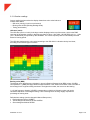
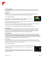
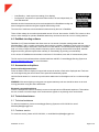
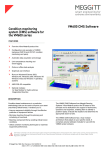
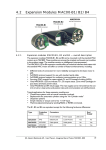
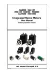
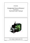
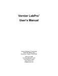
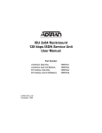
MachineryMate™ 800 operating guide Handheld vibration meter Meggitt Sensing Systems 20511 Seneca Meadows Parkway, Germantown MD 20876, USA Meggitt (Maryland), Inc d/b/a Meggitt Sensing Systems 91938 Rev A Tel: +1 (301) 330-8811 Tel: +1 800 WILCOXON Fax: +1 (301) 330-8873 www.meggittsensingsystems.com www.meggitt.com Contents 1.0 Introduction 2.0 Operation 2.1 Fitting the sensor 2.2 Taking a reading 2.3 Configuration menus 3.0 Asset management 4.0 DataMate trending software 5.0 Accessories and options 6.0 Technical assistance 6.1 Technical assistance 6.2 Customer service 91398 Rev A 11/13 3 3 3 3-6 6-7 7-8 8 8 8 8 8 Page 2 of 8 1.0 Introduction The MachineryMate™ 800 is a simple to use vibration monitoring and analysis tool that allows easy display of vibration signals. The MAC800 automatically performs vibration analysis functions based on machine running speed to help diagnose faults such as unbalance, misalignment and looseness. The system is designed to enable users to take vibration measurements from machinery assets (pumps, motors, fans and bearings). The meter displays vibration frequency plots and allows vibration severity and bearing condition to be monitored. The MAC800 also has an optional strobe attachment for determining machine speed and optional Bluetooth connected headphones for listening to bearing noise. 1.1 Control buttons Turn the meter on by pressing the POWER button. The unit will automatically turn off if not used for 1 minute (can be changed using the Setup Wizard). 1.2 Batteries The MAC800 requires two AA size batteries which can be replaced by removing the battery compartment cover (held in place by six screws). 1.3 Service The MAC800 contains no user serviceable parts. In the unlikely case of malfunction, please return the complete unit to Meggitt Sensing Systems. 2.0 Operation 2.1 Fitting the sensor The MAC800 is supplied with an integral cable connected 780FM-2-J88C sensor that connects to the BNC connector on the meter. The nominal sensitivity of the sensor is 100 mV/g and this is the meter’s default setting for sensor sensitivity. The MAC800 also accepts standard IEPE (constant current) accelerometer and the sensor sensitivity setting can be adjusted to accommodate other sensitivities (default setting: 100 mV/g). 2.2 Taking a reading Taking a reading displays overall vibration numbers for an overall view of the machine’s condition. Press the POWER button to turn the unit on. Place the sensor on a rigid part of the machine as close as possible to the desired measurement point (bearing block) using the magnet mount. Press the POWER button again to take the reading. Note: For best results the sensor should be placed gently onto the measurement point by rolling the magnet onto the machine to avoid any sudden shocks that would be seen as large acceleration peaks by the sensor and could take time to decay. 91398 Rev A 11/13 Page 3 of 8 2.2.1 Vibration readings Once a reading has been taken the display shows three color coded values to indicate alarm status. • ISO value (velocity in inch/s or mm/second) • Bearing noise in BDU (Bearing Damage Units) • Total g (acceleration) ISO value (mm/s) The ISO value (mm/s or inch/s) is the large number displayed at the top of the screen, which is the RMS (average) of the vibration velocity in the frequency band 10 Hz to 1 kHz (600 – 60,000 RPM) or 2 Hz – 1 kHz (120 – 60,000 RPM), as specified by ISO standards. The correct frequency band is automatically selected based on running speed. The ISO value background is color coded according to the ISO 10816-1 vibration velocity level chart, according to the size and type of machine. Bearing noise (BDU) The bearing noise (high frequency vibration) in shown in Bearing Damage Units (BDU), where 100 BDU corresponds to 1 g RMS (average) vibration measured above 1 kHz. BDU is a measure of the wear state of the bearings in the equipment being monitored. The higher the number, the more worn the bearing. 1 g of high frequency vibration (100 BDU) corresponds to a high level of bearing noise and can be considered indicative of a damaged bearing. Think of bearing noise as being roughly equivalent to percentage of bearing wear. Default alarm settings (can be changed in Manual Setup menu) Red background above 100 BDU Yellow background between 50 and 100 BDU Green background below 50 BDU 91398 Rev A 11/13 Page 4 of 8 Total acceleration (g) This is the RMS (average) value of the total vibration acceleration measured by the meter over its entire frequency range (2 Hz to 10 kHz). This reading is shown in units of g (Earth’s gravitational constant, where 2 1 g = 9.81 m/s ). Displacement Pressing the arrow buttons when the reading screen is displayed will display RMS displacement (thou or mm). Press the arrow buttons again to revert to the ISO value display (mm/s or inch/s). 2.2.2 Vibration analysis Press the down arrow to display the readings of vibration velocity (inch/s or mm/s), or displacement (mm or thou), broken down into each of three bands. The display shows the vibration level in frequency ranges based on multiples (1X, 2X and 3X) of the specified machine run speed shown beneath the bars. Note: In order to perform a vibration analysis it is important that the running speed of the machine is entered correctly. This can be done with the Setup Wizard or by using the strobe attachment. The frequency ranges of the VA bands are based on the following multiples of running speed: 1X = Unbalance The level of vibration in the frequency band based on the running speed is usually indicative of how well balanced the machine is. Large vibrations at the running speed indicate that the machine is out of balance. Even a very well balanced machine will typically show some vibration at the running speed but the figure should ideally be quite low (typically less than 2 mm/sec for a medium sized machine). 2X = Misalignment A high level of vibration in the frequency band centered at twice the running speed is a possible indication of misalignment. This is based on the fact that shaft misalignment can result in a double peak in the waveform due to two different centers of gravity (one from each shaft). The accelerometer picks up a peak as each center of gravity passes by, resulting in two positive and two negative peaks each revolution of the shaft. This typically gives rise to a vibration signal at double the running speed of the machine. 3X = Looseness High vibration in the frequency band centered at three times running speed indicates looseness (mounting bolts, weak foundations, etc) as it is not usual to see third order vibration in a machine unless there is structural looseness that is being excited by the vibration of the machine. 2.2.3 Frequency spectrum Press the down arrow button to display vibration levels as a frequency spectrum from 0 to 1 kHz. The heights of the peaks indicate RMS vibration level (mm/s or inch/s) at each frequency point in the spectrum. The readings to the right of show the frequency (Hz or RPM) and the RMS vibration level (inch/s or mm/s) at the position of the cursor (red dotted line). The cursor can be moved with the arrow buttons. 91398 Rev A 11/13 Page 5 of 8 Press the down arrow to increase the resolution of the frequency axis from 100 (10 Hz or 600 RPM resolution) to 800 lines (1.25 Hz or 75 RPM resolution). Increasing the resolution zooms into the frequency spectrum. Scroll using the arrows to display the full spectrum at the higher resolution. 2.2.4 Live update mode The MAC800 can continuously display readings taken at one second intervals. Select live update from the Configuration menu, by holding down the POWER button for two seconds. It is possible to use live update with the basic readings screen, the VA bands screen or 100 line frequency spectrum. Press the POWER button at any time during live update to capture a full (800 line) resolution reading. 2.3 Configuration menus The Configuration menu can be accessed by pressing and holding down the POWER button for two seconds. Navigate the menu with the left and right buttons. Press the POWER button to select the highlighted menu item. 2.3.1 Setup Wizard Setup Wizard allows the machine running speed to be entered and the ISO alarm levels to be set automatically according to the size and type of machine to be monitored. The first screen shows the currently selected running speed in the pre-selected units (Hz or RPM). Change the running speed with the up and down arrow buttons. Press the POWER button again to select machine type (motor or pump). If motor is selected the size must be selected (under or over 300 kW). If pump is selected, specify whether it has an integrated or external drive unit. Selecting the machine type and size allows the ISO alarm levels to be set accordingly, as does specifying the type of mounting (rigid or flexible). Unless a machine is bolted to a concrete floor, its mounting should be considered flexible. Most motors and pumps are mounted on some kind of frame or structure and should be considered flexibly mounted. 2.3.2 Manual setup BDU alarm settings Sets the alarm levels at which the BDU readings change color to be altered. BDU threshold values Warning - readings are amber, 50 BDU Critical - readings are red, 100 BDU Both threshold values can be set independently using up and down arrows. The levels are typical for medium sized machine bearings operating at run speeds from 1000 to 3000 RPM. Larger bearings or higher run speeds may need increased BDU threshold values to identify worn or bad bearings. 91398 Rev A 11/13 Page 6 of 8 Run speed Can be set manually using the up and down arrows. Sensor mV/g Accelerometer sensitivity (mV/g) can be manually set using the up and down arrows from 1 - 1000 mV/g. This enables the resolution and range of the meter to be set by the user. 2.3.3 Device settings There are two pages of Device settings options. Use the arrow buttons to scroll through the options, and the POWER button to select. Auto Off Time Can be set from 1 minute up to a maximum value of 60 minutes, in increments of 1 minute. Brightness Can be set between 1 (least brightness) up to 10 (full brightness). Language The operating language can be selected depending on model. Graph mode Displays the frequency spectrum as either a line graph or a bar graph. Color scheme The display can be configured as standard (full color) or monochrome for convenient viewing in direct sunlight. Time and Date Time and date can be set using the arrow buttons. Units Sets velocity readings to be displayed in mm/s or inch/s. Run speed units Sets run speed unit to Hertz (Hz), revolutions per minute (RPM) or cycles per minute (CPM). 3.0 Asset management Press the Asset Manager button to access the Machines menu. Machines have user-defined names up to 16 characters long. Scroll through the list with the up and down arrows. Select a machine with the circle button to bring up a list of measurement points for that machine. Measurement points also have user-defined names up to 16 characters long. Scroll through the list of measurement points with the up and down arrows and select with the circle button. Options for each measurement point (MP): • • Take Reading – takes a new reading and saves it to this MP Save Reading – saves the previously taken reading to this MP 91398 Rev A 11/13 Page 7 of 8 • • Load Reading – loads a previous reading (for re-display) Configuration - allows the run speed and alarm levels to be set independently for each individual MP Machines and their measurement points are downloaded from DataMate trending and asset management software using the supplied USB docking cradle. The exact list of machines to be downloaded is determined by the user in DataMate. There will also always be a machine downloaded named ‘off route’ that contains 10 MPs. This is done to allow users to save readings for upload to DataMate where they can then be saved to a new or existing machine. 4.0 DataMate trending software DataMate is a PC based software that allows users to view trends of vibration readings taken with the MachineryMate™ 800, to enable comparisons about machine condition. DataMate is intuitive and very easy to drive. Full functionality is described in more detail in its User Manual. The software allows display of vibration data in a variety of ways including vibration frequency spectra, bearing noise and ISO trend plots, waterfall diagrams and can generate reports either manually or automatically (by sending out email alerts). A free version of DataMate accommodates a maximum of 10 machines, each with 10 measurement points. The full version for the software allows unlimited machines and MPs. Contact Meggitt Sensing Systems at [email protected] for more information. 5.0 Accessories and options Strobe and flashlight attachment Press the Strobe button to display run speed and causes the strobe to flash at the displayed rate. Flash rate can be changed using the arrow buttons. Run speed will automatically update. Hold the Strobe button for 2 seconds to put the strobe attachment into flashlight mode for a continuous bright light. WARNING: With strobe lighting moving parts can appear stationary and care should be taken not to touch moving parts when using the strobe attachment. Bluetooth connected headphone Press the Headphones button to wirelessly connect to the optional set of Bluetooth earphones. This enables the user to listen to an audio output of the accelerometer signals so any bearing noise can be heard. 6.0 Technical assistance 6.1 Technical assistance For technical assistance, please contact Meggitt Sensing Systesms at 301-330-8811or email [email protected]. 6.2 Customer service For customer service, please call 301-330-8811, or email [email protected]. 91398 Rev A 11/13 Page 8 of 8