1
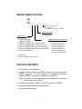
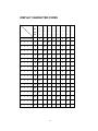
Models: PD3000/PD6000 Series
Customer Displays
2 by 20 character display
USER MANUAL
i
NOTICE
The manufacturer of the POS pole display makes no
representations or warranties, either expressed or implied, by
or with respect to anything in this manual, and shall not be
liable for any implied warranties of fitness for a particular
purpose or for any indirect, special or consequential
damages. Information in this document is subject to change
without notice and does not represent a commitment on the
part of the manufacturer.
FCC NOTICE
This equipment generates, uses, and can radiate radio
frequency energy and if not installed and used in accordance
with this manual, may cause interference to radio
communications. It has been tested and found to comply with
the limits for a Class A digital device pursuant to Subpart J of
Part 15 of FCC Rules, which are designed to provide
reasonable protection against interference when operated in
a commercial environment. Operation of this equipment in a
residential area is likely to cause interference in which case
the user at his own expense will be required to take whatever
measures may be required to correct the interference.
LOGIC CONTROLS, INC.
355 Denton Avenue
New Hyde Park, NY 11040
TEL: (516) 248-0400
FAX: (516) 248-0443
Email: [email protected]
http://www.logiccontrols.com
ii
TABLE OF CONTENTS
FEATURES ............................................................................1
MODEL IDENTIFICATION.....................................................2
CARTON CONTENTS ...........................................................2
INSTALLATION......................................................................3
FUNCTIONAL TEST ..............................................................5
INTERFACE CONNECTION..................................................8
SOFTWARE COMMANDS ..................................................10
HARDWARE CONFIGURATION .........................................11
DISPLAY CHARACTER CODES .........................................12
GENERAL SPECIFICATIONS .............................................13
iii
FEATURES
The PD3000/PD6000 family of pole displays offers a wide range of
high quality features and models to choice from. Listed below are the
features incorporated into each pole display. Not all features are
available in all models. The model identification chart will assist you in
selecting the model best suited to your needs.
The PD3000 family has the industry standard 5mm high vacuum
fluorescent 5x7 pixel display. The PD6000 family has a pixel height of
11.25mm, one of the largest vacuum fluorescent displays on the
market today.
Features - All Models
•
•
•
•
•
•
•
•
•
•
•
Bright green fluorescent display
Supports high speed serial protocol: up to 19,200 baud rate, 1 stop
bit
Automatic message scrolling
Two line display with 20 characters per line
Matched optical lens for better viewing contrast
Ergonomic design
Direct RS232C or parallel interface
Long life and trouble free operation
Five adjustable viewing angles
Simple installation
Available with 120V or 220V Power Adapters
Features - Model dependent
•
•
•
•
•
•
•
•
Emulation of other popular command sets
User definable character
Parallel pass-thru
True RS232C pass-thru
Real time clock
One time message scrolling
Ability to disable attention code
Ability to change attention code
1
MODEL IDENTIFICATION
PD3
or
PD6 __ __ __ - __ __
Blank = No Pass Thru
PT = Pass Thru
25 = DB25F connector to computer
POWER ADAPTER
0 = 120VAC*
1 = 220VAC
COMMAND SET
0 = LOGIC CONTROLS*
1 = LOGIC CONTROLS
SERIAL/PARALLEL INTERFACE
WITH PASS-THRU
0 = SERIAL 9600 BAUD*
2 = SPECIAL COMMAND SET 1 (Aedex emulation)
1 = SERIAL 600 BAUD
3 = SEPCIAL COMMAND SET 2 (Noritaki emulation)
2 = SERIAL 1200 BAUD
4 = SPECIAL COMMAND SET 3 (Epson D202 emulation)
3 = SERIAL 2400 BAUD
5 = SPECIAL COMMAND SET 4 (Ultimate PD1100XL/XLT)
4 = SERIAL 4800 BAUD
9 = OPOS COMMAND SET
5 = SERIAL 19200 BAUD
9 = PARALLEL INTERFACE
* Default Values
** Call for description of Command Sets
CARTON CONTENTS
1. Pole display, pre-assembled.
2. Interface cable, comes with a DB9F connector (to computer) and a
DIN6F connector (to pole display) as standard equipment.
Optional DB25F connector (to computer) is available.
Note: This cable is only supplied with standard serial pole displays
with no pass-thru function.
3. Transformer adapter 120VAC to 6.0VAC (optional 220VAC).
4. Metal base plate with mounting hardware.
5. Quick Installation Guide.
2
INSTALLATION
Your PD3000/PD6000 family of pole displays has been preassembled to make the installation as simple as possible.
Serial Interface Non-pass-thru Models Installation
1. Mount the pole display to the metal base plate using the
mounting hardware provided.
2. The pole display can be used in a freestanding mode or
attached to the counter using the remaining mounting
hardware.
3. Connect the round DIN6M connector from the pole display to
the round DIN6F connector of the interface cable.
4. Connect the DB9F connector to the computer’s serial COM1 or
COM2 port.
5. Connect the female phone jack of the power adapter to the
male phone jack of the interface cable.
6. Plug the power adapter into a 120VAC outlet.
7. A start up text message (LOGIC CONTROLS POS
COMPONENTS) will be present for a short time. When this
message disappears the cursor will be displayed at the leftmost digit of the top row.
Parallel Interface Non-pass-thru Models Installation
1. Mount the pole display to the metal base plate using the
mounting hardware provided.
2. The pole display can be used in a freestanding mode or
attached to the counter using the remaining mounting
hardware.
3. Connect the DB25M connector to the computer’s parallel
printer port (LPT1).
4. Connect the female phone jack of the power adapter to the
male phone jack of the pole display cable.
5. Plug the power adapter into a 120VAC outlet.
6. A start up text message (LOGIC CONTROLS POS
COMPONENTS) will be present for a short time. When this
message disappears the cursor will be displayed at the leftmost digit of the top row.
3
Serial Interface Pass-thru Models Installation
1 Mount the pole display to the metal base plate using the
mounting hardware provided.
2 The pole display can be used in a freestanding mode or
attached to the counter using the remaining mounting
hardware.
3 Connect the DB25M connector to the peripheral device or a
serial pass-thru terminator (optional accessory). Turn on power
of the peripheral device.
4 Connect the DB9F connector to the computer’s serial COM1 or
COM2 port.
5 Connect the female phone jack of the power adapter to the
male phone jack of the pole display cable.
6 Plug the power adapter into a 120VAC outlet.
7 A start up text message (LOGIC CONTROLS POS
COMPONENTS) will be present for a short time. When this
message disappears the cursor will be displayed at the leftmost digit of the top row.
Parallel Interface Pass-thru Models Installation
1 Mount the pole display to the metal base plate using the
mounting hardware provided.
2 The pole display can be used in a freestanding mode or
attached to the counter using the remaining mounting
hardware.
3 Connect the DB25F connector to the peripheral device or
parallel pass-thru terminator (optional accessory). Turn on
power of the peripheral device.
4 Connect the DB25M connector to the computer’s parallel
printer port (LPT1).
5 Connect the female phone jack of the power adapter to the
male phone jack at the DB25M/DB25F connector.
6 Plug the power adapter into a 120VAC outlet.
7 A start up text message (LOGIC CONTROLS POS
COMPONENTS) will be present for a short time. When this
message disappears the cursor will be displayed at the leftmost digit of the top row.
4
FUNCTIONAL TEST
The following test sequence will verify that your pole display is
working properly. Before you start this procedure, you must install the
pole display correctly as outlined under the INSTALLATION section.
The functional test should be done under MSDOS command prompt
by booting up the computer in DOS mode, or shell out to DOS prompt
(in window95/98/ME) or COMMAND prompt (in windows NT/2000).
NOTE: The actual key entries in the text below are enclosed within quotation
marks ( “ ” ). Do not type the quotation marks as part of your entries.
Serial Interface Pole Displays Functional Test
This test procedure assumes the pole display is connected to COM1
of the computer. If COM2 is being used, type COM2 where COM1 is
called out.
Close all opened application programs that use the same COM port
before going into DOS command prompt. Enter the following
command lines to open the COM port for communication with the pole
display:
Type “MODE COM1 96,N,8,1” and press the ENTER key.
Type “TYPE CON>COM1” and press the ENTER key.
PD3000, PD3300, PD3400, PD3500, PD3900, PD6000, PD6300,
PD6400, PD6500 and PD6900
1. Type “ABCDEFGH” and press ENTER key. The display will show
“ABCDEFGH” on the first line.
2. To end the test press Ctrl-C (hold down Ctrl and press C).
PD3200 and PD6200
1. Type “!#1ABCDEFGH” and press ENTER key. The display will
show “ABCDEFGH” on the first line.
2. To end the test press Ctrl-C (hold down Ctrl and press C).
5
PD3100-PT, PD3300-PT, PD3400-PT, PD3500-PT, PD6100-PT,
PD6300-PT, PD6400-PT and PD6500-PT
1. Type “ABCDEFGH” and press ENTER key. The display will show
“ABCDEFGH” on the first line.
2. Type “^APASSTHRU” ( ^A represents Ctrl-A ) and press ENTER
key. The data will be passed through to the peripheral (e.g. a
printer). These characters are not shown on the display.
3. Type “!#^BNUMBER12345”, then press ENTER key. The display
will show “NUMBER12345” on the first line.
4. To end the test press Ctrl-C (hold down Ctrl and press C).
PD3200-PT and PD6200-PT
1. Type “!#1ABCEDFGH” and press ENTER key. The display will
show “ABCDEFGH” on the first line.
2. Type “PASSTHRU” and press ENTER key. The data will be
passed through to the peripheral (e.g. a printer). These
characters are not shown on the display.
3. Type “!#1NUMBER12345”, then press ENTER key. The display
will show “NUMBER12345” on the first line.
4. To end the test press Ctrl-C (hold down Ctrl and press C).
Parallel Interface Pole Displays Functional Test
This procedure assumes the pole display is connected to the LPT1
port of the computer. If parallel port LPT2 is being used, type LPT2
where LPT1 is called out.
PD3090, PD3390, PD3490, PD3590, PD3990, PD6090, PD6390,
PD6490, PD6590 and PD6990
1. Type “ECHO ABCDEFGH>LPT1” and press ENTER key. The
display will show “ABCDEFGH” on the first line.
PD3290 and PD6290
1. Type “ECHO !#1ABCEDFGH>LPT1” and press ENTER key. The
display will show “ABCDEFGH” on the first line.
6
PD3190-PT, PD3390-PT, PD3490-PT, PD3590-PT, PD6190-PT,
PD6390-PT, PD6490-PT and PD6590-PT
1. Type “ECHO ABCDEFGH>LPT1” and press ENTER key. The
display will show “ABCDEFGH” on the first line.
2. Type “ECHO ^APASSTHRU>LPT1” (^A represents Ctrl-A) and
press ENTER key. The data will be passed through to the
peripheral (e.g. a printer). These characters are not shown on the
display.
3. Type “ECHO !#^BNUMBER12345>LPT1”, then press ENTER key.
The display will show “NUMBER12345” on the first line.
PD3290-PT and PD6290-PT
1. Type “ECHO !#1ABCDEFGH>LPT1” and press ENTER key. The
display will show “ABCDEFGH” on the first line.
3. Type “ECHO PASSTHRU>LPT1” and press ENTER key. The
data will be passed through to the peripheral (e.g. a printer).
These characters are not shown on the display.
3. Type “ECHO !#1NUMBER12345>LPT1”, then press ENTER key.
The display will show “NUMBER12345” on the first line.
For further testing of OPOS displays (PD3900, PD3990, PD6900 and
PD6990), follow the instructions in the readme.doc file after software
installation.
7
Parallel Interface Connector Configuration
All standard parallel pole displays will have a DB25 male connector. It
is connected to the printer port of the computer.
1.
2.
3.
4.
5.
6.
7.
8.
9.
10.
11.
12-17
18-25
–Strobe
Data 0
Data 1
Data 2
Data 3
Data 4
Data 5
Data 6
Data 7
–Ack
Busy
NC
Ground
DB25M (to computer)
For pass-through models, the display cable comes with a dual
DB25M/F connector. The DB25M is to be connected to the computer
while the DB25F is for connection to the peripheral.
1.
2.
3.
4.
5.
6.
7.
8.
9.
10.
11.
12.
13.
14.
15.
16.
17.
18-25.
–Strobe
Data 0
Data 1
Data 2
Data 3
Data 4
Data 5
Data 6
Data 7
–Ack
Busy
Paper End
Select
-Auto Feed
-Error
-Initialize Printer
-Select In
Ground
DB25M (to computer)
DB25F (to peripheral)
9
SOFTWARE COMMANDS
Logic Controls pole displays are controlled by command codes and
data from the computer. The model of pole display that you have will
determine which command set works with your pole. Refer to the
model identification chart for further information.
For Logic Controls Command Sets, call 516.248.0400 or e-mail:
[email protected]
10
HARDWARE CONFIGURATION
Serial pole displays were factory configured for serial RS232C
interface using the following protocol:
· 9600 Baud Rate
· 8 Data Bits
· 1 Stop Bit
· No Parity
Other optional baud rates are available with factory settings. Refer to
the model identification chart for further information.
11
DISPLAY CHARACTER CODES
D7
0
0
0
0
0
0
0
0
D6
0
0
0
0
1
1
1
1
D5
0
0
1
1
0
0
1
1
D4
0
1
0
1
0
1
0
1
0
1
2
3
4
5
6
7
D3 D2 D1 D0
0
0
0
0
0
DP
SP
0
@
P
‘
p
0
0
0
1
1
DC1
!
1
A
Q
a
q
0
0
1
0
2
DC2
"
2
B
R
b
r
0
0
1
1
3
DC3
#
3
C
S
c
s
0
1
0
0
4
DIM DC4
$
4
D
T
d
t
0
1
0
1
5
MS
%
5
E
U
e
u
0
1
1
0
6
&
6
F
V
f
v
0
1
1
1
7
’
7
G
W
g
w
1
0
0
0
8
BS
(
8
H
X
h
x
1
0
0
1
9
HT
)
9
I
Y
i
y
1
0
1
0
A
LF
*
:
J
Z
j
z
1
0
1
1
B
+
;
K
[
k
{
1
1
0
0
C
,
<
L
\
l
|
1
1
0
1
D
-
=
M
]
m
}
1
1
1
0
E
.
>
N
^
n
~
1
1
1
1
F
/
?
O
_
o
DL
CR
RST
12
GENERAL SPECIFICATIONS
PD3000
PD6000
2
20
5 x 7 plus underline
0.20in. (5.0mm
0.14in. (3.5mm)
ASCII
690 cd/m2
Green-Blue
300,000
2
20
5X7 plus comma
0.44in. (11.25mm)
0.28in. (7.2mm)
ASCII
700 cd/m2
Green-Blue
300,000
2.4 lb.
(w x h x d)
7.9 x 3.4 x 1.75
2.12 x 2.0 x 2.25
4.0 x 0.09 x 8.0
25
2.8 lb.
(w x h x d)
11.0 x 3.25 x 1.75
2.12 x 2.0 x 2.25
4.0 x 0.09 x 8.0
25
OPTICAL:
Number of rows
Number of digits/row
Dot matrix
Digit height)
Digit width
Character format
Brightness (typical)
Display color
MTBF (hours)
MECHANICAL:
Weight
Dimensions (in inches)
Display head
Rectangular base
Base plate
Overall height (typical)
ELECTRICAL:
Adapter input power
Adapter output power
120VAC, 60Hz; optional 220VAC, 50Hz
6VAC, 1000mA
ENVIRONMENTAL:
Operating temperature
Storage temperature
Relative Humidity
Vibration (10 to 55 Hz.)
Shock
0 to +50 o C
-20 to +70 o C
80%, non-condensing
4G’s
40G’s
CABLES & CONNECTORS:
Serial
Display cable
Interface cable
Power adapter
Parallel
Display cable
6-pin DIN (male)
6-pin DIN (female)
DB9 (female); optional DB25 (female)
Phone jack (male)
Phone jack (female)
DB25 (female)
13