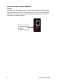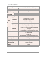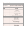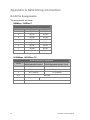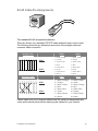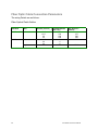
1
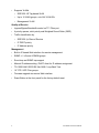
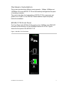
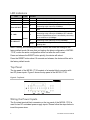
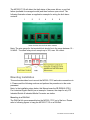
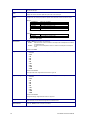
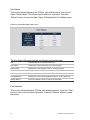
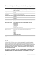
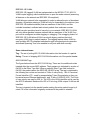
IFS MC355-1T/1S
User Manual
P/N 1076515 • REV A • ISS 14FEB12
Copyright
Trademarks and
patents
© 2012 UTC Fire & Security. All rights reserved.
Interlogix, the IFS MC355-1T/1S and the IFS Brand and logo are trademarks of
UTC Fire & Security.
Other trade names used in this document may be trademarks or registered
trademarks of the manufacturers or vendors of the respective products.
Manufacturer
UTC Fire & Security Americas Corporation, Inc.
2955 Red Hill Avenue, Costa Mesa, CA 92626-5923, USA
Authorized EU manufacturing representative:
UTC Fire & Security B.V.
Kelvinstraat 7, 6003 DH Weert, Netherlands
Version
This document applies to IFS MC355-1T/1S version 00.20.
Certification
FCC compliance
Canada
N4131
Class A: This equipment has been tested and found to comply with the limits
for a Class A digital device, pursuant to part 15 of the FCC Rules. These
limits are designed to provide reasonable protection against harmful
interference when the equipment is operated in a commercial environment.
This equipment generates, uses, and can radiate radio frequency energy
and, if not installed and used in accordance with the instruction manual,
may cause harmful interference to radio communications. Operation of this
equipment in a residential area is likely to cause harmful interference in
which case the user will be required to correct the interference at his own
expense.
This Class A digital apparatus complies with Canadian ICES-003.
Cet appareil numérique de la classe A est conforme à la norme NMB-003 du
Canada.
ACMA compliance
Notice! This is a Class A product. In a domestic environment this product may
cause radio interference in which case the user may be required to take
adequate measures.
European Union
directives
2004/108/EC (EMC directive): Hereby, UTC Fire & Security declares that this
device is in compliance with the essential requirements and other relevant
provisions of Directive 2004/108/EC
2002/96/EC (WEEE directive): Products marked with this symbol cannot be
disposed of as unsorted municipal waste in the European Union. For proper
recycling, return this product to your local supplier upon the purchase of
equivalent new equipment, or dispose of it at designated collection points. For
more information see: www.recyclethis.info.
Contact information
Customer support
www.utcfireandsecurity.com or www.interlogix.com
www.interlogix.com/customer-support
Content
Overview 1
Package Contents 1
Product Description 1
Applications 2
Product Features 3
Hardware Installation 5
MC355-1T/1S Front Panel 5
LED Indicators 6
Top Panel 6
Wiring the Power Inputs 6
Wiring the Fault Alarm Contact 7
Mounting Installation 8
Stand-alone Installation 11
Converter Management 12
Overview 12
Requirements 13
Management Methods 13
Web Management 16
Main Menu 16
System 17
Port Management 29
Converter Configuration 33
VLAN 34
OAM Setup 44
Security 51
Logout 52
Troubleshooting 53
Specifications 55
Contacting Technical Support 57
Appendix A Networking Connection 58
Rj-45 Pin Assignments 58
Fiber Optic Cable Connection Parameters 60
IFS MC355-1T/1S User Manual
i
ii
IFS MC355-1T/1S User Manual
Overview
Package Contents
Thank you for purchasing the IFS 10/100/1000-T to mini-GBIC Industrial
Managed Media Converter, model MC355-1T/1S.
Open the package containing the MC355-1T/1S and carefully unpack it. The box
should contain the following items:
•
The MC355-1T/1S x1
•
User Manual CD x1
•
Quick Installation Guide x1
•
Wall Mount Kit x 4
•
DIN Rail Kit x 1
If any of the items in the package are damaged or missing, please contact your
distributor or IFS sales rep. If possible, retain the original carton and packaging
material in case of need to return the product for repair/replacement.
Product Description
The MC355-1T/1S provides conversion between 10/100/1000Base-T and
1000Base-SX /LX networks. Ethernet signal that allows two type segments
connect easily, efficiently and inexpensively. The mini-GBIC slot accepts Gigabit
mini-GBIC module with LC connectors and single-mode / multi-mode media for
your needs, based on the Gigabit mini-GBIC modules selection, the MC3551T/1S is capable of handling the data from 220m to 70km with high reliability
and flexibility.
The MC355-1T/1S is equipped with remote Web / SNMP interface. With its builtin Web-based management, the MC355-1T/1S offers an easy-to-use, platformindependent management and configuration facility and can be programmed for
advanced management functions - such as IP address Configuration / DHCP
Client function, password setting / firmware upgrade, system reboot / factory
default, port configuration that include TP / Fiber port speed duplex mode setting,
flow control setting and Ingress/Egress bandwidth control setting, converter
configuration that include maximum packet length setting, Broadcast / Multicast /
Unicast storm control setting, 16 IEEE 802.1Q VLAN groups support and
powerful Q-in-Q VLAN function, Quality of Service (QoS), TS-1000 / IEEE
802.3ah OAM function and TCP & UDP filter function. It supports standard
Simple Network Management Protocol (SNMP) and can be managed via any
standard-based management software as well.
IFS MC355-1T/1S User Manual
1
Applications
Access Control System – Traditional Installation
Industrial area Media Converter for data receiving and forwarding
Most of the enterprises perform centralized management to remotely access
machine or other network equipment via Internet network or Fiber optical
network. The MC355-1T/1S media converter can extend the distance of the high
speed data transmission up to 70km and can be managed via the Web interface.
The Gigabit port supporting 9K jumbo packet can handle large amounts of data
transmission in a secure topology linking to a backbone Switch or high-power
servers. The MC355-1T/1S with the slim type IP 30 metal enclosure is ideal for
most Heavy Industrial demanding environments.
2
IFS MC355-1T/1S User Manual
Product Features
Interface
•
1 Mini-GBIC port utilizes the flexibility of the SFP modules
Industrial Conformance
•
12 to 48V DC, redundant power with polarity reverse protect function
•
-30 to 75 Degree C operation temperature support
•
IP-30 metal enclosure
•
Relay alarm for port breakdown
•
Supports 6KVDC Ethernet ESD protection
•
Free fall, Shock and Vibration Stability
•
DIN-Rail and Wall-mountable hardware design
Layer 2 Features
•
Store-and-Forward mechanism
•
Prevents packet loss with back pressure (Half-Duplex) and IEEE 802.3x
PAUSE frame flow control (Full-Duplex)
•
Maximum frame size to 9216 Bytes
•
Loop detection / Broadcast / Multicast / Unicast storm control
IFS MC355-1T/1S User Manual
3
•
Supports VLANs
•
IEEE 802.1Q Tag based VLAN
•
Up to 16 VLAN groups, out of 4K VLAN IDs
•
Management VLAN
Quality of Service
•
Ingress/Egress Bandwidth control on TP / Fiber port
•
4 priority queues, strict priority and Weighted Round Robin (WRR)
•
Traffic classification by:
•
IEEE 802.1p Class of Service
•
IP DSCP priority
•
IP Address priority
Management
•
Built-in IP-based Web interface for remote management
•
SNMP v1 / v2c and 4 RMON groups
•
Event trap and SNMP trap support
•
Manual IP address setting / DHCP client for IP address assignment
•
TS-1000 OAM / IEEE 802.3ah OAM / Loop Back Test
•
16 TCP / UDP Filter groups
•
Firmware upgrade via remote Web interface
•
Reset Button at the front panel for the factory default reset
4
IFS MC355-1T/1S User Manual
Hardware Installation
This product provides three different running speeds – 10Mbps, 100Mbps and
1000Mbps in the same MC355-1T/1S and automatically distinguishes the speed
of incoming connection.
This section describes the functionalities of MC355-1T/1S’s components and
guides how to install it on the DIN Rail. Please read this chapter completely
before the installation.
MC355-1T/1S Front Panel
The Front Panel of the MC355-1T/1S consists of one 1000Base mini-GBIC SFP
slot and one Auto-Sensing 10/100/1000Mbps Ethernet RJ-45 Port. Figure1
shows the front panel of the MC355-1T/1S.
Figure 1: MC355-1T/1S Front Panel
IFS MC355-1T/1S User Manual
5
LED Indicators
LED
P1
P2
FAULT
Color
Green
Green
Green
Fiber LNK /ACT
Green
TP 1000
Green
TP LNK /ACT
Function
Lit
Indicates that power 1 has power.
Lit
Indicates that power 2 has power.
Lit
Indicates that either power 1 or power 2 has no power.
Indicates that the Fiber Optical Port is successfully
Lit
connecting to the network at 1000Mbps.
Indicates the Fiber Optical Port is receiving or sending
Blinks
data.
Indicates that the Gigabit Ethernet Port is successfully
connecting to the network at 1000Mbps. OFF indicates
Lit
that the Gigabit Ethernet Port is successfully connecting
to the network at 10/100Mbps.
Indicates that the Gigabit Ethernet Port is successfully
Lit
connecting to the network at 10/100/1000Mbps.
Indicates that the Gigabit Ethernet Port is receiving or
Blinks
sending data.
Note: Pressing and releasing the RESET button will revert the settings to the
factory default mode. Be sure that you backup the latest configuration of MC3551T/1S; or else the entire configuration will be lost after the unit is reset.
Press and release the RESET button quickly, the device will reboot.
Press the RESET button about 10 seconds and release, the device will be set to
the factory default mode.
Top Panel
The top panel of the MC355-1T/1S consists of a terminal block connector with
two DC power inputs. Figure 2 shows the top panel of the MC355-1T/1S.
Figure 2: Top Panel
Wiring the Power Inputs
The 6-contact terminal block connector on the top panel of the MC355-1T/1S is
used for two DC redundant power supply inputs. Please follow the steps below to
insert the power wires.
6
IFS MC355-1T/1S User Manual
1. Insert the positive / negative DC power wires into the contacts 1 and 2 for
POWER 1 or 5 and 6 for POWER 2. Figure 1 shows PWR1 and PWR2 of the
MC355-1T/1S.
Figure 3: PWR1 & PWR2 of the MC355-1T/1S
V1- V1+
V2- V2+
2. Tighten the wire-clamp screws to prevent the wires from disconnecting.
Figure 4 shows PWR1 and PWR2 pin of the terminal block.
Figure 4: PWR1 & PWR2 of the MC355-1T/1S
1
2
Power 1
-
+
3
4
Fault
5
6
Power 2
-
+
Note: The wire gauge for the terminal block should be in the range between 12 ~
24 AWG.
Wiring the Fault Alarm Contact
The fault alarm contacts are in the middle of the terminal block connector as the
picture shows below. Inserting the wires, the Industrial
IFS MC355-1T/1S User Manual
7
The MC355-1T/1S will detect the fault status of the power failure, or port link
failure (available for managed model) and then forms an open circuit. The
following illustration shows an application example for wiring the fault alarm
contacts.
1
2
3
4
5
6
Insert the wires into the fault alarm contacts
Note: The wire gauge for the terminal block should be in the range between 12 ~
24 AWG. The alarm relay circuit accepts up to 30V, max. 3A current.
Mounting Installation
This section describes how to mount the MC355-1T/1S and make connections to
it. Please read the following sections and perform the procedures in the order
presented.
Note: In the installation steps below, this Manual uses the GE-DSGH-8 (IFS 8
Port Industrial Gigabit Switch) as an example. However, the steps for any IFS
Industrial Switch & Industrial Media Converter are similar.
Mounting to a DIN-Rail
The DIN-Rail kit comes assembled on the MC355-1T/1S out of the box. Please
refer to following figures to hang the MC355-1T/1S on a DIN-Rail.
8
IFS MC355-1T/1S User Manual
1. Lightly press the bottom of the DIN-Rail connector mount into the track.
2. Check that the DIN-Rail connector mount is tightly mounted on the track.
3. Please refer to following procedures to remove the MC355-1T/1S from the
track.
IFS MC355-1T/1S User Manual
9
4. Lightly press the bottom of DIN-Rail connector mount to remove it from the
track.
Mounting to a Wall
To install the MC355-1T/1S on the wall, please follows the instructions described
below.
1. Loosen the screws to remove the DIN Rail from the Media Converter.
2. Place the wall mount plate on the rear panel of the MC355-1T/1S.
10
IFS MC355-1T/1S User Manual
3. Assemble the wall mount plate on the MC355-1T/1S.
4. Use the hook holes at the corners of the wall mount plate to hang the MC3551T/1S on the wall.
Stand-alone Installation
MC355-1T/1S Installation:
To install the MC355-1T/1S with 1000Base-SX / LX SFP, simply complete the
following steps:
1. Connect the DC power to the MC355-1T/1S and verify that the Power LED
illuminates.
2. Turn on the power of the device/station; the PWR LED (Green) should
illuminate when all cables are attached.
3. Make sure that both ends of the fiber cable is connected to the same type of
SFP transceiver, i.e. the 1000Base-SX / 220m & 550m to 1000Base-SX /
220m & 550m, 1000Base-LX / 10km to 1000Base-LX / 10km
4. Connect the fiber cable. Attach the duplex LC connector on the network cable
into the SFP transceiver.
IFS MC355-1T/1S User Manual
11
Figure 5: Stand alone Installation
We recommend using the IFS SFP modules to prevent potential compatibility
issues.
Converter Management
This chapter describes how to manage the MC355-1T/1S. Topics include:
•
Overview
•
Management methods
•
Assigning an IP address to the MC355-1T/1S
•
Logging on to the MC355-1T/1S
Overview
This chapter gives an overview of MC355-1T/1S management. The MC3551T/1S provides a simple WEB browser interface for management purposes.
Using this interface, you can perform various MC355-1T/1S configuration and
management activities, including:
•
•
•
•
•
•
•
•
12
System
Port Management
Converter Configuration
VLAN
Quality of Service
OAM Setup
Security
Logout
IFS MC355-1T/1S User Manual
Requirements
•
Network cables.
For the MC355-1T/1S copper interface, Use standard network (UTP) cables with
RJ-45 connectors.
For the MC355-1T/1S Fiber interface, Use Multi-mode or Single-mode fiber patch
cord with LC connectors.
•
Client PC installed with Ethernet NIC (Network Card)
•
Workstations of clients running Windows 98/ME, NT4.0, 2000/2003/XP, MAC
OS X or later, Linux, UNIX or other platform compatible with TCP/IP
protocols.
•
The client PC installed with a WEB Browser, such as Microsoft Internet
Explorer, Mozilla Firefox, Google Chrome or Apple Safari.
Note: We recommend using Internet Explore 6.0 or above to access the MC3551T/1S.
Management Methods
There are two ways to manage the MC355-1T/1S:
•
Web Management via a network or dial-up connection.
•
Using SNMP Network Management Station.
Web Management
The MC355-1T/1S provides a built-in browser interface. You can manage the
MC355-1T/1S remotely by having a remote host with a Web browser, such as
Microsoft Internet Explorer, Mozilla Firefox, Google Chrome or Apple Safari.
Figure 6: Web Management over Ethernet
IFS MC355-1T/1S User Manual
13
Login to the MC355-1T/1S
The following shows how to startup the Web Management of the MC355-1T/1S.
Please note that the device needs to be configured through an Ethernet
connection and make sure that the administrator PC is set on the same IP subnet
address.
For example, the default IP address of the MC355-1T/1S is 192.168.0.100 (the
factory-default IP address), then the administrator PC should be set at
192.168.0.x (where x is a number between 1 and 254, except 100), and the
default subnet mask should be 255.255.255.0.
Enter the default IP address of http://192.168.0.100 in the address bar of the web
browser.
After entering the username and password (default user name and password is
“admin”) in login screen the Web main screen will appear.
Default IP Address: 192.168.0.100
Default Account: admin
Default Password: admin
Figure 7: Login Web Page screen
Note: For security reasons, please change and keep a record of the new
password after this first setup.
Only lowercase entries are accepted under web interface.
14
IFS MC355-1T/1S User Manual
SNMP Management
You can manage the MC355-1T/1S across a LAN using an SNMP Network
Management Station with a graphical user interface.
This management method lets you monitor statistical counters and set MC3551T/1S parameters from the remote Network
Management Station.
Using this management method:
- The network must run the IP protocol.
- The MC355-1T/1S must have an IP address.
IFS MC355-1T/1S User Manual
15
Web Management
The MC355-1T/1S provides remote Web interface for management function
configuration and make the MC355-1T/1S operate more effectively. A network
administrator can manage and monitor the MC355-1T/1S from the local LAN.
This section indicates how to configure the MC355-1T/1S to enable its
management function.
Main Menu
After a successful login, the main screen appears and displays the MC355-1T/1S
Welcome page.
Figure 8: Web Main screen
As listed at the left of the main screen, the configurable management functions
are shown as below:
•
System – Provides System configuration of the MC355-1T/1S.
•
Port Management – Provides Port Management configuration of MC3551T/1S.
16
IFS MC355-1T/1S User Manual
•
Converter Configuration – Provide Converter configuration of The MC3551T/1S.
•
VLAN – Provides VLAN configuration of The MC355-1T/1S.
•
Quality of Service – Provides Quality of Service (QoS) function of the MC3551T/1S.
•
OAM Setup – Provides OAM Setup function of the MC355-1T/1S.
•
Security – Provides Security function of the MC355-1T/1S.
•
Logout– Provides Logout function of the MC355-1T/1S.
System
System Information
The System Information Web page provides information for the current device.
System Information Web page helps network administrator to identify the
firmware versions, IP Subnet Address and etc. The screen in Figure 9 appears
and the following table describes the System Information menu objects of the
MC355-1T/1S.
Figure 9: System Information Web page screen
IFS MC355-1T/1S User Manual
17
The System Information Web page includes the following fields:
MAC Address
Specifies the MAC address of the MC355-1T/1S.
Software Version
The current software version running on the MC355-1T/1S.
IP Address
The current IP Address of the MC355-1T/1S, the default IP Address is
192.168.0.100.
Subnet Mask
The current Subnet Mask of the MC355-1T/1S, the default Subnet Mask is
255.255.255.0.
Gateway
The current gateway of the MC355-1T/1S, the factory default gateway is
192.168.0.254.
Description
The current description of the MC355-1T/1S, the factory default description
is the MC355-1T/1S.
Temperature
Display current temperature of the MC355-1T/1S in Celsius and Fahrenheit.
Power Status
Display current power supply status of the MC355-1T/1S.
Refresh
Refresh current Web page screen of the MC355-1T/1S.
IP Configuration
The IP Configuration includes the DHCP Client, IP Address, Subnet Mask,
Gateway and Description. Figure 10 illustrates the IP Configuration screen and
the following table describes the IP Configuration object of the MC355-1T/1S.
Figure 10: IP Configuration Web page screen
18
IFS MC355-1T/1S User Manual
The IP Configuration Web page screen includes the following configurable data:
DHCP Client
Disable or enable the DHCP Client function of the MC355-1T/1S, the factory
default mode is Disable.
IP Address
Assigns a new IP address for the MC355-1T/1S, the factory default IP address
is 192.168.0.100.
Subnet Mask
Assigns a new subnet mask for the MC355-1T/1S, the factory default subnet
mask is 255.255.255.0.
Gateway
Assigns a new gateway for the MC355-1T/1S, the factory default gateway is
192.168.0.254.
Description
Input a new description for the MC355-1T/1S, up to a maximum of 32
characters allowed.
Apply Button
Press “Apply” button for save current configuration of the MC355-1T/1S.
Note: If you forget the IP subnet address after changing the default value, press
the "Reset" button located at the front panel of MC355-1T/1S for 10 seconds to
restore the device to the factory settings.
Password Setting
This function helps the administrator to login securely to the Web admin page.
Figures 11 & 12 illustrate the Password Setting screen of the MC355-1T/1S.
Figure 11: Password Setting Web page screen
IFS MC355-1T/1S User Manual
19
Figure 12: Password Setting Successful Web page screen
The Password Setting Web page includes the following configurable data:
Login Name
Displays the user name (admin).
Old Password
The old password needs to be entered before entering the new password.
New Password
Specifies the new password. The password characters are not displayed.
(The maximum length is 16 characters)
Confirm
This confirms the new password. The password entered into this field must be
exactly the same as the password entered in the Password field.
Apply Button
Press the “Apply” button to save the latest configuration of the MC355-1T/1S.
Firmware Upgrade
This function is used for a Firmware Upgrade of the MC355-1T/1S. Figure 13
illustrates the Firmware Upgrade Mode screen.
20
IFS MC355-1T/1S User Manual
Figure 13: Firmware Upgrade Web page screen
Press the “Browse” button to find the firmware location on the administrator PC.
Figure 14: Firmware Upgrade Web page screen
IFS MC355-1T/1S User Manual
21
After selecting the correct firmware file on the administrator PC, press the
“Upgrade” button to start the firmware upgrade process.
Figure 15: Firmware Upgrade Web page screen
WARNING: Do not power off the MC355-1T/1S until the update process is
complete.
WARNING: Do not quit the Firmware Upgrade page without pressing the
“Upgrade” button - after the image is loaded. Or the system won’t apply the new
firmware.
22
IFS MC355-1T/1S User Manual
Figure 16: Firmware Upgrade Web page screen
When the firmware upgrade process is completed a confirmation screen will
appear as illustrated in Figure 17. To re-login to the MC355-1T/1S, click on the
"here" link. Figure 18 illustrates the Login screen.
Figure 17: Firmware Upgrade Web page screen
IFS MC355-1T/1S User Manual
23
Figure 18: Login Web page screen
SNMP Management
This function provides SNMP Management and SNMP Trap Receiver
Configuration functions of the MC355-1T/1S as illustrated in Figures 19 & 20.
Figure 19: SNMP Management Web page screen
24
IFS MC355-1T/1S User Manual
The SNMP Management Web page includes the following configurable data:
SNMP Agent
Disable or enable the SNMP Agent function, the default mode is
“Disable”.
SNMP Read
Community
Input the characters for SNMP Read Community, up to a maximum of
16 characters.
SNMP Write
Community
Input the characters for SNMP Write Community, up to a maximum of
16 characters.
System Name
Input the characters for System Name, up to a maximum of 16
characters.
System Location
Input the characters for System Location, up to a maximum of 16
characters.
Contact
Input the characters for Contact person, up to a maximum of 16
characters.
Apply Button
Press the “Apply” button for save the latest configuration of the MC3551T/1S.
Note: The MC355-1T/1S supports SNMP v1/v2c protocol.
Figure 20: SNMP Trap Receiver Configuration Web page screen
IFS MC355-1T/1S User Manual
25
The SNMP Trap Receiver Configuration Web page includes the following
configurable data:
SNMP Trap
Disable or enable the SNMP Trap function, the default mode is
“Disable”.
SNMP Trap
Destination
Input the IP address of SNMP Trap Destination.
Trap
Event
Cold Start
When the MC355-1T/1S executes Cold Start operation, the
administrator PC (SNMP Trap Destination) will receive a Cold Start
Trap.
Warm
Start
When the MC355-1T/1S executes Warm Start operation, the
administrator PC (SNMP Trap Destination) will receive a Warm
Start Trap.
Login Fail
When a Web login fail situation appears on the MC355-1T/1S, the
administrator PC (SNMP Trap Destination) will receive a Login Fail
Trap.
Link Up
When TP or Fiber port connection is build up, the administrator PC
(SNMP Trap Destination) will receive a Link Up Trap.
Link
Down
When TP or Fiber port connection is Disconnect, the administrator
PC (SNMP Trap Destination) will receive a Link Down Trap.
Apply Button
Press the “Apply” button to save the latest configuration of the
MC355-1T/1S.
Factory Default
This function is used to set the MC355-1T/1S to its factory default settings.
Figure 21: Factory Default Web page screen
26
IFS MC355-1T/1S User Manual
Figure 22: Factory Default Web page screen
Figure 23: Login Web page screen
IFS MC355-1T/1S User Manual
27
System Reboot
This function is used to reboot the MC355-1T/1S media converter.
Figure 24: System Reboot Web page screen
Figure 25: System Reboot Web page screen
28
IFS MC355-1T/1S User Manual
Figure 26: Login Web page screen
Port Management
Port Configuration
This screen displays the TP/Fiber port status. The Link Status on the screen
displays the current connection speed and duplex mode information or, shows a
connection issue with a "Down" status indicator highlighted in red. Press the
“Refresh” button to refresh the data. Figure 27 illustrates the port configuration
screen.
Figure 27: Port Configuration Web Page screen
IFS MC355-1T/1S User Manual
29
Port
Link
Mode
TP port and Fiber port.
Displays the current connection speed and duplex mode of TP or Fiber port.
Configures the TP or Fiber port speed and operation mode. Draw the menu bar to select the mode.
TP Port:
y
y
y
y
y
y
Auto Speed
1000 Full
100 Full
100 Half
10 Full
10 Half
Setup Auto negotiation
Sets 1000Mbps Full-Duplex mode
Sets100Mbps Full-Duplex mode
Sets 100Mbps Half-Duplex mode
Sets 10Mbps Full-Duplex mode
Sets 10Mbps Half-Duplex mode
Default mode: Auto Speed.
Fiber Port:
y Auto Speed
y 1000 Full
Setup Auto negotiation
Sets 1000Mbps Full-Duplex mode
Default mode: Auto Speed.
Flow Control
Disable or Enable Flow Control of TP or Fiber port.
Enable:
IEEE 802.3x Flow Control is enabled on Full-Duplex mode or Backpressure is enabled
on Half-Duplex mode
Disable:
No Flow Control or backpressure function on neither the Full-Duplex nor Half-Duplex
mode
Default mode: Disable
Ingress Rate Limit
The value of inbound traffic limitation in kilobit-per-second (kbps). The available options are :
• No Limit
• 512K
• 1M
• 2M
• 4M
• 8M
• 10M
• 50M
• 100M
• 500M
Default mode: No Limit
The Ingress Rate Limit configuration field as shown in Figure 28.
Egress Shaping
The value of outbound traffic limitation in kilobit-per-second (kbps). The available options are :
• No Limit
• 512K
• 1M
• 2M
• 4M
• 8M
• 10M
• 50M
• 100M
• 500M
Default mode: No Limit
The Egress Shaping configuration field as show in Figure 29.
Apply Button
Refresh Button
30
Press this button for save the latest configuration of the MC355-1T/1S.
Press the “Refresh” button to refresh current status.
IFS MC355-1T/1S User Manual
Figure 28: Port Configuration-Ingress Rate Limit Web Page screen
Figure 29: Port Configuration-Egress Shaping Web Page screen
IFS MC355-1T/1S User Manual
31
Port Status
This function allows displaying the TP/Fiber port detailed status, such as Link
Status, Duplex Mode, Flow control, Speed and Auto negotiation. Press the
“Refresh” button to renew the data. Figure 30 illustrates the Port Status screen.
Figure 30: Port Status Web Page screen
The Port Status Web page includes the following configurable data:
Port
Indicates that the TP port and Fiber port.
Link Status
Displays the current link status of TP and Fiber port.
Duplex Mode
Displays the current duplex mode of TP and Fiber port.
Flow Control
Displays the current Flow Control status of TP and Fiber port.
Speed
Displays the current speed mode of TP and Fiber port.
Auto Negotiation
Displays the current Auto negotiation status of TP and Fiber port.
Refresh Button
Press the “Refresh” button to refresh current status.
Port Statistics
This function allows displaying TP/Fiber port detailed statistics. Press the “Clear”
button to clear current counter information. Press the “Refresh” button to renew
the screen.
32
IFS MC355-1T/1S User Manual
Figure 31: Port Statistics Web Page screen
Converter Configuration
This screen provides several settings for the MC355-1T/1S as Maximum Packet
length, Loop detection, storm control, etc.
Figure 32: Converter Configuration Web Page screen
IFS MC355-1T/1S User Manual
33
The Converter Configuration Web page includes the following configurable data:
Maximum Packet Length
Provides maximum packet lengths setting for the MC355-1T/1S,
available options are 1518 bytes, 2048 bytes and 16K bytes. Default
mode is 16K bytes.
Loop Detection
Disable or enable the Loop detection function. Default mode is
Disable.
Loop Status
Displays the Loop Detection status.
Broadcast Storm Control
Disable or enable the Broadcast Storm Control function. Default mode
is Disable.
Multicast Storm Control
Disable or enable the Multicast Storm Control function. Default mode
is Disable.
Unicast Storm Control
Disable or enable the Unicast Storm Control function. Default mode is
Disable.
Storm Trigger Counter
Storm Trigger Counter setting and the available options are:
64 broadcast
32 broadcast
16 broadcast
8 broadcast
Default mode is 64 broadcast.
Storm Filter Timer
Storm Filter Timer setting and the available options are:
800ms
400ms
200ms
100ms
Default mode is 800ms.
Apply Button
Press this button to save the latest configuration of the MC355-1T/1S.
VLAN
A Virtual LAN (VLAN) is a logical network grouping that limits the broadcast
domain. It allows you to isolate network traffic so only members of the VLAN
receive traffic from the same VLAN members. Basically, creating a VLAN from a
converter is logically equivalent of reconnecting a group of network devices to
another Layer 2 switch. However, all the network devices are still plugged into
the same switch physically.
The MC355-1T/1S supports IEEE 802.1Q (tagged-based) VLAN setting in web
management page. In the default configuration, VLAN support is “No VLAN”.
34
IFS MC355-1T/1S User Manual
IEEE 802.1Q VLANs
IEEE 802.1Q (tagged) VLAN are implemented on the MC355-1T/1S. 802.1Q
VLAN require tagging, which enables them to span the entire network (assuming
all devices on the network are IEEE 802.1Q-compliant).
VLAN allows a network to be segmented in order to reduce the size of broadcast
domains. All packets entering a VLAN will only be forwarded to the stations (over
IEEE 802.1Q enabled switches) that are members of that VLAN, and this
includes broadcast, multicast and unicast packets from unknown sources.
VLAN can also provide a level of security to your network. IEEE 802.1Q VLAN
will only deliver packets between stations that are members of the VLAN. Any
port can be configured as either tagging or untagging. The untagging feature of
IEEE 802.1Q VLAN allows VLAN to work with legacy switches that don't
recognize VLAN tags in packet headers. The tagging feature allows VLAN to
span multiple 802.1Q-compliant switches through a single physical connection
and allows Spanning Tree to be enabled on all ports and work normally.
Some relevant terms:
Tag - The act of putting 802.1Q VLAN information into the header of a packet.
Untag - The act of stripping 802.1Q VLAN information out of the packet header.
802.1Q VLAN Tags
The figure below shows the 802.1Q VLAN tag. There are four additional octets
inserted after the source MAC address. Their presence is indicated by a value of
0x8100 in the Ether Type field. When a packet's Ether Type field is equal to
0x8100, the packet carries the IEEE 802.1Q/802.1p tag. The tag is contained in
the following two octets and consists of 3 bits of user priority, 1 bit of Canonical
Format Identifier (CFI - used for encapsulating Token Ring packets so they can
be carried across Ethernet backbones), and 12 bits of VLAN ID (VID). The 3 bits
of user priority are used by 802.1p. The VID is the VLAN identifier and is used by
the 802.1Q standard. Because the VID is 12 bits long, 4094 unique VLAN can be
identified.
The tag is inserted into the packet header making the entire packet longer by 4
octets. All of the information originally contained in the packet is retained.
IFS MC355-1T/1S User Manual
35
802.1Q Tag
User Priority
3 bits
TPID (Tag Protocol Identifier)
Destination
Address
Source
Address
12 bits
TCI (Tag Control Information)
2 bytes
Ethernet
Type
VLAN TAG
6 bytes 6 bytes
VLAN ID (VID)
1 bits
2 bytes
Preamble
CFI
4 bytes
2 bytes
Data
FCS
46-1500 bytes 4 bytes
The Ether Type and VLAN ID are inserted after the MAC source address, but
before the original Ether Type/Length or Logical Link Control. Because the
packet is now a bit longer than it was originally, the Cyclic Redundancy Check
(CRC) must be recalculated.
Adding an IEEE802.1Q Tag
Original Ethernet
Dest. Addr.
Src. Addr.
Length/E. type
Dest. Addr.
Src. Addr.
E. type
Data
Tag
Old CRC
Length/E. type
Data
New CRC
New Tagged Packet
Priority
CFI
VLAN ID
Port VLAN ID
Packets that are tagged (are carrying the 802.1Q VID information) can be
transmitted from one 802.1Q compliant network device to another with the VLAN
information intact. This allows 802.1Q VLAN to span network devices (and
indeed, the entire network – if all network devices are 802.1Q compliant).
Every physical port on a switch has a PVID. 802.1Q ports are also assigned a
PVID, for use within the switch. If no VLAN are defined on the switch, all ports
are then assigned to a default VLAN with a PVID equal to 1. Untagged packets
are assigned the PVID of the port on which they were received. Forwarding
decisions are based upon this PVID, in so far as VLAN are concerned. Tagged
packets are forwarded according to the VID contained within the tag. Tagged
packets are also assigned a PVID, but the PVID is not used to make packet
forwarding decisions.
Tag-aware switches must keep a table to relate PVID within the switch to VID on
the network. The switch will compare the VID of a packet to be transmitted to the
VID of the port that is to transmit the packet. If the two VID are different the
switch will drop the packet. Because of the existence of the PVID for untagged
36
IFS MC355-1T/1S User Manual
packets and the VID for tagged packets, tag-aware and tag-unaware network
devices can coexist on the same network.
A switch port can have only one PVID, but can have as many VID as the switch
has memory in its VLAN table to store them.
Because some devices on a network may be tag-unaware, a decision must be
made at each port on a tag-aware device before packets are transmitted –
should the packet to be transmitted have a tag or not? If the transmitting port is
connected to a tag-unaware device, the packet should be untagged. If the
transmitting port is connected to a tag-aware device, the packet should be
tagged.
Default VLANs
The MC355-1T/1S initially configures one VLAN, VID = 1, called "default." The
factory default setting assigns all ports on the MC355-1T/1S to the "default". As
new VLAN are configured in Port-based mode, their respective member ports are
removed from the "default."
VLAN Group
This function allows disable or enable the IEEE 802.1Q VLAN operation mode.
Press the “Apply” button to save the latest configuration of the MC355-1T/1S.
Figure 33: VLAN Group Web Page screen
IFS MC355-1T/1S User Manual
37
Figure 34: VLAN Group Web Page screen
The VLAN Group Web page includes the following configurable data:
VLAN Mode
Disable or enable the IEEE 802.1Q VLAN operation mode. Default
mode is Disable.
Management VLAN
Group
Define the Management VLAN group. Default mode is VLAN1.
VLAN Group
Indicates that the VLAN Group from 1 to 16.
VID
Defines the VLAN Group ID and the available options are 1 to 4094.
Member
Apply Button
TP
Assigns the TP port into VLAN Groups.
Fiber
Assigns the Fiber port into VLAN Groups.
Press this button to save the latest configuration of the MC3551T/1S.
Note: When changing the Management VLAN Group settings, please make sure
that the TP or fiber port that connects to the administrator PC is in the same
VLAN Group; otherwise, connection will be lost making the further management
impossible until the unit is reset to factory defaults by pressing the reset button
for 10 seconds.
VLAN Per Port Setting
This function provides IEEE 802.1Q VLAN per port setting for TP and Fiber port
of MC355-1T/1S. Press the “Apply” button to save the current configuration of
MC355-1T/1S. Figure 35 illustrates 802.1Q VLAN per Port Setting screen.
38
IFS MC355-1T/1S User Manual
Figure 35: VLAN Per Port Setting Web Page screen
The VLAN Per Port Setting Web page includes the following configurable data:
Port
TP port and Fiber port.
Egress Link Type
Provides Egress Link Type options for TP port and Fiber port, the
available options are:
• UnTag
• Tag
• ByPass
Default mode is UnTag.
PVID
Allows PVID assignment for the TP port and the Fiber port, the
available options are 1 to 4094. Default mode is 1 to 16.
Accept Frame Type
Define the Accept Frame Type and the available options are
• All
• Tagged Only
Default mode is All.
Ingress Filter
Disable or enable the Ingress Filter function. Default mode is Enable.
Apply Button
Press this button to save the latest configuration of the MC355-1T/1S.
Q-in-Q VLAN Setting
When enabling the Q-in-Q function, MC355-1T/1S can insert or remove 4-bytes
Q-in-Q tag in the received 802.3 frames. The Q-in-Q tag value is a user defined
value. And in default condition, the Q-in-Q tag format is same as VLAN tag. On a
regular application, enable two port’s Q-in-Q function; UTP Port set to insert Q-inQ tag and Fiber port set to remove Q-in-Q Tag. For aggregation layer switch, it
will check Q-in-Q tag only, and ignore the VLAN tag from the corridor layer
IFS MC355-1T/1S User Manual
39
switch. Q-in-Q Tag ether type can be set same as VLAN tag ether type or other
values.
This function provides IEEE 802.1Q Q-in-Q VLAN setting of MC355-1T/1S. Press
the “Apply” button to save the latest configuration.
Figure 36: Q-in-Q VLAN setting Web Page screen
The Q-in-Q VLAN setting Web page includes the following configurable data:
Q-in-Q Enable
Disable or enable the Q-in-Q VLAN function. Default mode is
Disable.
Q-in-Q Direction
Provides two directions for Q-in-Q function, the available options
are:
UTP is customer port, Fiber is main port
Fiber is customer port, UTP is main port
Default mode is UTP is customer port, Fiber is main port.
Out Layer VLAN Tag
EtherType (HEX)
Defines the Out Layer VLAN Tag Ether Type and default mode is
0x8100.
Out Layer VLAN VID
(DEC)
Defines the Out Layer VLAN VID and default mode is 1.
Apply Button
Press this button to save the latest configuration of the MC3551T/1S.
Quality of Service
Quality of Service (QoS) is an advanced traffic prioritization feature that allows
you to establish control over network traffic. QoS enables you to assign various
40
IFS MC355-1T/1S User Manual
grades of network service to different types of traffic, such as multi-media, video,
protocol-specific, time critical, and file-backup traffic.
QoS reduces bandwidth limitations, delay, loss, and jitter. It also provides
increased reliability for delivery of data and allows prioritization of certain
applications across the network. You can define exactly how you want the switch
to treat selected applications and types of traffic.
You can use QoS on your system to:
•
Control a wide variety of network traffic by:
•
Classifying traffic based on packet attributes.
•
Assigning priorities to traffic (for example, to set higher priorities to
time-critical or business-critical applications).
•
Applying security policy through traffic filtering.
•
Provide predictable throughput for multimedia applications such as video
conferencing or voice over IP by minimizing delay and jitter.
•
Improve performance for specific types of traffic and preserve performance as
the amount of traffic grows.
•
Reduce the need to constantly add bandwidth to the network.
•
Manage network congestion.
This function provides Quality of Service setting of MC355-1T/1S. Press the
“Apply” button to save the current configuration.
Figure 37: Quality of Service Web Page screen
IFS MC355-1T/1S User Manual
41
The Quality of Service Web page includes the following configurable data:
QoS Mode
Provides 4 different QoS mode for operation, the available options
are:
Disable
802.1p Tag Priority
The 802.1p Tag Priority field as show in Figure 38.
IP Address Priority
The IP Address Priority field as show in Figure 39.
IP DSCP Priority
The IP DSCP Priority field as show in Figure 40.
Default mode is Disable.
Scheduling
Provides two scheduling methods for Quality of Service, the available
options are:
Strict Priority
Weighted Round Robin (16:8:4:1)
Default mode is Strict Priority.
Apply Button
Press this button to save the latest configuration of the MC3551T/1S.
Figure 38: 802.1p Tag Priority Web Page screen
42
IFS MC355-1T/1S User Manual
Figure 39: IP Address Priority Web Page screen
Figure 40: IP DSCP Priority Web Page screen
Note: DSCP Value has two input settings area. The default DSCP value is 63
and these two fields are both for customized DSCP values.
IFS MC355-1T/1S User Manual
43
OAM Setup
Local TS-1000 OAM Setup
This function provides Local TS-1000 OAM Setup of MC355-1T/1S. Press the
“Apply” button to save the latest configuration of the MC355-1T/1S.
Figure 41: Local TS-1000 OAM Setup Web Page screen
The Local TS-1000 OAM Setup Web page includes the following configurable
data:
TS-1000 OAM State
Disable or enable the TS-1000 OAM operation mode. Default mode is
Disable.
TS-1000 Mode
Provides two TS-1000 modes for operation, the available options are:
Terminal
Center
Default mode is Terminal.
Link Transparent
Disable or enable the Link Transparent function. Default mode is
Disable.
Link Transparent
Result
Displays the link transparent result.
Apply Button
Press this button to save the latest configuration of the MC355-1T/1S.
44
IFS MC355-1T/1S User Manual
Remote TS-1000 OAM Setup
The Remote TS-1000 OAM Setup is an advanced remote device monitor feature
that allows you to remotely monitor and receive an automatic notify status
indication.
Remote monitor
1. The user instructs the Center Media Converter to issue a status notification
request frame defined in TS-1000 to get status of the terminal Media Converter.
2. The Terminal Media Converter receives the status notification request frame
and sends out a status response frame, which carries its current status.
Autonomous notification
1. The Terminal Media Converter notifies the center Media Converter
autonomously with a status notification indication, if any change occurs in the
status monitored internally by the terminal Media Converter.
2. The Center Media Converter if it is supported notifies the terminal Media
Converter autonomously with a status notification indication, if any change
occurs in the status monitored internally by the center Media Converter.
This function provides Remote TS-1000 OAM Setup of the MC355-1T/1S. Press
the “Apply” button to save the latest configuration of the MC355-1T/1S.
Figure 42: MC355-1T/1S Remote TS-1000 OAM Setup Web Page screen
IFS MC355-1T/1S User Manual
45
Note: Please use the MC355-1T/1S as the remote device.
TS-1000 Loop Back Test
The TS-1000 Loop Back Test is a manual running loop back test to check the
interconnection between two MC355-1T/1S devices.
In-band and out-band Loop back
1. Instruct center Media Converter to issue an OAM frame to request a loop
back test. Terminal begins returning OAM frames as a response to the Media
Converter.
2. Terminal Media Converter runs at loop back mode.
3. Central Media Converter send test frame and terminal Media Converter loop
back the frames. Test frames can be generated from central Managed Media
Converter’s UTP port (Out-Band) or from central Managed Media Converter
(In-Band) automatically.
4. Center Managed Media Converter check the loop back test result after
sending all test frames
5. Instruct the central MC355-1T/1S to end the loop back test.
46
IFS MC355-1T/1S User Manual
This function provides TS-1000 Loop Back Test of the MC355-1T/1S. Press the
“Apply” button to run Loop Back Test and see the TS-1000 Loop Back Test
Result of the MC355-1T/1S, also press the “Refresh” button to renew the Web
screen.
Figure 43: Remote TS-1000 Loop Back Test Web Page screen
The TS-1000 Loop Back Test Web page includes the following configurable data:
TS-1000 Loop Back Test
Send Packet Number
Input the number for packet send and the available options is 1 to 255.
The default is16.
Apply Button
Press this button to save the latest configuration of the MC355-1T/1S.
Refresh Button
Press the “Refresh” button to refresh the current status.
TS-1000 Loop Back Test Result
Result
Displays the TS-1000 Loop Back Test Result. Fail or Pass.
Result counter
Displays the value of Counter Result.
Note: Please use the MC355-1T/1S as the remote device.
802.3ah Setup
When enabling 802.3ah OAM function, all 802.3ah OAMPDU packets will trap to
the embedded CPU. The Software will implement an auto discovery procedure.
With hardware support, the software controls the 802.3ah remote loop back
procedure. Hardware can also detect a dying gasp event and interrupt the CPU
IFS MC355-1T/1S User Manual
47
to send a dying gasp event notification OAMPDU. All the other functions defined
by 802.3ah are implemented using the embedded CPU.
When the remote device is in loop back mode, the hardware can support
changing the looped test frame’s DA, SA or both as user defined. Hardware can
also be set to not change looped test frame.
This function provides 802.3ah Setup of the MC355-1T/1S. Press the “Apply”
button to save the latest configuration of the MC355-1T/1S.
Figure 44: 802.3ah Setup Web Page screen
The 802.3ah Setup Web page includes the following configurable data:
802.3ah OAM State
Disable or enable the 802.3ah OAM State function. Default mode is
Enable.
802.3ah OAM Mode
Choose “Active” or “Passive” for 802.3ah OAM Mode. Default mode
is Passive.
Loopback Reply
Disable or enable the Loopback Reply function. Default mode is
Enable.
Remote OAM Configure
Disable or enable the Remote OAM Configure function. Default mode
is Enable.
Remote OAM
Configuration Result
Displays the Remote OAM Configuration Result.
Apply Button
Press this button to save the latest configuration of the MC3551T/1S.
Note: The 802.3ah function requires a managed device that also supports
802.3ah function.
Please use the MC355-1T/1S as the remote device.
48
IFS MC355-1T/1S User Manual
802.3ah Loop Back Test
The 802.3ah Loop Back Test allows to manually run this loop back test to check
the interconnection between two MC355-1T/1S devices, and to assure that the
remote 802.3ah function can work correctly.
This function provides 802.3ah Loop Back Test of the MC355-1T/1S. To run the
802.3ah Loop Back Test, press the “Apply” button and then "Refresh" button to
renew the screen.
IFS MC355-1T/1S User Manual
49
Figure 45: 802.3ah Loop Back Test Web Page screen
The 802.3ah Loop Back Test Web page includes the following configurable data:
802.3ah Loop Back Test
Send Packet Number
Input the number for packet send and the available options is 1 to 255.
Default is 16.
Packet Length
(Not include CRC)
Input the number for Packet Length and the available options is 60 to
1514. Default is 60.
Apply Button
Press this button to save the latest configuration of the MC355-1T/1S.
Refresh Button
Press the “Refresh” button to refresh current status.
802.3ah Loop Back Test Result
Result
Displays the 802.3ah Loop Back Test Result. Fail or Pass.
Note: The 802.3ah function must work with manageable device that supports
802.3ah function.
Please use the MC355-1T/1S as the remote device.
50
IFS MC355-1T/1S User Manual
Security
This function provides TCP / UDP Filter settings of the MC355-1T/1S. Press the
“Apply” button to save the latest configuration of the MC355-1T/1S.
Figure 46: Security setting Web Page screen
The Quality of Service Web page includes the following configurable data:
Group ID
Input the group ID for TCP / UDP Filter and the available range is 1 to
16.
Action
“Deny” or “Permit” options and default mode is Permit.
Egress Port
Choose “TP” or “Fiber” as Egress Port. Default mode is TP.
Packet Type
Provides IPv4 and Non-IPv4 protocol for further setting.
L4 Protocol
Provides IPv4 and Non-IPv4 protocol for further setting.
IPv4: TCP Any / FTP (21) / HTTP (80), UDP Any / TFTP (69)
Non-IPv4: Any / ARP (0x0806) / IPX (0X8137)
Current List
Display the current TCP / UDP Filter Groups.
Add Button
Press this button to add new TCP / UDP Filter groups into the current
list.
Del Button
Press this button to delete existing TCP / UDP Filter groups from the
current list.
IFS MC355-1T/1S User Manual
51
Logout
This function allows to logout the MC355-1T/1S Media Converter web admin
menu. To logout, press the "OK" button on the popup confirmation window as it
is illustrated in Figure 47 & 48.
Figure 47: Logout Web Page screen
Figure 48: Login Web Page screen
52
IFS MC355-1T/1S User Manual
Troubleshooting
This chapter has supporting information for installers and end-users to solve
potential issues being faced with the IFS MC355-1T/1S media converter. If the
Media Converter is not functioning properly, make sure the Media Converter was
set up according to the instructions in this manual.
The Link LED is not lit
Solution:
1. Check the cable connection and disable duplex mode of the MC355-1T/1S.
2. Check the port configuration of the link partner; and make sure both devices
on each end are set with the same configurations.
Performance seems poor
Solution:
Check the full duplex status of the devices. If one of the devices are set to full
duplex, and the other to half duplex, transmission performance will be affected
negatively.
10/100/1000Base-T port link LED is lit, but the traffic is irregular
Solution:
Check that the attached device is not set to full duplex mode. Some devices use a
physical switch to set the duplex mode, while some use software based settings.
A physically set full duplex setting may prevent the Auto negotiation feature from
recognizing it.
Why the device doesn’t connect to the network
Solution:
Please follow these steps: Check the LNK/ACT LED on the MC355-1T/1S. Try
another port on the connected device. Make sure the cable is installed properly.
Make sure one of the supported types of cables was used. Turn off the power.
After waiting briefly, turn the power on again.
IFS MC355-1T/1S User Manual
53
How can I deal with a forgotten password?
Solution:
The MC355-1T/1S is equipped with a “Reset” button located on the front panel.
Press and hold the button for 10 seconds to reset the device to factory settings.
After the device reboots, login to the Web Management page with the default
user name and password (admin).
54
IFS MC355-1T/1S User Manual
Specifications
Hardware Specifications
Copper Interface
1 x 10/100/1000Base-T RJ-45 Auto-MDI/MDI-X ports
Optic Interface
SFP
Optical Mode
Varies by module
Optic Wavelength
-
Launch
MAX.
-
Power(dBM)
Min.
-
Receive Sensitivity
-
Maximum Input power
10/20Mbps for Half / Full-Duplex
Speed
Twisted-pair
100/200Mbps for Half / Full-Duplex
2000Mbps for Full-Duplex
Fiber-optic
2000Mbps for Full-Duplex
10Base-T: 2-pair UTP Cat. 3,4,5, up to 100 m
Twisted-pair
100Base-TX: 2-pair UTP Cat. 5, up to 100 m
1000Base-T: 4-pair STP Cat 5,6 up to 100m
Cable
y 50/125μm or 62.5/125μm multi-mode fiber cable, up to
Fiber-optic
Cable
LED indicator
Power Input
Power Consumption
Operating Temperature
Operating Humidity
Storage Temperature
Storage Humidity
Dimension (W x D x H)
Weight
Installation
IFS MC355-1T/1S User Manual
220/550m.
y 9/125μm single-mode cable, provides long distance for
10/30/70km (based on fiber transceiver or SFP module)
Power: P1, P2, Fault
TP: LNK/ACT, 1000
Fiber: LNK/ACT
12 to 48V DC
Redundant power with polarity reverse protection function
7.7 Watts/ 26 BTU (maximum)
-30~75 Degree C
5~90% non-condensing
-40~85 Degree C
5~90% non-condensing
5.31” x 3.34” x 1.25” / 135 x 85 x 32 mm
0.932 lbs
DIN rail kit and wall mount ear
55
Management and Layer 2 Features
Management Interface
WEB / SNMP v1, v2c
Port disable/enable
Port Configuration
Auto-negotiation 10/100/1000Mbps Full and Half duplex mode
selection.
Flow Control disable / enable. Bandwidth control on each port.
IEEE 802.1q Tagged Based VLAN , 4K VLAN ID, up to 16
VLAN
VLAN groups
Q-in-Q VLAN
Traffic classification based on :
QoS
• 802.1p priority
• IP DSCP field in IP Packet
• IP Address
Ingress / Egress bandwidth control
Bandwidth Control
• Rate range: 512kbps to 500Mbps
Storm control
• Broadcast / Multicast / Unknown Unicast packet
Standard Conformance
Emissions
FCC Class A, CE Class A
IEEE 802.3 10BASE-T
IEEE 802.3u 100BASE-TX
IEEE 802.3z Gigabit SX/LX
Standard
IEEE 802.3ab Gigabit 1000T
IEEE 802.3x Flow Control and Back pressure
IEEE 802.1p Class of service
IEEE 802.1Q VLAN Tagging
IEEE 802.3ah OAM
IEC60068-2-32 (Free fall)
Stability
IEC60068-2-27 (Shock)
IEC60068-2-6 (Vibration)
56
IFS MC355-1T/1S User Manual
Contacting Technical Support
Contact technical support if you encounter any difficulties during this installation.
Please make sure you have the requested diagnostic or log files ready before
you contact us by phone or go to www.interlogix.com/customer-support.
Technical Support
Europe, Middle East and Africa
W
Select Contact Us at www.utcfssecurityproducts.eu
North America
T
+1 855.286.8889
E
[email protected]
Australia
E
[email protected]
IFS MC355-1T/1S User Manual
57
Appendix A Networking Connection
RJ-45 Pin Assignments
The wiring details are below:
1000Mbps, 1000Base T
RJ-45 Connector pin assignment
Contact
MDI
MDI-X
1
BI_DA+
BI_DB+
2
BI_DA-
BI_DB-
3
BI_DB+
BI_DA+
4
BI_DC+
BI_DD+
5
BI_DC-
BI_DD-
6
BI_DB-
BI_DA-
7
BI_DD+
BI_DC+
8
BI_DD-
BI_DC-
10/100Mbps, 10/100Base-TX
RJ-45 Connector pin assignment
Contact
MDI
Media Dependant Interface
MDI-X
Media Dependant Interface -Cross
1
Tx + (transmit)
Rx + (receive)
2
Tx - (transmit)
Rx - (receive)
3
Rx + (receive)
Tx + (transmit)
4, 5
6
7, 8
58
Not used
Rx - (receive)
Tx - (transmit)
Not used
IFS MC355-1T/1S User Manual
RJ-45 Cable Pin Assignments
The standard RJ-45 receptacle/connector
There are 8 wires on a standard UTP/STP cable and each wire is color-coded.
The following shows the pin allocations and colors of the straight cable and
crossover cable connection:
Straight Cable
1
1
2
2
3
3
4
4
5
5
6
6
SIDE 1
7
7
8
8
SIDE 1
SIDE 2
Crossover Cable
1
2
3
4
5
6
7
8
1
2
3
4
5
6
7
8
SIDE 1
SIDE 2
SIDE2
1 = White / Orange
1 = White / Orange
2 = Orange
2 = Orange
3 = White / Green
3 = White / Green
4 = Blue
4 = Blue
5 = White / Blue
5 = White / Blue
6 = Green
6 = Green
7 = White / Brown
7 = White / Brown
8 = Brown
8 = Brown
SIDE 1
SIDE2
1 = White / Orange
2 = Orange
3 = White / Green
4 = Blue
5 = White / Blue
6 = Green
7 = White / Brown
8 = Brown
1 = White / Green
2 = Green
3 = White / Orange
4 = Blue
5 = White / Blue
6 = Orange
7 = White / Brown
8 = Brown
Please make sure your connected cables have the same pin assignments and
colors as the above picture before deploying the cables into your network.
IFS MC355-1T/1S User Manual
59
Fiber Optic Cable Connection Parameters
The wiring Details are as follows:
Fiber Optical Patch Cables
Standard
Fiber
1000Base-SX
Multi-mode
1000Base-LX
Multi-mode
Single-mode
60
Diameter (micron)
62.5
62.5
50
50
62.5
50
50
9
Modal Bandwidth
(MHz * km)
100
200
400
500
5
4
5
N/A
Max. Distance
(meters)
220
275
500
550
550
5000*
IFS MC355-1T/1S User Manual