1
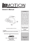
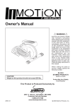
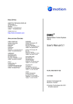
Contents
Warning and Caution…………………………………. 2
Warranty……………………………………………… 3
Important Information Before You Start……………... 4
Precautions……………………………………………. 5
Emergency Procedures………………………….…….. 5
Specification…………………………………………... 6
Transmitter Overview…………………………….…… 7
Receiver Overview……………………………………. 8
General Operation…………………………………….. 9
Getting Started…………………………………. 9
Transmitter LED Indicator…………………….. 10
Changing Receiver Input Voltage……………... 11
Frequency Chart………………………………………. 12
Installation Notes……………………………………… 13
Receiver Wiring Diagram……………………………... 14
1
Warning and Caution
The following symbols may be found on the product or
throughout the documentation.
Symbol Description
Refer to Manual
Refer to the user manual for additional information
when marked with this sign.
Dangerous Voltage
Indicates the presence hazardous voltage. Unsafe
practice could result in severe personal injury.
Warning
Denotes a hazard. Included text gives proper
procedures. Failure to follow instructions could
result in severe personal injury and/or property
damage.
Caution
Denotes a hazard. Included text gives proper
procedures. Failure to follow instructions could
result in minor personal injury and/or property
damage.
2
FCC ID: NCT081K IC: 2802A-081K
CE 0470
WARRANTY
INMOTION Controls, Inc. guarantees that this product meets its published
specification at the time of shipment from the factory. Under proper installation, it
should work as expected. However, INMOTION Controls, Inc. does not guarantee
that operation of the 342 Series Radio Control System is error-free or without
interruption.
This equipment is warranted against defects in materials and workmanship for a
period of one year from the date of shipment. During the warranty period,
INMOTION Controls, Inc. is responsible for necessary repairs, as long as the
product can be proved to be defective.
For warranty service or repair, this product must be returned to our factory.
Customer is responsible for shipping charges to INMOTION Controls, Inc., while
INMOTION Controls, Inc. will pay return shipping charges.
This warranty does NOT include consumable parts, such as joystick, batteries,
fuses, buttons, and relays or damage from normal wear and tear. Furthermore, this
warranty does NOT cover defects caused by misuse, neglect, accident, failure to
follow instructions, improper installation, improper or insufficient maintenance,
unauthorized modification, unsuitable operating environment, improper operation,
ignorance of environmental specifications, improper software/interfacing, fire, or
acts of God.
• No other warranty is expressed or implied, except for the above
mentioned
• The remedies provided herein are the buyers’ sole and exclusive
remedies.
• INMOTION Controls, Inc. shall not be liable for any direct/indirect,
special, incidental or consequential damages.
3
Important Information
Before You Start
1. Read this manual carefully before operating and installation.
2. Due to the complex nature of equipment, it is necessary to read
the entire manual prior to installation.
3. Never allow any unauthorized personnel to dismantle
equipment as this may cause damage to the equipment.
4. The equipment has been stringently tested for quality assurance
before delivery from factory. However, it must not be used in
extremely dangerous situations, or where damage may result.
5. After operation, switch off crane main power as well as
receiver unit and remove the rotary key from the transmitter
unit.
6. Keep the transmitter in a safe place when not in use to avoid
any unintentional operation.
7. The crane should be equipped with a main power relay, limit
switches and other required safety devices.
8. Do not use this device during an electrical storm or where there
are conditions of high electrical interference/
9. Always check transmitter battery and receiver input power
condition before operation.
10.The installation and maintenance service is allowed only when
the crane and receiver power are off to avoid electric shock.
11. The contents of the manual may be amended by the
manufacturer without notice.
12. The specification and function is subject to change without
notice by manufacturer.
4
.
Precautions
1. Press EMO (Emergency Off) button and switch off main
power of crane and receiver after operation. Then remove
transmitter rotary key and keep in a safe place.
2. The following situations may cause a receiver response
delay. You should stop operation immediately if these
situations occur.
(a) If you go beyond the operating range.
(b) During severe radio interference.
3. Remove transmitter batteries when not used for a long
period of time.
4. To extend product life, please follow the standard operating
procedure and maintain system regularly.
5. Check EMO button and other system main functions before
operation.
6. Press EMO button during system failure or any abnormal
conditions occur.
7. The operator must be familiar with emergency procedures
before operating the system.
.
Emergency Procedures
In case of emergency, please follow the procedure below:
1. Press EMO button and stop operation.
2. Switch the rotary key to “OFF” position and remove
it from transmitter unit.
3. Switch off crane main power.
4. Contact an authorized distributor for further assistance.
5
Specification
General Specification
ID Code……………………………..
Channel Space………………………
Hamming Distance………………….
Structure…………………………….
Operating Environment……………..
Operating Distance………………….
Over 1 Million Sets
25 KHz
>4
Enhanced Glass-Fiber
-40°F ~ +185°F
Up to 300 Feet
Transmitter
Power…………………………….
Emission Power………………….
Dimensions………………………
Weight……………………………
(4) AA Alkaline Batteries
<10mW
6.42” x 1.93” x 1.77”
0.463 lbs.
Receiver
Power………………………….. 24/48/110/220VAC (±20%)
Dimensions……………………. 6.57” x 6.06” x 3.46”
Weight…………………………. 4.63 lbs.
6
Transmitter Overview
Inmotion Series 342 Transmitter Overview
7
Receiver Overview
Inmotion Series 342 Receiver Overview
8
General Operation
Getting Started
1. Install 4 new AA-size batteries in the battery compartment
(make sure batteries are correctly installed according to
“Positive” & “Negative”) and close the battery cover
firmly.
2. Insert rotary key into transmitter unit and switch to “ON”
position.
3. Press START button to power on the system.
Note: Red LED indicator will flash if this procedure is
not followed accordingly.
4. Press function button for operation.
Follow the procedure below when finished with operation.
1.
2.
3.
4.
Press EMO button.
Switch rotary key to “OFF” position.
Remove rotary key and keep in a safe place.
Remove batteries if not to be used for a long
period of time.
9
Transmitter LED Indicator
Green (Full Power)
Yellow (Mid Power)
Red (Low Power)
Operate as usual.
Unload the article as soon as
possible and stop operation until
old batteries are replaced with
fresh batteries.
An EMS signal will be sent to
the receiver automatically to
turn off receiver. To avoid
interruption during operation,
check battery power frequently.
10
Receiver Voltage Selection
There are two types of power voltages (DC and AC) available
for the Series 342.
1) DC Type:
Input Voltage: 12~24 VDC
Relay Contact: 6.7A-36 VDC
2) AC Type:
Three different AC transformers:
48/110/220V, 48/220/380V, 110/220/380V.
Please disconnect the Receiver’s power, select the proper
voltage, and plug in the connector. See picture below.
Note: Standard Systems are 48/110/220 VAC. If any others are
required, please specify when ordering.
11
FREQUENCY CHART
Ch
Freq. MHz
Ch
Freq. MHz
Ch
Freq. MHz
Ch
Freq. MHz
1
2
3
4
5
6
7
8
9
10
11
12
13
14
15
16
17
18
19
20
433.050
433.075
433.100
433.125
433.150
433.175
433.200
433.225
433.250
433.275
433.300
433.325
433.350
433.375
433.400
433.425
433.450
433.475
433.500
433.525
21
22
23
24
25
26
27
28
29
30
31
32
33
34
35
36
37
38
39
40
433.550
433.575
433.600
433.625
433.650
433.675
433.700
433.725
433.750
433.775
433.800
433.825
433.850
433.875
433.900
433.925
433.950
433.975
434.000
434.025
41
42
43
44
45
46
47
48
49
50
51
52
53
54
55
56
57
58
59
60
434.050
434.075
434.100
434.125
434.150
434.175
434.200
434.225
434.250
434.275
434.300
434.325
434.350
434.375
434.400
434.425
434.450
434.475
434.500
434.525
61
62
63
64
65
66
67
68
69
70
433.550
433.575
433.600
433.625
433.650
433.675
433.700
433.725
433.750
433.775
12
Installation Notes
13
Receiver Wiring Diagram
14