1
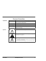
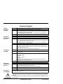
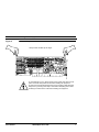
User’s Manual PE5000(D)HX Series SBC 23623C June 1998 © Texas Micro Inc. All Rights Reserved Printed in USA Limited Warranty A. Texas Micro Inc. warrants that the item sold by it hereunder will be free from defects in materials or workmanship, under normal use and service, for a period of 2 years from date of shipment. Said item will meet the specifications in effect at the time of manufacture. Texas Micro's sole obligation under this warranty shall be, at its option, to repair or replace, without charge, any defective component of said item, within a reasonable period of time. B. Texas Micro Inc. shall not be liable under this warranty for (i) the item that the Buyer alleges to be defective and was repaired or altered by someone other than Texas Micro's designated personnel or authorized representative, unless such repair or alteration was effected pursuant to prior written approval of Texas Micro, or (ii) where the Buyer fails to notify Texas Micro of any alleged defect within the period of warranty, or (iii) where the Buyer fails to return the allegedly defective item to Texas Micro Inc., in Houston, Texas, USA, freight prepaid, or (iv) where the item was altered or damaged in a way which Texas Micro reasonably determines to affect the performance and reliability of the item, or (v) where the item was subject to misuse, neglect, or accident. The rights and remedies granted to the Buyer under this paragraph constitute the Buyer's sole and exclusive remedy against Texas Micro Inc., its officers, agents, and employees, for negligence, inexcusable delay, breach of warranty, express or implied, or any other default relating to the item or Texas Micro's duties to eliminate any errors. This warranty supersedes any other warranty, whether expressed, implied, or statutory, including but not limited to any warranty for fitness of purpose, merchantability, or freedom from infringement or the like, and any warranty otherwise arising out of any proposal, specifications, or sample. Furthermore, Texas Micro Inc. neither assumes nor authorizes any person to assume for it any other liability. The software included with this equipment is warranted only in accordance with the terms of its license agreement. Except as warranted in that license agreement, the manufacturer of the software disclaims all warranties and conditions with regard to the software, including all implied warranties and conditions of merchantability, fitness for a particular purpose, title, and non-infringement. Every effort has been made to ensure that the information provided in this manual is complete and accurate. However, technical inaccuracies or typographical errors may be inadvertently included. Texas Micro assumes no responsibility for any errors that may be contained in this document. Texas Micro makes no promise to update or keep current the information contained in this document. Information in this document, including product specifications, is subject to change without notice. Any rights not expressly granted herein are reserved. All tradenames referenced are the service mark, trademark, or registered trademark of the respective manufacturer. i PE5000(D)HX Series SBC User’s Manual Important Always use caution when handling or operating the system. Only qualified and experienced electronics service personnel should access the unit’s interior. Use extreme caution when installing or removing components. If you have any questions, please contact Texas Micro Technical Support at (800) 627-8700 or (713) 541-8200 Monday through Friday between 7:00 a.m. and 6:00 p.m., Central Time, Continental USA. A Lire Imperativement Quand vous manipulez ou utilisez la système, faites preuve en toutes circonstances de la plus grande prudence. Seuls des techniciens électroniciens qualifiés et expérimentés peuvent avoir accès à l’intérieur de la système. Si vous désirez poser des questions complémentaires, n’hésitez pas à prendre contact avec le Département d’assistance technique de Texas Micro au (USA) 1-713-541-8200. Bitte Zuerst Lesen Seien Sie immer vorsichtig, wenn Sie mit Ihrem System umgehen oder es bedienen. Nur qualifiziertes, erfahrenes Personal fär Elektronik sollte am Inneren des Gerätes arbeiten. Für Ihre Sicherheit sind Hinweise zur Vorsicht, Win Sie irgenwelche Fragen haben, setzen Sie sich bitte nit der Abteilung fr technische Unterstützung von Texas Micro unter der Rufnummer (USA) 1-713-541-8200 in Verbindung. Changes or modifications not expressly approved by Texas Micro Inc. could void the product warranty and the user's authority to operate the equipment. User’s Manual PE5000(D)HX Series SBC ii Notice This equipment has been tested and found to comply with the limits for a Class A digital device, pursuant to Part 15 of the FCC Rules. These limits are designed to provide reasonable protection against harmful interference when the equipment is operated in a commercial environment. This equipment generates, uses, and can emit radio frequency energy and, if not installed and used in accordance with this instruction manual, may cause harmful interference to radio communications. Operation of this equipment in a residential area is likely to cause harmful interference, in which case, the user will be required to correct the interference at the user's expense. This device complies with Part 15 of the FCC Rules. Operation is subject to the following conditions: • This device may not cause harmful interference • This device must accept any interference received, including interference that may cause undesired operation Any change or modification not expressly approved by the manufacturer is prohibited and could void the user's authority to operate the equipment. This product also meets requirements for compliance with EN55022, Class B ITE. iii PE5000(D)HX Series SBC User’s Manual Document Conventions Typography Title Case Bold Title Case Titles of menus, windows, tabs, lists, and groups. Names of menu items, fields, buttons, icons, check boxes, list items, group items, and keystrokes. UPPER CASE Acronyms and abbreviations. Italics Emphasis. Sans Serif Type Items in tables, illustrations, and notations. Monospace Type Output from a printer or monitor. Graphic items will be displayed as an image. Symbols Caution: indicates an item for special consideration. ! ! Warning: indicates a hazard that can cause personal injury and/ or damage to the equipment. High Voltage: indicates one or both of the following: • • User’s Manual The presence of a high electrical current that can cause personal injury and/or damage to the equipment Electronic parts that can be damaged by electrostatic discharge (ESD) PE5000(D)HX Series SBC iv Customer Support Calling Technical Support Step 1 2 3 Returning Products for Service Step 1 2 3 4 Accessing the BBS Step 1 2 3 Using the InfoLine Fax Service Step 1 2 3 Accessing the Website ! v Action Have the Texas Micro product model and serial number available. • In the Continental USA, Monday — Friday, 7:00 a.m. — 6:00 p.m., Central Time, dial 1-800-627-8700 in the USA. Outside the USA, dial 713-541-8200 (add long distance/international access codes). • In Europe, Monday — Friday, 8:00 a.m. — 6:00 p.m., dial +31-36-5365595. Upon answer, press 3 for Technical Support. Action Have the Texas Micro product model and serial number available. • In the Continental USA, Monday — Friday, 7:00 a.m. — 6:00 p.m., Central Time, dial 1-800-627-8700 inside the USA. Outside the USA, dial 713-541-8200 (add long distance/international access codes). • In Europe, Monday — Friday, 8:00 a.m. — 6:00 p.m., dial +31-36-5365595. Upon answer, press 3 for Technical Support. When you are assigned a Returned Goods Authorization (RGA) number from a Technical Support Representative, place it, along with the product serial number, on the packaging materials and correspondence. The factory will be unable to accept delivery without these numbers. Note: The factory does not accept RGA's sent freight collect. Action 24 hours a day, 7 days a week, dial 713-541-8250 (add long distance/international access codes). Set your modem/communications equipment to: Protocol: ANSI Data Bits: 8 Parity: None Stop Bits: 1 Note: Refer to your modem and communication software documentation for configuration and operation instructions. When you connect, follow the online instructions to download software. Action 24 hours a day, 7 days a week, dial 713-541-8200 or 800-627-8700 (add long distance/international access codes). Note: You can use this service only with a touch-tone telephone. Upon answer, press 190 for the InfoLine fax service. Follow the instructions to request documents. http://www.texasmicro.com Upon receiving your equipment, inspect the packaging, shipping materials, and contents. If damaged, return the equipment to Texas Micro Inc. in the original packaging and shipping materials. If you are satisfied with your equipment, retain the packaging and shipping materials in case of future need. PE5000(D)HX Series SBC User’s Manual Table of Contents Chapter 1 Introduction 1 PE5000(D)HX Series SBC ................................................................................ 2 Chapter 2 7 Steps to Operation 5 Handling the PE5000(D)HX............................................................................... 6 Step 1: Check Jumper Settings ......................................................................... 8 Step 2: Check Switch Settings......................................................................... 10 Step 3: Install the SBC..................................................................................... 12 Step 4: Attach Peripherals to Headers ............................................................ 14 Step 5: Attach Peripherals to Connectors........................................................ 16 Step 6: Power-On the System ......................................................................... 18 Step 7: Run the Setup Utility............................................................................ 20 Chapter 3 Technical Data 27 Specifications................................................................................................... 28 Pin Signals....................................................................................................... 30 Installing Memory............................................................................................. 34 User’s Manual PE5000(D)HX Series SBC vi List of Figures 1 2 3 4 5 6 7 8 9 10 11 12 13 vii PE5000(D)HX Components and Layout............................................................................. 3 Safely Handling the SBC .................................................................................................... 7 Jumper Block Locations ..................................................................................................... 9 Switch Block Location....................................................................................................... 11 Installing the SBC ............................................................................................................. 13 Peripheral Header Locations ............................................................................................ 15 Peripheral Connector Locations ....................................................................................... 17 Setup Utility Main Menu.................................................................................................... 19 The PE5000(D)HX Series SBC ........................................................................................ 29 Serial and Parallel Headers and Connectors ................................................................... 31 Peripheral Headers and Connectors ................................................................................ 33 Memory Sockets............................................................................................................... 35 Memory Combinations...................................................................................................... 35 PE5000(D)HX Series SBC User’s Manual Introduction This chapter discusses the primary features of the PE5000(D)HX. If you are familiar with the primary components and functions of the PE5000(D)HX, and you wish to quickly begin operating the SBC, go to Chapter 2, “7 Steps to Operation,” page 5. Then read this chapter later at your convenience. User’s Manual PE5000(D)HX Series SBC 1 Introduction PE5000(D)HX Series SBC Overview The Texas Micro PE5000(D)HX Single Board Computer (SBC) provides the following features: • 100/133/166 MHz Intel™ Pentium® processor (P54C) More... 2 ! Use of a Pentium processor with MMX™ technology (P55C) can cause damage to the equipment and could void the warranty. • • • • • • • • • Intel 82439HX System Controller (TXC) • • • • • • Floppy drive controller Intel 82374SB EISA System Component (ESC) Intel 82375SB PCI EISA Bridge (PCEB) Intel 82091AA Advanced Integrated Peripheral (AIP) 2 Mb (256 KB x 8) flash memory 1 Mb (128 KB x 8) auxiliary BIOS Dallas DS1387 Real Time Clock with 4 KB x 8 extended RAM Level 2 write-back cache socket for 256 or 512 KB pipeline burst COAST SRAM Four (4) SIMM sockets for up to 256 MB scaleable DRAM Note: The PE5000HX supports FPM or EDO, x36 or x32. IDE drive controller Two (2) serial ports (one RS-232 only; one RS-232 or RS-422) Parallel port (AT-compatible/bi-directional) PS/2 mouse connector PS/2 keyboard connector For more information on the components of the PE5000(D)HX, contact: Company Telephone Website Intel Corporation Standard Microsystems Corporation PCI Special Interest Group PICMG (602) 554-8080 (516) 435-6000 (503) 696-2000 (781) 246-9318 http://www.intel.com http://www.smsc.com http://www.pcisig.com http://www.picmg.com PE5000(D)HX Series SBC User’s Manual PE5000(D)HX Features Figure 1 PE5000(D)HX Components and Layout D E 2 3 4 N 5 6 7 B J I 8 K 9 L F A G 10 H M 1 C A. B. C. D. E. F. G. H. I. J. K. L. M. N. Primary Pentium Processor Secondary Pentium Processor Pentium Processors with Heatsinks Level 2 SRAM Cache Socket DRAM SIMM Sockets Intel 82439HX System Controller (TXC) Intel 82374SB EISA System Component (ESC) Intel 82375SB PCI EISA Bridge (PCEB) Speaker Intel 82091AA Advanced Integrated Peripheral (AIP) Dallas DS1387 Real Time Clock Flash Device Auxiliary BIOS DIP Switch Block User’s Manual 1. Keyboard Header 2. IDE Activity LED Header 3. IDE Header (Primary Controller) 4. Floppy Drive Header 5. Serial Port 1 Header 6. Serial Port 2 Header 7. I/O Bracket 8. PS/2 Mouse 9. PS/2 Keyboard 10. Parallel Port Connector PE5000(D)HX Series SBC 3 Introduction Notes 4 PE5000(D)HX Series SBC User’s Manual 7 Steps to Operation This chapter describes basic precautions for handling the PE5000(D)HX. This chapter then outlines the basic steps for setting up the SBC: 1. Check jumper settings 2. Check switch settings 3. Install the SBC 4. Attach peripheral devices to headers 5. Attach peripheral devices to connectors 6. Power-on the system 7. Run the Setup Utility User’s Manual PE5000(D)HX Series SBC 5 7 Steps to Operation Handling the PE5000(D)HX Overview This section suggests basic precautions when handling the PE5000(D)HX series SBC. Static Electricity The PE5000(D)HX is designed to protect against ESD (electro-static discharge) and excessive voltage. However, excessive static electricity can damage components. Before you handle the SBC, use the grounding wrist strap provided with the system to discharge static electricity. Instructions for using the wrist strap are printed on the strap's envelope. Always handle the SBC by the edges to help prevent accidental damage that can be caused by static discharge (Figure 2). Safety It is important to protect yourself and your equipment before you perform any of the procedures outlined in this manual. You should check the configuration before you install the SBC. If the SBC is already installed in your system and you need to change the configuration, power-off the system and disconnect all power cords from their source. Follow all safety precautions as outlined by the chassis manufacturer. To avoid damage or injury, always power-off the system and disconnect all power cords from their power source before handling the equipment. To help prevent accidental damage that can be caused by static discharge, always use a grounding wrist strap or other static-dissipating device when accessing the interior of the chassis and handling the equipment. ! Next... Only qualified, experienced electronics personnel should access the interior of the chassis and handle the equipment. Before you install the SBC in a chassis, check the following: • Jumper settings, outlined in Step 1, page 8 • DIP switch settings, outlined in Step 2, page 10 Pay particular attention to the switch settings. The jumper settings are preconfigured at the factory and are appropriate for most applications. 6 PE5000(D)HX Series SBC User’s Manual Handling the PE5000(D)HX Figure 2 Safely Handling the SBC Always handle the SBC by the edges. To avoid damage or injury, always power-off the system and disconnect all power cords from their power source before handling the equipment. To help prevent accidental damage that can be caused by static discharge, always use a grounding wrist strap or other static-dissipating device when accessing the interior of the chassis and handling the equipment. User’s Manual PE5000(D)HX Series SBC 7 7 Steps to Operation Step 1: Check Jumper Settings Overview Before you install the PE5000(D)HX onto a passive backplane in a chassis, check the jumper settings on the SBC (Figure 3). Definition A Jumper is a small "bridge" that connects two pins on a Jumper Block. The position of a jumper affects the device's operational parameters. Jumper Blocks The PE5000(D)HX contains: • Four (4) two-pin jumper blocks (JP1, JP2, JP8, and JP9) • Five (5) three-pin jumper blocks (JP3, JP4, JP5, JP6, and JP7) Settings Settings for the jumper blocks are provided in the following tables: 2-Pin Jumper Blocks JP1 JP2 Bus/Core Ratio† CPU Speed None None 2/3 100 MHz 1—2 None 1/2 133 MHz 1—2 1—2 2/5 166 MHz †The Bus Core Ratio is based on the Host Bus Speed at 66.6MHz. JP8 None 1—2 1—2 JP9 1—2 None 1—2 JP3 1—2 2—3 JP4 1—2 2—3 JP5 1—2 2—3 8 JP6 1—2 2—3 Host Bus Speed 66.6 MHz (default) 60.0 MHz 50.0 MHz 3-Pin Jumper Blocks Watchdog Timer Active (default) Inactive Next Step OS Operation Use this setting when running Next Step OS and experiencing problems with PS/2 mouse Other OS (default) JP7 1—2 2—3 PE5000(D)HX Series SBC Serial 2 Configuration RS-422 RS-232 (default) User’s Manual Step 1: Check Jumper Settings Figure 3 Jumper Block Locations JP5 JP8 JP6 JP7 JP9 JP3 JP1 JP2 JP4 2-Pin 3-Pin Jumpers JP1, JP2 JP8, JP9 JP3 JP4 JP5, JP6, JP7 Function CPU Speed Host Bus Speed Watchdog Timer Next Step OS Operation Serial 2 Configuration To avoid damage or injury, always power-off the system and disconnect all power cords from their power source before handling the equipment. To help prevent accidental damage that can be caused by static discharge, always use a grounding wrist strap or other static-dissipating device when accessing the interior of the chassis and handling the equipment. User’s Manual PE5000(D)HX Series SBC 9 7 Steps to Operation Step 2: Check Switch Settings Overview After you check the jumper settings, check the switch block on the PE5000(D)HX for proper settings (Figure 4). Switch Block The switch block contains four (4) DIP switches that you can configure to affect the following items: • • • • Settings Default monitor type On-board ROM access CMOS RAM Configuration ports Settings for the switches are provided in the following table: SW1-1 SW1-2 SW1-3 SW1-4 ! 10 Default Monitor Type Open Monochrome monitor Closed (default) Color monitor On-Board ROM Access Open (default) Flash memory enabled; Auxiliary ROM disabled Closed Flash memory disabled; Auxiliary ROM enabled CMOS RAM Open (default) Normal operation of CMOS RAM Closed Factory default values for the Setup Utility are loaded into CMOS RAM Configuration Ports Open (default) Configuration ports are mapped to I/O address 270/271 Closed Configuration ports are mapped to I/O address 370/371 The system will not operate without Memory Bank 0 (SIMM’s 1 and 2) filled. For more information on Memory Modules, see page 34. PE5000(D)HX Series SBC User’s Manual Step 2: Check Switch Settings Figure 4 Switch Block Location Top View of Switch Block Closed Open 1-4 1-3 1-2 1-1 To avoid damage or injury, always power-off the system and disconnect all power cords from their power source before handling the equipment. To help prevent accidental damage that can be caused by static discharge, always use a grounding wrist strap or other static-dissipating device when accessing the interior of the chassis and handling the equipment. User’s Manual PE5000(D)HX Series SBC 11 7 Steps to Operation Step 3: Install the SBC Overview Before you connect any peripheral devices to the PE5000(D)HX, install the SBC onto a passive backplane in a chassis (Figure 5). Procedure The procedure for installing the SBC is outlined in the following table: Step 1 Action Power-off the system and disconnect all power cords. Note: Use the grounding wrist strap provided with the system to discharge static electricity. 2 Remove the chassis cover. 3 Detach the circuit card hold-down bracket (if required). This bracket reaches across the tops of the circuit cards and holds them in place. 4 Locate the EISA/PCI CPU slot on the passive backplane. Note: The SBC will not function if it is installed in the improper slot. 5 Remove the I/O blank bracket from the rear of the chassis (if required). This blank bracket occupies the area where the SBC’s I/O bracket is accessed from the rear of the chassis. 6 Insert the SBC into the chassis with the card edge aligned in the card-end slot and the I/O bracket in the chassis I/O slot. Lower the SBC to the “Platform” or “CPU” slot on the backplane. Carefully push the SBC connectors into the slot on the backplane. Ensure that the I/O bracket is accessible through the rear of the chassis. 7 Secure the I/O bracket to the fastening lip on the chassis. Note: To install the PE5000(D)HX onto a passive backplane not manufactured by Texas Micro, follow the instructions provided by the manufacturer. ! ! 12 If the SBC is installed into a chassis not manufactured by Texas Micro, a custom cable might be needed to adapt the keyboard header to the wiring in the chassis. Texas Micro does not provide such a cable.. The SBC requires a minimum airflow of 200 linear feet per minute (LFM) unimpeded across the CPU within 0 to 60 °C (32 to 140 °F) ambient temperature. Operations outside these specifications could void the warranty. PE5000(D)HX Series SBC User’s Manual Step 3: Install the SBC Figure 5 Installing the SBC Front of Chassis Rear of Chassis Card-End Slot "Platform" or "CPU" Slot Passive Backplane PCI Bus EISA Extension EISA Bus Bottom of Chassis To avoid damage or injury, always power-off the system and disconnect all power cords from their power source before handling the equipment. To help prevent accidental damage that can be caused by static discharge, always use a grounding wrist strap or other static-dissipating device when accessing the interior of the chassis and handling the equipment. User’s Manual PE5000(D)HX Series SBC 13 7 Steps to Operation Step 4: Attach Peripherals to Headers Overview After you have installed the PE5000(D)HX onto a passive backplane in a chassis, attach the necessary peripheral devices to the appropriate headers on the SBC (Figure 6). IDE Drive Two (2) IDE devices can be attached to this header via a 40-conductor flat cable. Note: The "red stripe" on the cable should be near Pin 1 on the header. ! The BIOS will support up to four (4) IDE drives. To use 3 or 4 drives, a 2nd controller is required. The 2nd controller must be configured to use IRQ15 and I/O Ports 170-177h. IDE Activity LED This header connects the IDE activity LED cable to the SBC. Note: Pin 1 is the anode (+V); Pin 2 is the cathode (-V). FDD Two (2) floppy disk drives can be attached to this header via a 34-conductor flat cable. Note: The "red stripe" on the cable should be near Pin 1 on the header. Serial Ports A serial device can be attached to each serial header (16550-compatible) via a 10-conductor flat cable. If connecting a serial mouse, be sure to use a shielded cable. Note: The "red stripe" on the cable should be near Pin 1 on the header. ! Keyboard 14 Improperly connecting the cable to these headers can cause damage to the cable, SBC, and external serial device, and could void the warranty. An AT or PS/2 keyboard can be attached to this header with an appropriate 8-pin cable. Note: The sockets on the Texas Micro keyboard header cable are numbered in reverse order when compared to the pinout of the keyboard header on the SBC. PE5000(D)HX Series SBC User’s Manual Step 4: Attach Peripherals to Headers Figure 6 Peripheral Header Locations 2 3 4 5 6 1 1. Keyboard 2. IDE Activity LED 3. IDE Drive 4. Floppy Drive 5. Serial Port 1 6. Serial Port 2 To avoid damage or injury, always power-off the system and disconnect all power cords from their power source before handling the equipment. To help prevent accidental damage that can be caused by static discharge, always use a grounding wrist strap or other static-dissipating device when accessing the interior of the chassis and handling the equipment. ! User’s Manual For pin signals and positions, see page 30. PE5000(D)HX Series SBC 15 7 Steps to Operation Step 5: Attach Peripherals to Connectors Overview After you have attached peripheral devices to the headers on the PE5000(D)HX, attach devices to the connectors on the SBC (Figure 7). To avoid damage or injury, always power-off the system and disconnect all power cords from their power source before connecting or disconnecting any cables for the SBC. Mouse A PS/2 mouse can be attached to this connector. Keyboard A PS/2 keyboard can be attached to this connector. Parallel Port The IEEE 1284 parallel port: • Is a DB-25 female connector • Provides a Centronics-compatible printer interface • Supports AT-compatible and bi-directional operations 16 PE5000(D)HX Series SBC User’s Manual Step 5: Attach Peripherals to Connectors Figure 7 Peripheral Connector Locations 1 2 3 4 1. I/O Bracket 2. PS/2 Mouse 3. PS/2 Keyboard 4. Parallel Port To avoid damage or injury, always power-off the system and disconnect all power cords from their power source before handling the equipment. To help prevent accidental damage that can be caused by static discharge, always use a grounding wrist strap or other static-dissipating device when accessing the interior of the chassis and handling the equipment. ! User’s Manual For pin signals and positions, see page 30. PE5000(D)HX Series SBC 17 7 Steps to Operation Step 6: Power-On the System Overview After you have installed the PE5000(D)HX and connected all devices, power-on the system. No Power If the system does not power-on, check all power connections and the power source. If power connections are secure and the power source is adequate, contact Technical Support at (800) 627-8700 or (713) 541-8200 between 7:00 a.m. and 6:00 p.m., Central Time, USA. For more information, see “Customer Support,” page v. Startup After you power-on the system, it will: • Execute the Power-On Self Test (POST) to ensure that the system is functional and properly configured • Start the operating system Setup During the POST, you can access the Setup Utility (Figure 8) to configure the system. ! 18 Before using the SBC for the first time, you should verify the system settings in the Setup Utility. See page 20. PE5000(D)HX Series SBC User’s Manual Step 6: Power-On the System Figure 8 Setup Utility Main Menu ! " # $%&#''#(%) *+ ,# $'-.%/.%//&) ,0 # $%11 234) 5678 59!:678 ,0 # $,6) 5 7 ! , ' $;# <1( 6) , ' $=) , % $=) , % $=) > $? . >?) ;9 9@ A = 0# $A!!) # B1' C # & DEF G% " ↑ ↓ :.H ;9I > G/ ,! ←→ 6: G%' J > ; User’s Manual PE5000(D)HX Series SBC 19 7 Steps to Operation Step 7: Run the Setup Utility Overview The BIOS (Basic Input/Output System) Setup Utility allows you to configure the operations of the PE5000(D)HX. Access To access the Setup Utility, press F2 when prompted during the Power-On Self Test (POST). Display The Setup Utility display (Figure 8) contains two areas: 1. Options: The options for the current menu are on the left side of the screen 2. Item Specific Help: Instructions for the current item are on the right side Menus The Setup Utility contains a toolbar at the top of the screen that allows you to access the following menus: • • • • • • Main Advanced Security Boot Server Exit Options and items for these menus are listed in the tables beginning on page 21. Boot and Exit The Boot and Exit menus do not have “default” values. Items for these menus are not included in the tables below. Operation Use the following keys to operate the Setup Utility: Key Action Up Arrow ( ↑ ) and Down Arrow ( ↓ ) Select a menu item Left Arrow ( ← ) and Right Arrow ( → ) Select a menu Plus ( + ) and Minus ( - ) Change the value of an item Enter Access a sub-menu (when an item with the sub-menu character is highlighted) F1 Access Help for the Setup Utility F9 Load default values for the setup options F10 Cancel the changes you have made and load the previous values for the setup options Esc Access the Exit menu 20 PE5000(D)HX Series SBC User’s Manual Step 7: Run the Setup Utility Main Menu The options and item values for the Main menu are listed in the table below: Option / Sub-Menu System Time Item N/A System Date N/A Diskette A N/A Diskette B N/A IDE Adapter 0/1 Master/Slave Type Cylinders Heads Sectors/Track Write Precomp Multi-Sector Transfers Video System Memory Cache Memory Shadow Boot Options User’s Manual LBA Mode Control 32-Bit I/O Transfer Mode N/A External Cache Cache System BIOS Area Cache Video BIOS Area Cache C800—DFFF System Shadow Video Shadow Regions with Legacy Expansion ROMs Summary Screen Floppy Check Quiet Boot (Graphic) POST Errors Default Setting Alternate Settings Current Time in Hours, N/A Minutes, and Seconds Current Date in Month, Day, N/A and Year 1.44 MB 3½” Not Installed, 720 KB 3½”, 2.88 MB 3½”, 360 KB 5¼”, 1.2 MB 5¼” Not Installed 720 KB 3½”, 1.44 MB 3½” 2.88 MB 3½”, 360 KB 5¼”, 1.2 MB 5¼” Auto (All 4 IDE devices) None, User, 1-39, CD Note: If Type is set to Auto, the only option available is 32-Bit I/O. Enter a value N/A Enter a value N/A Enter a value N/A None N/A 16 Sectors Disabled, 2 Sectors, 4 Sectors, 8 Sectors Enabled Disabled Disabled Enabled Standard N/A EGA / VGA CGA 80x25, Monochrome Disabled Enabled Enabled Disabled Enabled Disabled Disabled (All regions) Enabled Enabled N/A Enabled Disabled ROM Shadow RAM Note: This feature is available only for ISA/EISA ROMs. Enabled Disabled Enabled Disabled Disabled Enabled Enabled Disabled PE5000(D)HX Series SBC 21 7 Steps to Operation Main The items for the Main menu are continued below: Option / Sub-Menu Keyboard Features Keyboard Auto-Repeat Delay N/A N/A System Memory Extended Memory Advanced 22 1/2 sec Display only Display only Alternate Settings On, Auto Disabled 26.7/sec, 21.8/sec, 18.5/sec, 13.3/sec, 10/sec, 6/sec, 2/sec 1/4 sec, 3/4 sec, 1 sec N/A N/A The options and item values for the Advanced menu are listed in the table below: Option / Sub-Menu Integrated Peripherals Advanced Chipset Control Item Default Setting Numlock Off Key Click Enabled Keyboard Auto-Repeat Rate 30/sec Item COM A Port (Serial 1) Default Setting 3F8 IRQ 4 (COM 1) COM B Port (Serial 2) 2F8 IRQ 3 (COM 2) LPT Port 278 IRQ 7 Diskette Controller Integrated IDE Adapter DRAM Speed Memory Gap Enabled Primary 70 ns Disabled Watchdog Timer Delay Onboard Speaker EISA PCI Latency ECC/Parity Config 1.2 sec On 3 uS Parity PE5000(D)HX Series SBC Alternate Settings 2F8 IRQ 3 (COM 2), 3E8 IRQ 4 (COM 3), 2E8 IRQ 3 (COM 4), 2E8 IRQ 4, 3E8 IRQ 3, 220 IRQ 4, 220 IRQ 3, 228 IRQ 4, 228 IRQ 3, 238 IRQ 4, 238 IRQ 3, 338 IRQ 4, 338 IRQ 3, Auto, Disabled 3F8 IRQ 4 (COM 1), 3E8 IRQ 4 (COM 3), 2E8 IRQ 3 (COM 4), 2E8 IRQ 4, 3E8 IRQ 3, 220 IRQ 4, 220 IRQ 3, 228 IRQ 4, 228 IRQ 3, 238 IRQ 4, 238 IRQ 3, 338 IRQ 4, 338 IRQ 3, Auto, Disabled 378 IRQ 7, 378 IRQ 5, 278 IRQ 5, Auto, Disabled Disabled Disabled 60 ns 512 KB — 640 KB, 15 MB — 16 MB 150 ms Off 1 uS, 2 uS, 4 uS Disabled, ECC User’s Manual Step 7: Run the Setup Utility Advanced The items for the Advanced menu are continued below: Option / Sub-Menu PCI Devices Item PCI IRQ Line 1 PCI IRQ Line 2 PCI IRQ Line 3 PCI IRQ Line 4 Use Multiprocessor Specification N/A PS/2 Mouse Plug & Play O/S Reset Configuration Data Large Disk Access Mode N/A N/A N/A N/A User’s Manual Default Setting Alternate Settings Disabled, Auto Select, 3 (COM2/COM4), 4 (COM1/COM3), 5 (2nd LPT), 7 (1st LPT), 10, 11 (Open), 12 (PS/2 Mouse), 14 (Primary IDE), 15 (Secondary IDE) Note: Incorrect settings may cause system malfunction. 10 Disabled, Auto Select, 3 (COM2/COM4), 4 (COM1/COM3), 5 (2nd LPT), 7 (1st LPT), 9, 11 (Open), 12 (PS/2 Mouse), 14 (Primary IDE), 15 (Secondary IDE) 11 Disabled, Auto Select, 3 (COM2/COM4), 4 (COM1/COM3), 5 (2nd LPT), 7 (1st LPT), 9, 10 (Open), 12 (PS/2 Mouse), 14 (Primary IDE), 15 (Secondary IDE) 15 Disabled, Auto Select, 3 (COM2/COM4), 4 (COM1/COM3), 5 (2nd LPT), 7 (1st LPT), 9, 10, 11 (Open), 12 (PS/2 Mouse), 14 (Primary IDE) 1.1 1.4 Note: This option must be set to 1.1 if Windows NT® 3.5x is used. Disabled Enabled No Yes No Yes DOS Other 9 PE5000(D)HX Series SBC 23 7 Steps to Operation Security The options and item values for the Security menu are listed in the table below: Option / Sub-Menu Supervisor Password Is Item N/A User Password Is N/A Set Supervisor Password Set User Password Password on Boot Diskette Access Fixed Disk Boot Sector System Backup Reminder Virus Check Reminder N/A N/A N/A N/A N/A N/A N/A Server Default Setting Disabled (Display only) Disabled (Display only) Enter a value Enter a value Disabled Supervisor Normal Disabled Disabled The options and item values for the Server menu are listed in the table below: Option / Sub-Menu Console Redirect Port Item N/A Default Setting Disabled Console Redirect Baud Rate N/A 9600 24 Alternate Settings Enabled (Display only) Enabled (Display only) N/A N/A Enabled User Write Protect Daily, Weekly, Monthly Daily, Weekly, Monthly PE5000(D)HX Series SBC Alternate Settings 3F8 IRQ 4 (COM 1), 2F8 IRQ 3 (COM 2), 3E8 IRQ 4 (COM 3), 2E8 IRQ 3 (COM 4), 3E8 IRQ 3, 2E8 IRQ 4, 338 IRQ 3, 338 IRQ 4, 238 IRQ 3, 238 IRQ 4, 228 IRQ 3, 228 IRQ 4, 220 IRQ 3, 220 IRQ 4, 19200, 38400, 56000 User’s Manual Step 7: Run the Setup Utility Notes User’s Manual PE5000(D)HX Series SBC 25 7 Steps to Operation Notes 26 PE5000(D)HX Series SBC User’s Manual Technical Data This chapter provides the following information: • System specifications and environmental tolerances • Pin positions and signal listings for all headers and connectors • Notes on installing memory modules User’s Manual PE5000(D)HX Series SBC 27 Technical Data Specifications Overview Listed in the table below are system specifications and environmental tolerances for the PE5000(D)HX series SBC. Note: These specifications are subject to change without notice. Environmental Environmental tolerances are listed in the following table: Temperature Note: See page 29. Humidity Shock Vibration Altitude System Operating: 0 to +60 °C (32 to 140 °F) Non-Operating: -40 to +70 °C (-40 to 158 °F) Operating: 5 — 95% @ 40 °C, non-condensing Non-Operating: 0 — 95% @ 40 °C, non-condensing Operating: 1 G @ 11 ms Non-Operating: 10 G @ 11 ms Operating: .5 G @ 5 — 200 Hz Non-Operating: 2 G @ 5 — 200 Hz Operating: 15,000 ft (4,572 m) Non-Operating: 50,000 ft (15,240 m) System specifications are listed in the following table: Single or Dual 100/133/166 MHz Intel™ Pentium® Processor (P54C) Intel 430HX and EISA Bridge PCIset 256 KB or 512 KB Level 2 write-back cache: Zero wait state at 66 MHz 8 ns synchronous pipeline burst COAST RAM Memory Four 72-pin sockets organized in two banks, supporting: Up to 256 MB 1/2/4/8/16 x 32/36, 60/70 ns, Fast Page Mode DRAM SIMM's Parity/FPM or Non-Parity ECC or EDO Single bit error correction, double bit detection (ECC mode only) Addressing Real and protected mode supported Real address mode: 20-bit Protected address mode: 16-bit on bus access Data Path 64-bit on board: 32-bit on EISA bus access, 32-bit on PCI local bus Flash Memory 2 Mb (256 KB x 8) Clock/Calendar DS1387 Real Time Clock accurate to +/- 12 minutes/year, at 25 °C; includes CMOS Power Requirements Input Power 35 — 45 W w/ 8 — 256 MB DRAM +5 V 7.0 — 9.0 A +12 V 0.1 A -12 V 0.1 A Form Factor 13.28" (33.73 cm) x 4.80" (12.19 cm) CPU Chipset Cache 28 PE5000(D)HX Series SBC User’s Manual Specifications Figure 9 The PE5000(D)HX Series SBC A Note on Thermal Specifications The technology and power density of the microprocessor is rapidly increasing. The 80386 required less than a few hundred milliamps of current. The 80486DX4 peaked at less than 1.5 A and typically dissipated less than 5 watts of power. The 233 MHz Pentium® processor with MMX™ technology requires up to 6.5 A and dissipates as much as 17 W. Power levels have finally increased to a level that greatly affects the ability of the equipment to effectively dissipate energy. Texas Micro is continually working to ensure that its products will conform to thermal specifications. However, we can only work within known or anticipated hardware and software configurations. One peripheral device installed within a chassis can significantly alter operating temperature. Also, software applications can cause as much as 20 °C variation. Even the cable layout within the chassis can affect airflow and thereby performance. Texas Micro validates the operating specifications of its products by testing with the “hottest” possible hardware and software configuration, that will maximize the power supply draw and generate a worst-case scenario. However, despite these efforts, the specifications are only benchmarks and should be regarded as such. ! User’s Manual The SBC requires a minimum airflow of 200 linear feet per minute (LFM) unimpeded across the CPU within 5 to 60 °C (41 to 140 °F) ambient temperature. Operations outside these specifications could void the warranty. PE5000(D)HX Series SBC 29 Technical Data Pin Signals Overview Pin 1 2 3 4 5 6 7 8 9 10 The tables below list the pin signals for the headers and connectors. The following illustration (Figure 10) indicates the pin positions for each. Serial Port 1 RS-232 Description Data Carrier Detect (In) Data Set Ready (In) Receive Data (In) Request to Send (Out) Transmit Data (Out) Clear to Send (In) Data Terminal Ready (Out) Ring Indicator (In) Ground +5V Pin 1 2 3 4 5 6 7 8 9 30 Serial Port 2 RS-232 RS-422 Pin Description Pin Description 1 Data Carrier Detect (In) DB9 10-Pin 2 Data Set Ready (In) 1 1 /Z Output (TX-) 3 Receive Data (In) 6 2 /B Receive (RX-) 4 Request to Send (Out) 2 3 Y Output (TX+) 5 Transmit Data (Out) 8 6 A Receive (RX+) 6 Clear to Send (In) 7 Data Terminal Ready (Out) 8 Ring Indicator (In) 9 Ground 10 +5V To connect two RS-422 devices, use a shielded twisted-pair (STP) cable no longer than 4,000 feet, configured as listed below: Machine A Machine B Pin Signal Pin Signal /Z Output (TX-) /B Receive (RX-) ←→ Y Output (TX+) A Receive (RX+) ←→ /B Receive (RX-) /Z Output (TX-) ←→ A Receive (RX+) Y Output (TX+) ←→ Description - Strobe Data Bit 0 Data Bit 1 Data Bit 2 Data Bit 3 Data Bit 4 Data Bit 5 Data Bit 6 Data Bit 7 Parallel Port Pin 10 11 12 13 14 15 16 17 18-25 Description - Acknowledge + Busy + Paper Feed + Select - Auto Feed - Error - Initialize Printer - Select Input Ground PE5000(D)HX Series SBC User’s Manual Pin Signals Figure 10 Serial and Parallel Headers and Connectors Serial Port 1 2 10 1 9 Serial Port 2 2 10 1 9 Parallel Port 1 14 25 13 To avoid damage or injury, always power-off the system and disconnect all power cords from their power source before handling the equipment. To help prevent accidental damage that can be caused by static discharge, always use a grounding wrist strap or other static-dissipating device when accessing the interior of the chassis and handling the equipment. User’s Manual PE5000(D)HX Series SBC 31 Technical Data Pin Signals Overview The tables below list the pin signals for each peripheral header. The following illustration (Figure 11) indicates the pin positions for each. IDE 32 Pin 1 3 4 5 6 7 8 9 10 11 12 13 14 15 16 17 18 20 Description Reset (Out) Data 7 (I/O) Data 8 (I/O) Data 6 (I/O) Data 9 (I/O) Data 5 (I/O) Data 10 (I/O) Data 4 (I/O) Data 11 (I/O) Data 3 (I/O) Data 12 (I/O) Data 2 (I/O) Data 13 (I/O) Data 1 (I/O) Data 14 (I/O) Data 0 (I/O) Data 15 (I/O) Not Connected Pin 1 2 3 4 5 6 7 8 Keyboard Description Reset Ground Not Connected Keyboard Clock Keyboard Data Keyboard Lock +5V Speaker Pin 21 23 25 27 28 29 31 32 33 34 35 36 37 38 39 2, 19, 22, 24, 26, 30, 40 Pin 1 2 3 4 5 6 Description DMA Request (In) - I/O Write (Out) - I/O Read (Out) I/O Channel Ready (In) + ALE DMA Acknowledge(Out) + IRQ14 (In) I/O CS16 (In) + ADDR1 (Out) Passed Diagnostics + ADDR0 (Out) + ADDR2 (Out) - CS0 (Out) - CS1 (Out) Activity Light (In) Ground PS/2 Mouse / Keyboard Description Data Not Connected Ground +5V Clock Not Connected PE5000(D)HX Series SBC User’s Manual Pin Signals Figure 11 Peripheral Headers and Connectors IDE HDD 2 1 40 39 2 FDD 34 IDE Activity LED + - 1 33 PS/2 Mouse 5 3 6 4 1 2 PS/2 Keyboard 8 5 3 6 4 1 2 Keyboard 1 Colored Trace Reset Ground Ground Keyboard Clock Keyboard Data Keyboard Lock +5V Out Speaker 1 8 To avoid damage or injury, always power-off the system and disconnect all power cords from their power source before handling the equipment. To help prevent accidental damage that can be caused by static discharge, always use a grounding wrist strap or other static-dissipating device when accessing the interior of the chassis and handling the equipment. User’s Manual PE5000(D)HX Series SBC 33 Technical Data Installing Memory Overview The PE5000(D)HX supports up to 256 MB of on-board dynamic RAM modules in FPM or EDO, x36 or x32. Note: The CPU supports ECC or Parity modes only if x36 modules are used. Memory Bank The PE5000(D)HX contains four (4) 72-pin SIMM sockets for DRAM memory modules (Figure 12). These four sockets comprise two (2) memory banks, each consisting of two sockets and providing a 64-bit wide data path and 8 parity bits (x36 SIMM's only): • Sockets 1 and 2 comprise Bank 0 • Sockets 3 and 4 comprise Bank 1 Bank 0 should be filled before Bank 1, and each bank must be completely filled to be operable. Also, both sockets in a bank must be filled with SIMM's of identical size. For example, if an 16MB SIMM is installed in Socket 1, another 16MB SIMM must be installed in Socket 2; otherwise, Bank 0 will be inoperable. SIMM Types Five SIMM memory sizes (4, 8, 16, 32, and 64 MB) are supported. SIMM’s of these sizes can be installed in sockets 1, 2, 3, or 4 in combinations as illustrated in Figure 13. Memory size is detected by the system BIOS. Memory timing requires 70 ns or faster page devices. Parity generation and checking is provided for each byte. ! 34 The SIMM sockets are gold and require gold SIMM's. Use of tin/lead SIMM's can cause damage to the equipment and could void the warranty. To avoid damage or injury, always power-off the system and disconnect all power cords from their power source before handling the equipment. To help prevent accidental damage that can be caused by static discharge, always use a grounding wrist strap or other static-dissipating device when accessing the interior of the chassis and handling the equipment. PE5000(D)HX Series SBC User’s Manual Installing Memory Figure 12 Bank 1 Bank 0 Memory Sockets SIMM 4 SIMM 3 SIMM 2 SIMM 1 Figure 13 L2 Cache Memory Combinations SIMM 1 & 2 SIMM 3 & 4 Empty 1 MB x 3X (4 MB) 1 MB x 3X (4 MB) 1 MB x 3X (4 MB) 2 MB x 3X (8 MB) Empty 1 MB x 3X (4 MB) 2 MB x 3X (8 MB) 2 MB x 3X (8 MB) 2 MB x 3X (8 MB) 4 MB x 3X (16 MB) Empty 1 MB x 3X (4 MB) 4 MB x 3X (16 MB) 4 MB x 3X (16 MB) 2 MB x 3X (8 MB) 4 MB x 3X (16 MB) 4 MB x 3X (16 MB) 8 MB x 3X (32 MB) Empty 1 MB x 3X (4 MB) 8 MB x 3X (32 MB) 8 MB x 3X (32 MB) 2 MB x 3X (8 MB) 8 MB x 3X (32 MB) 4 MB x 3X (16 MB) 8 MB x 3X (32 MB) 8 MB x 3X (32 MB) 16 MB x 3X (64 MB) Empty 1 MB x 3X (4 MB) 16 MB x 3X (64 MB) 16 MB x 3X (64 MB) 2 MB x 3X (8 MB) 16 MB x 3X (64 MB) 4 MB x 3X (16 MB) 8 MB x 3X (32 MB) 16 MB x 3X (64 MB) 16 MB x 3X (64 MB) 16 MB x 3X (64 MB) 3X = 36 for Parity, 32 for Non-Parity User’s Manual PE5000(D)HX Series SBC Total Memory 8 MB 16 MB 16 MB 24 MB 32 MB 32 MB 40 MB 48 MB 64 MB 64 MB 72 MB 80 MB 96 MB 128 MB 128 MB 136 MB 144 MB 160 MB 192 MB 256 MB 35 Technical Data Notes 36 PE5000(D)HX Series SBC User’s Manual