1
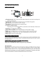
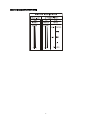
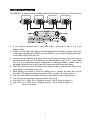
10W LED PIN SPOT
LED-PS10D W
User Manual
Professional Entertainment Technology
TABLE OF CONTENTS
1. Safety Instruction
2. Technical Specification
3. Installation
4. How to Control the Unit
4.1 Control Panel
4.2 Master/Slave operation
4.2 Easy controller
4.4 Universal DMX controller
5. DMX 512 Configuration
6. DMX 512 Connection
7. Trouble Shooting
8. Fixture Cleaning
1-
1. Safety Instruction
WARNING
Please read the instruction carefully which including
important information about the installation,
y Please keep this User Manual for future consultation. If you sell the unit to another
user, be sure that they also receive this instruction booklet.
y Unpack and check carefully there is no transportation damage before using the unit.
y Before operating, ensure that the voltage and frequency of power supply match the
power requirements of the unit.
y It’s important to ground the yellow/green conductor to earth in order to avoid electric
shock.
y The unit is for indoor use only and use only in a dry location.
y The unit must be installed in a location with adequate ventilation, at least 50cm from
adjacent surfaces. Be sure that no ventilation slots are blocked.
y Disconnect mains power before fuse replacement or servicing.
y Replace fuse only with the same type.
y Make sure there are not flammable materials close to the unit while operating as it is
fire hazard.
y Use safety cable when fixes this unit.
y Maximum ambient temperature is TA: 40 ℃ and don’t operate it where the
temperature is higher than this.
y Unit surface temperature may reach up to 60℃. Don’t touch the housing bare-hand
during its operation.
y There are no user serviceable parts inside the fixture. Do not open the housing or
attempt any repairs by yourself. In the unlikely event your fixture may require service,
please contact the nearest authorized technical assistance center and always use the
same type spare parts. .
y Don’t connect the device to any dimmer pack or power pack.
y Do not look directly at the LED light beam while the fixture is on.
y The housing must be replaced if they are visibly damaged.
y Do not touch any wire during operation as high voltage might be causing electric
shock.
2
2. Technical Specification
y Innovative design with powerful beam, ideal for replacing traditional halogen Pin Spot.
No heat, whiter and brighter.
y Different beam angles for different applications, 9°for Mirror Ball and 13°for big
mirror ball or as a table light.
y Optional easy controller CA-8 or CA-9 RTX for instant lighting shows at your
fingertips.
y No heat, low power consumption, no duty cycle, runs all night
y Ideal for clubs, bars, discos, parties, mobiles DJs, etc
y
y
y
y
y
Voltage: AC 100~240V, 50/60Hz
LED: 1 x 10W White LED, 50,000 hrs rated
Power Consumption: 10.6W
Dimension: 187 x 156 x 115 mm
Weight: 2.0kg
3. Installation
The unit should be mounted via its screw holes on the bracket. Always ensure that the
unit is firmly fixed to avoid vibration and slipping while operating. Always ensure that the
structure to which you are attaching the unit is secure and is able to support a weight of
10 times of the unit’s weight. Also always use a safety cable that can hold 12 times of the
weight of the unit when installing the fixture.
The equipment must be fixed by professionals. And it must be fixed at a place where is
out of the touch of people and has no one pass by or under it.
3-
4. How To Control The Unit
4.1 Control Panel
1 Hanging bracket: With 2 knobs on both sides to fasten the unit and a mounting hole
○
to fix a mounting hook
2 Optical Lens: Turn the lens to change the focus and obtain sharp gobos
○
3 DIP Switches: Set the different function settings
○
4 Microphone: Receives the sound to control the unit
○
5 ○
6 Only for remote control:
○
Connecting with CA-8/CA-9/CA-9RTX to control the unit for Stand by, Function and
Mode.
7 Safe Ring: For attached the safe cable.
○
8 Heat sink for the LED: Do not cover this part to ensure proper cooling.
○
9 DMX input: For DMX512 link, use 3/5-pin XLR plug cable to input DMX signal
○
10 DMX output: For DMX512 link, use 3-pin XLR plug cable to link the next unit.
○
11 Mains input: Connect to power supply.
○
4.2 Master/Slave Operation
The unit can be linked together in daisy chain as many as you need in master/slave mode,
the first unit will control the others to give a coordinate automatic light show and it’s good
for instant shows.
In Master/Slave mode refer to the DMX settings below:
Master unit: Set DIP switch 1-9 to OFF.
Slave units: The DMX start address may set to any value but 0.
Î 4-Light show
Set dip switch 1-9 to OFF for the first unit which has nothing in its DMX input jack. Set the
DMX address of other units to 1,2,3 or 4 when the dip switch 10 OFF, or set the DMX
address of other units to 1,3,5 or 7 when the dip switch 10 ON, then the units (slave) will
follow the first unit (master) to run built-in program for 4-Light show. The slave units which
don’t set the address as mentioned aforementioned will run as slave 1.
4
Dip switch 10 OFF
Slave 1:dip / on: #1 (=1)
Slave 2:dip / on: #2 (=2)
Slave 3:dip / on: #1,#2 (1+2=3)
Slave 4:dip / on: #3 (=4)
Dip switch 10 ON
Slave 1:dip / on: #1 (=1)
Slave 2:dip / on:, #1, #2 (1+2=3)
Slave 3:dip / on: #1, #3 (1+4=5)
Slave 4:dip / on: #1, #2, #2 (1+2+4=7)
4.3 Easy Controller (by CA-8/CA-9/CA-9RTX)
The easy remote control is used only in master/slave
to the 4-pin jack of the first unit, you will find that the
the first unit will control all the other units for Stand by,
selection
Blackout Blackout the unit
Strobe (Hold on the button)
1. Synchronous strobe
Function 2. Chase strobe
3. Chase strobe by sound
activated
Mode
Sound (LED OFF)
Dimmer (Hold
button)
Dimmer 0-100%
Dimmer (LED ON)
5-
on
mode. By connecting
remote controller on
Function and Mode
the
4.4 Universal DMX Controller
When using a universal DMX controller to control the chain of units, you can set DIP
switch 10 OFF to select 3 channels mode and set it ON to select 4 channels mode. After
choosing channel mode, you have to set DMX address by Dip switches from 1 to 9 to
make sure all the units will receive its DMX signal. Please refer to the following diagram
to know how to address your DMX 512 system in the binary code.
DMX 512 Address Chart:
Dip-switch
es
#1
#2
#3
#4
#5
#6
#7
#8
#9
#10
Value
1
2
4
8
16
32
64
12
8
25
6
Channel
mode
Dip switch 10 OFF
Channel 1:dip / on: #1 (=1)
Channel 2:dip / on: #2 (=2)
Channel 3:dip / on: #1,#2 (1+2=3)
Channel 4:dip / on: #3 (=4)
Dip switch 10 ON
Channel 1:dip / on: #1 (=1)
Channel 2:dip / on:, #1, #2 (1+2=3)
Channel 3:dip / on: #1, #3 (1+4=5)
Channel 4:dip / on: #1, #2, #3 (1+2+4=7)
6
5. DMX 512 Configuration
7-
6. DMX 512 Connection
The DMX 512 is widely used in intelligent lightings and with a maximum of 512 channels.
1. If you using a controller with 5 pins DMX output, you need to use a 5 to 3 pin
adapter-cable.
2. At last unit, the DMX cable has to be terminated with a terminator. Solder a 120 ohm
1/4W resistor between pin 2(DMX-) and pin 3(DMX+) into a 3-pin XLR-plug and plug it
in the DMX-output of the last unit.
3. Connect the unit together in a ‘daisy chain’ by XLR plug from the output of the unit to
the input of the next unit. The cable can not be branched or split to a ‘Y’ cable. DMX
512 is a very high-speed signal. Inadequate or damaged cables, solder joints or
corroded connectors can easily distort the signal and shut down the system.
4. The DMX output and input connectors are pass-through to maintain the DMX circuit,
when power is connected to the unit.
5. Each lighting unit needs to have an address set to receive the data sent by the
controller. The address number is between 0-512 (usually 0 & 1 are equal to 1).
6. The end of the DMX 512 system should be terminated to reduce signal errors.
7. 3 pin XLR connectors are more popular than 5 pin XLR.
8. 3 pin XLR: Pin 1: GND, Pin 2: Negative signal (-), Pin 3: Positive signal (+)
9. 5 pin XLR: Pin 1: GND, Pin 2: Negative signal (-), Pin 3: Positive signal (+)
10.
Pin 4/5: Not used.
8
7. Troubleshooting
Following are a few common problems that may occur during operation. Here are some
suggestions for easy troubleshooting:
A. The fixture does not work, no light
11. Check the connection of power and main fuse.
12. Measure the mains voltage on the main connector.
B. Not responding to DMX controller
1. DMX LED should be on. If not, check DMX connectors, cables to see if link properly.
2. If the DMX LED is on and no response to the channel, check the address settings and
DMX polarity.
3. If you have intermittent DMX signal problems, check the pins on connectors or on PCB
of the fixture or the previous one.
4. Try to use another DMX controller.
5. Check if the DMX cables run near or run alongside to high voltage cables that may
cause damage or interference to DMX interface circuit.
C. Some fixtures don’t respond to the easy controller
1. Check the LED for the response of the master/ slave mode signal.
2. Check if the unit is receiving DMX signal and cut it off.
D. No response to the sound
1. Make sure the fixture does not receive DMX signal.
2. Check microphone to see if it is good by tapping the microphone.
E. One of the channels is not working well
1. The stepper motor might be damaged or the cable connected to the PCB is broken.
2. The motor’s drive IC on the PCB might be out of condition.
9-
8. Fixture Cleaning
The cleaning of internal and external optical lenses and/or mirrors must be carried out
periodically to optimize light output. Cleaning frequency depends on the environment in
which the fixture operates: damp, smoky or particularly dirty surrounding can cause
greater accumulation of dirt on the unit’s optics.
y Clean with soft cloth using normal glass cleaning fluid.
y Always dry the parts carefully.
y Clean the external optics at least every 20 days. Clean the internal optics at least every
30/60 days.
10
Innovation, Quality, Performance
11-